


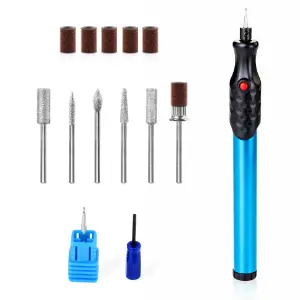
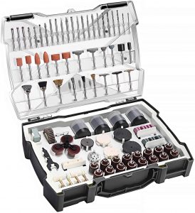
Easy to handle and use
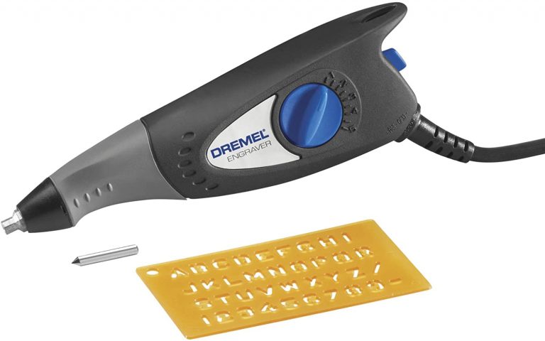
Customer service
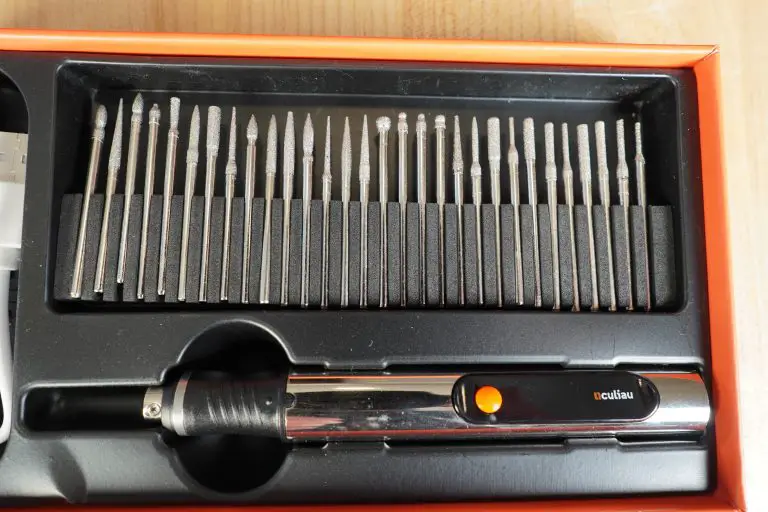
Plenty of included bits
Not the cheapest option

Lightweight
Easy to control
Included stencils
May be underpowered for some materials
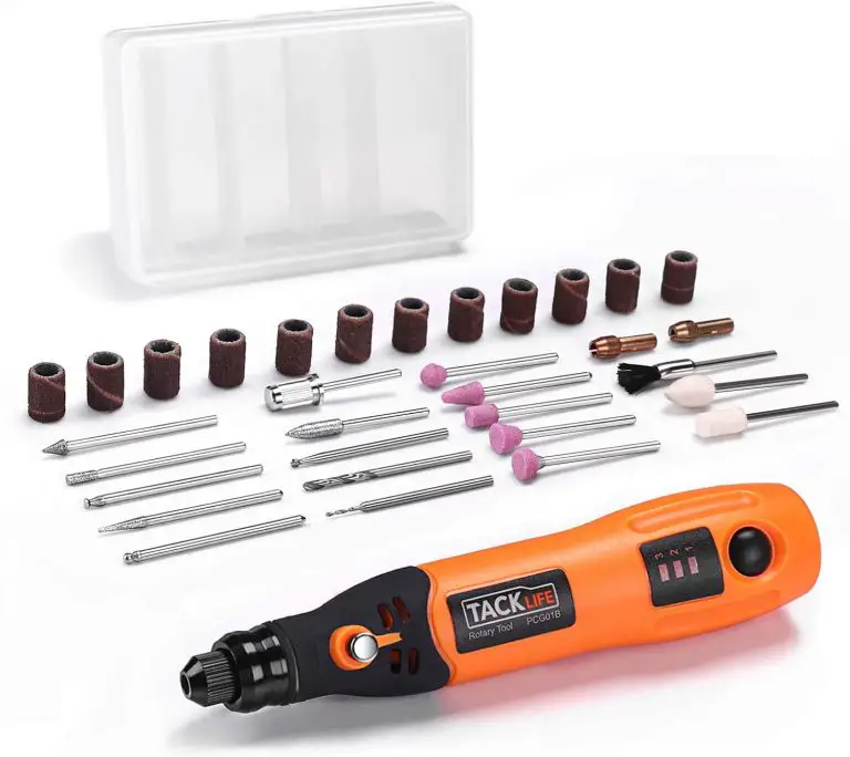
Adjustable depth setting
Warranty
Hard to install bit
Loud
Adjustable depth setting
Warranty
Hard to install bit
Loud
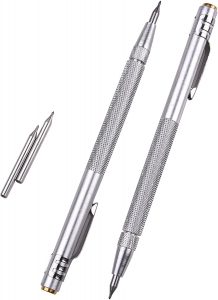
No power required
Doesn't engrave deep
Symbol Name | Symbol | Code |
Straightness | ▬ | ALT+22 |
Flatness | ▱ | 25B1 - ALT+X |
Circularity | ◯ | 25EF – ALT+X |
Cylindricity | ⌭ | 232D – ALT+X |
Profile of a Line | ∩ | ALT+239 |
Profile of a Surface | ⌓ | 2313 – ALT+X |
Angularity | ∠ | 2220 – ALT+X |
Perpendicularity | ⊥ | ALT+8869 |
Parallelism | // | 2225 – ALT+X |
True Position | ⌖ | 2316 – ALT+X |
Concentricity | ◎ | ALT + 10686 |
Symmetry | ⌯ | 232F – ALT+X |
Circular Runout |
| 2197 – ALT+X |
Total Runout | ⌰ | 2330 – ALT+X |
Free state | Ⓕ | ALT + 9403 |
Least material condition | Ⓛ | ALT + 9409 |
Maximum material condition |
| ALT + 9410 |
Projected tolerance zone | Ⓟ | ALT + 9413 |
Regardless of feature size (RFS) | Ⓢ | ALT + 9416 |
Tangent plane | Ⓣ | ALT + 9417 |
Unequally disposed tolerance | Ⓤ | ALT + 9418 |
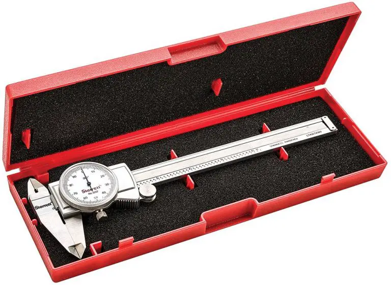
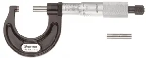
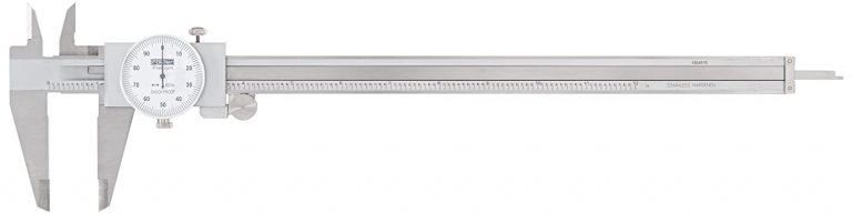
Exceptional accuracy
Built to last
None
Price point
Customer service
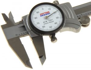
Not "shock proof"
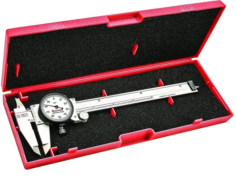
The usual Starrett quality
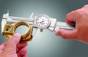
Accuracy
Hard to take smaller measurements
Cost
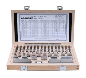
Cost
Reduced accuracy
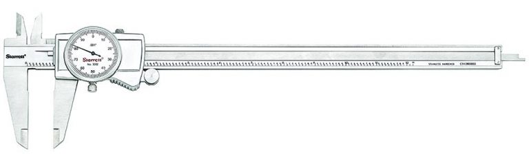
Excellent quality
Cost