Beginner’s Guide to Blueprint Reading

Learning to read blueprints can be hard. That’s why we’ve broken down the process into bite size chunks. All of the basic components of an engineering drawing are detailed below with links throughout to give you more info on each subject.

Use the table of contents below to jump straight to your topic of choice and if you don’t find what you are looking for please leave a comment at the bottom and we will tackle any blueprint related questions we may have missed.

Title block

title block example
Title block example

A blueprint title block contains the high-level identification information. The title block of a blueprint can vary quite a bit across different companies. In general, the title block can be found in the bottom right of the blueprint and will include the following:

  1. Drawing or part number and revision
  2. Part name
  3. Company name
  4. 1st or 3rd angle projection
  5. Scale

Tolerance block

tolerance block example
Tolerance block example

The tolerance block, sometimes referred to as the general tolerance block, is usually located in the bottom right or bottom middle section of the blueprint. The tolerance block identifies the tolerances associated with dimensions that are not directly listed on the drawing.

This can include items such as the blueprint dimensional units (imperial or metric) or surface roughness requirements.

Units of measurement

The units of the print are very important because there is a huge difference between 25.4mm and 25.4 inches. The measurement units will often be called out in the title block or tolerance block but occasionally will be in another section of the blueprint such as in the notes.

Angular units are important also but there is usually less confusion associated with them because decimal degrees and degrees, minutes, seconds are so different.

Types of projections

Projections are different ways of representing parts on a blueprint. Basically this means there are different methods of showing the same part.

1st angle projection, sometimes referred to as the European convention, is a method of displaying the various views of the part as if the part has been flipped to each side.

Notice how the car is flipped below in each view of a 1st angle projection blueprint.

1st angle projection car example
1st angle projection example - click to enlarge

3rd angle projection, the American convention, is a method of displaying the various views of the part as if the part is placed in a bowl and rolled in the bowl to the other views.

Notice how the car is flipped below in each view of a 3rd angle projection blueprint.

3rd angle projection example - click to enlarge

Projections can be hard to describe in words. Just remember that 1st angle projections are a flop method and 3rd angle projection is a roll method. 

Types of tolerances

There are multiple ways of tolerancing a dimension. Below are the ways of directly dimensioning a feature with standard tolerances. GD&T tolerances are a separate topic altogether.

Limit tolerances

limit tolerance example
Limit tolerance example

Limit tolerances list a range that the dimension must fall within. No calculation needed. Simply keep it between the numbers.

Unilateral tolerances

unilateral tolerance blueprint example
Unilateral tolerance example

Unilateral tolerances are given when the allowable variation is in a single direction such as the example below. In this example, the part cannot have a diameter that is over 6mm.

Bilateral tolerances

bilateral tolerance blueprint example
Bilateral tolerance example

Bilateral tolerances, often referred to as plus or minus tolerances, have a nominal size and a tolerance in the positive and negative directions. Often this tolerance will be equal in both directions, but it doesn’t have to be. Sometimes you will see bilateral tolerances that allow more variation in one direction.

Notes section

Notes on a blueprint can have a huge impact on the component requirements. The notes are often where surface treatment requirements such as heat treating, anodizing and other similar requirements are documented.

Literally anything can be listed in the notes section and the items listed can have a large bearing on the complexity of the part.

Pay attention to your notes section, there are often critically important features and characteristics relative to the part listed.

Symbols

A wide range of symbols are used to create engineering drawings. There are also specialty blueprint symbols associated with items such as welding or electronic components, but I will only be covering the standard blueprint symbols including those related to geometric dimensioning and tolerancing (GD&T).

Center lines

Center lines, such as the center of a thru hole are depicted on a drawing with long and short lines spaced alternately.

In the example below, the centerlines are shown as blue lines.

hidden and center line blueprint example
Center lines and hidden lines example

Hidden lines

To show features in a blueprint view that would not actually be visible, hidden lines are used. These hidden lines are show on a drawing as lines made of dashes.

In the example above, the hidden lines are shown as red lines

Diameters

Diameter Blueprint GD&T Symbol o with line through it
Diameter symbol

Diameters are round or cylindrical features. Features such as the outside diameter of a part and the size of a hole or counterbore are examples of diameters. They will be referenced using the diameter symbol shown below.

Countersinks

Countersink Blueprint GD&T Symbol two lines pointing down
Countersink symbol

Countersinks are a chamfer on a hole that allows a fastener such as a screw to sit flush or below the part surface. The blueprint symbol for a countersink is shown below.

countersink blueprint example
Countersink callout example

Counterbores

Counterbore Blueprint GD&T Symbol u shape
Counterbore symbol

A counterbore is a circular hole that is deep enough to allow the head of a fastener to be recessed. Counterbores will be shown on a blueprint with a diameter and depth symbol associated with them.

counterbore blueprint example
Counterbore callout example

Radii

Radius callout example

Radii show up on prints for many different reasons. The most common application of a radius is to specify the maximum radius allowed in the bottom of a slot or hole. They are frequently used as a form of edge relief similar to a chamfer. While these are the most common radius uses, radii can be dimensioned for all kinds of internal and external features.

When a radius smoothly blends into a surface, it will occasionally be called out as a full radius or full R. A full R callout does not change the way a radius is measured or add any additional requirements.

Holes

thru hole blueprint example
Hole callout example

Holes are about as simple as they come. They come in two varieties, thru holes and blind holes. When shown on a drawing they will usually be referenced by their size and location to the center of the hole.

Datums

Datum Blueprint GD&T Symbol a in a box with arrow
Datum symbol

Datums are reference points for measurements and are utilized in many GD&T callouts. You will find datums shown on a drawing to identify the feature as a datum or as part of a GD&T callout in a feature control frame.

GD&T Symbols

gd&t symbols
gd&t symbols

Basic dimensions

Basic Dimension Blueprint GD&T Symbol dimension in a box
Basic dimension example

Basic dimensions are the theoretically perfect size or location of a part feature. The variation from this “perfect” size or location will be used to measure another characteristic of the part such as true position or profile. Basic dimensions do not have a tolerance themselves and instead are controlled by another GD&T callout.

Reference dimensions

Reference Dimension Blueprint GD&T Symbol dimension in parentheses
Reference dimension example

Reference dimensions are just what they sound like. They are placed on a print for reference only. They have no requirements associated with them and no tolerances either. They generally get used in one of two ways, they will be used to highlight something that might not be immediately clear without the reference dimension listed or they will be used to show the approximate dimension in another unit system (metric vs imperial units).

Chamfers

chamfer callout blueprint example
Chamfer callout example

Chamfers are used to remove the sharp edges of a part. This provides safety for both the part and the person using the part. Chamfers are frequently specified in many different places. They can be listed directly on the part, in the notes section or in the general tolerance block.

When the chamfers are small, at times they will be listed as a break edge.

Spotfaces

spotface example on mechanical blueprint drawing
Spotface callout example

Spotfaces are a small counterbore that is machined so that a fastener can sit flat on the part. They are essentially just shallow counterbores and will be dimensioned as such.

Bolt hole circles

basic dimensions for a bolt hole circle
Bolt hole circle callout example

A bolt hole circle will be shown on a print using multiple dimensions. This will include the size of the individual holes, the angle between the center of the bolt hole circle and the individual holes along with the size of the bolt hole circle itself.

Knurling

knurling blueprint callout examples
Knurling callout examples

Knurling is a textured pattern on a part. It is added for visual appeal or added grip. Knurls will be called out by the pitch, diameter, and type of knurling.

Surface finish/surface roughness

Surface Finish Blueprint GD&T Symbol check mark
Surface finish/roughness symbol

The surface finish quality is specified with the use of a check mark on the surface. The number above the start of the check is the required surface finish. If there are two numbers present, the surface roughness must fall within the range specified. If only one number is specified, the surface roughness must be less than or equal to the specified value.

Surface finish requirements are frequently specified directly on the applicable surfaces as well as in the notes section and general tolerance block.

Threads

Threads will be specified in either the ISO metric format or Unified National Coarse (UNC) thread format. This article clarifies the details of thread callouts.

Want to learn more?

GD&T is a complicated subject and understanding it correctly can be the difference between a perfect part and scrap.

The best way to learn GD&T is from experienced teachers who can break down the material into manageable pieces.

Luckily, we know someone.

And MachinistGuides.com readers get an exclusive discount on training!

Related articles

6 thoughts on “Beginner’s Guide to Blueprint Reading”

  1. Thank you for this!
    I need advice on the best book for learning how to read machinists blueprints.

    I have some experience with cad drawings, but started a new job, and the prints are small and very busy with lots of dims and lines. And, unfortunately , I am not allowed to take copies home,

    Any help would be greatly appreciated. Thank you.

    Reply
    • William,
      I am so glad this post helped.

      With regards to best books for learning to read blueprints, please see my post of the Best CNC and Machining Books. There are two blueprint reading books which I recommend. There is a Pocket Guide to GD&T which is a good starter book. It is lighter on content but also quite a bit cheaper than my other recommendation which is GD&T: Application and Interpretation. This book is extremely comprehensive and provides some really good guidance when it comes to reading blueprints. It includes a lot of pictures to help visualize some of the more complicated topics.

      I think the choice comes down to how deep you want to go into the subject. A pocket guide type reference will get you started but if you are going to make a career out of it, then a book that goes deeper on the subject will really be worthwhile.

      Good luck with the new job!

      Brandon

      Reply
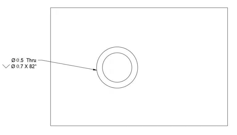
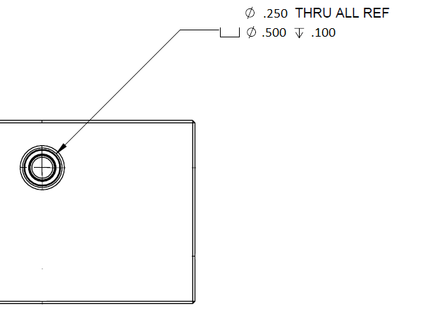
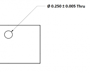
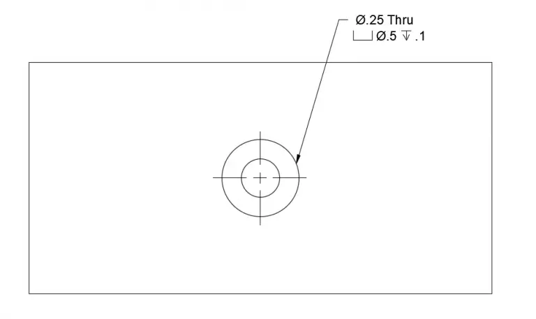
  2. This may be a nitpick but the Spotface hole example should have center lines and the Arrowhead and Leader line from the note should point at the hole center to be accurate. Beginners should know and understand details like this so they exhabit good practices and don’t have to break bad habits.
    Thank you for the consideration

    Reply
    • Allen,
      The devil is in the details! I appreciate you pointing this out.
      In the interest of simplifying things for those just starting out, I removed too much info.
      I agree that the centerline should be added and I have updated the example.
      Regarding the arrowhead and leader line, Figure 6-16 in ASME Y14.5-2018 shows that the arrowhead and leader line can point to the edge of the hole so I have left that as originally shown.
      Thanks for helping make this post as accurate as possible!
      Cheers,
      Brandon

      Reply

Leave a Comment