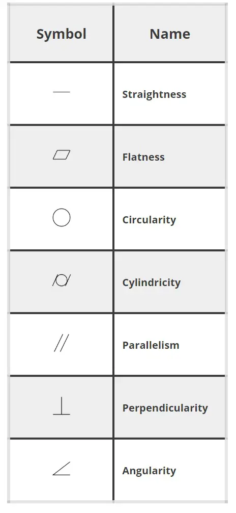
Symbol Name | Symbol | Code |
Straightness | ▬ | ALT+22 |
Flatness | ▱ | 25B1 - ALT+X |
Circularity | ◯ | 25EF – ALT+X |
Cylindricity | ⌭ | 232D – ALT+X |
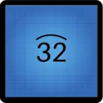
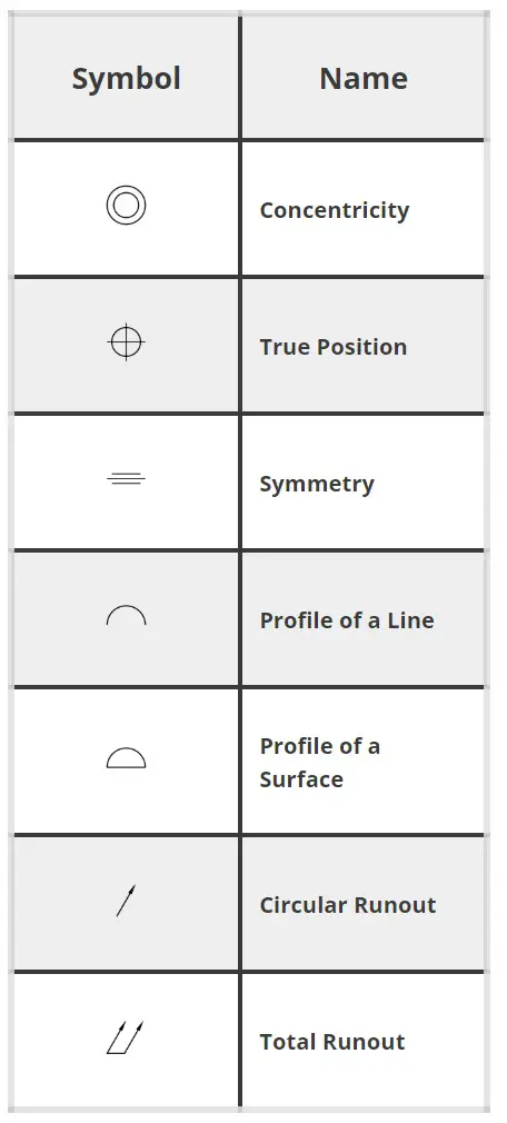
Profile of a Line | ∩ | ALT+239 |
Profile of a Surface | ⌓ | 2313 – ALT+X |
Angularity | ∠ | 2220 – ALT+X |
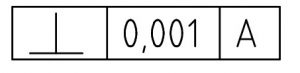
Perpendicularity | ⊥ | ALT+8869 |
Parallelism | // | 2225 – ALT+X |
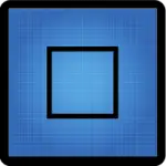
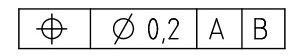
True Position | ⌖ | 2316 – ALT+X |
Concentricity | ◎ | ALT + 10686 |
Symmetry | ⌯ | 232F – ALT+X |
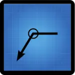
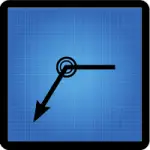
Circular Runout |
| 2197 – ALT+X |
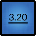
Total Runout | ⌰ | 2330 – ALT+X |
Free state | Ⓕ | ALT + 9403 |
Least material condition | Ⓛ | ALT + 9409 |
Maximum material condition |
| ALT + 9410 |
Projected tolerance zone | Ⓟ | ALT + 9413 |
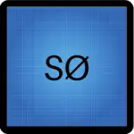
Regardless of feature size (RFS) | Ⓢ | ALT + 9416 |
Tangent plane | Ⓣ | ALT + 9417 |
Unequally disposed tolerance | Ⓤ | ALT + 9418 |
Blueprint Reading Guides


Beginner’s Guide to Blueprint Reading


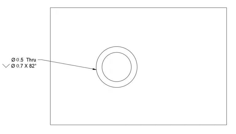
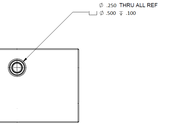
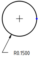
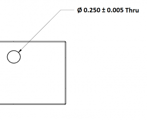
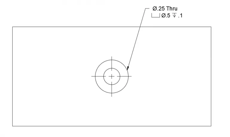


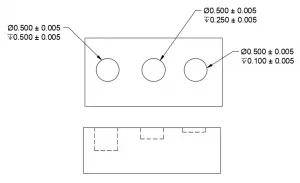
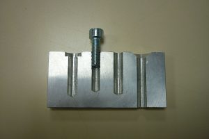
Guide to Holes on Blueprints [Types, Symbols & Features]