How to insert symbols into a Microsoft Word document
To insert GD&T symbols into Word, take note of the codes in the table below.
There are two types of symbols below.
Some are alt codes (ALT+248) and some are Unicode characters (25B1 then ALT+X).
Alt codes are entered by holding the ALT key and pressing the number code. Unicode characters are entered by typing the code and then holding the ALT key and pressing X.
How to insert GD&T symbols into a Microsoft Excel document
Not all the codes listed below will work in Excel.
The ALT codes (ALT+248 style) work but the Unicode characters (25B1 then ALT+X style) do not.
The best way to insert the GD&T symbols into Excel is to copy and paste the symbols.
GD&T Symbols Alt Codes
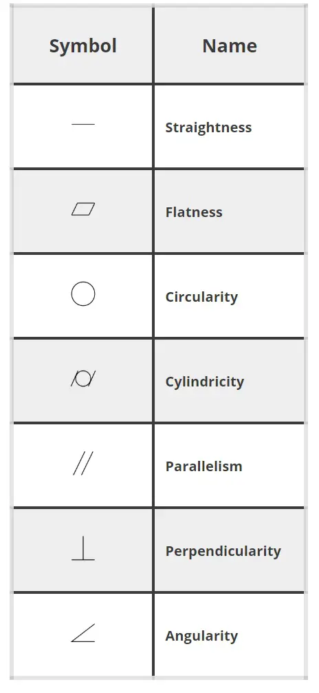
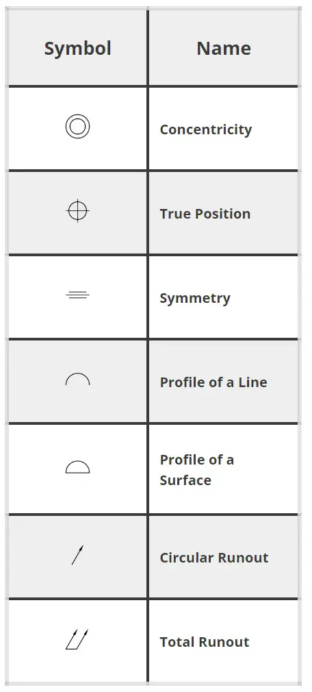
Symbol Name | Symbol | Code |
Straightness | ▬ | ALT+22 |
Flatness | ▱ | 25B1 - ALT+X |
Circularity | ◯ | 25EF – ALT+X |
Cylindricity | ⌭ | 232D – ALT+X |
Profile of a Line | ∩ | ALT+239 |
Profile of a Surface | ⌓ | 2313 – ALT+X |
Angularity | ∠ | 2220 – ALT+X |
Perpendicularity | ⊥ | ALT+8869 |
Parallelism | // | 2225 – ALT+X |
True Position | ⌖ | 2316 – ALT+X |
Concentricity | ◎ | ALT + 10686 |
Symmetry | ⌯ | 232F – ALT+X |
Circular Runout |
| 2197 – ALT+X |
Total Runout | ⌰ | 2330 – ALT+X |
Free state | Ⓕ | ALT + 9403 |
Least material condition | Ⓛ | ALT + 9409 |
Maximum material condition |
| ALT + 9410 |
Projected tolerance zone | Ⓟ | ALT + 9413 |
Regardless of feature size (RFS) | Ⓢ | ALT + 9416 |
Tangent plane | Ⓣ | ALT + 9417 |
Unequally disposed tolerance | Ⓤ | ALT + 9418 |


Common Blueprint Symbol Alt Codes
Symbol Name | Symbol | Code |
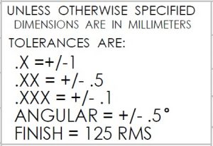
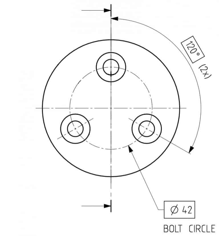
Degree | ° | ALT + 248 |
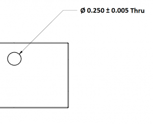
Plus or Minus | ± | ALT+241 |
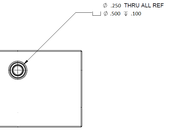
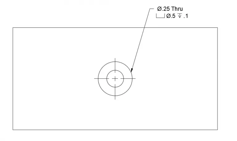
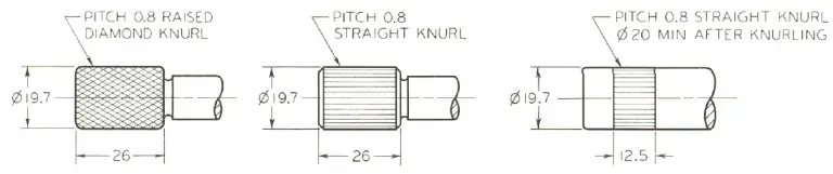
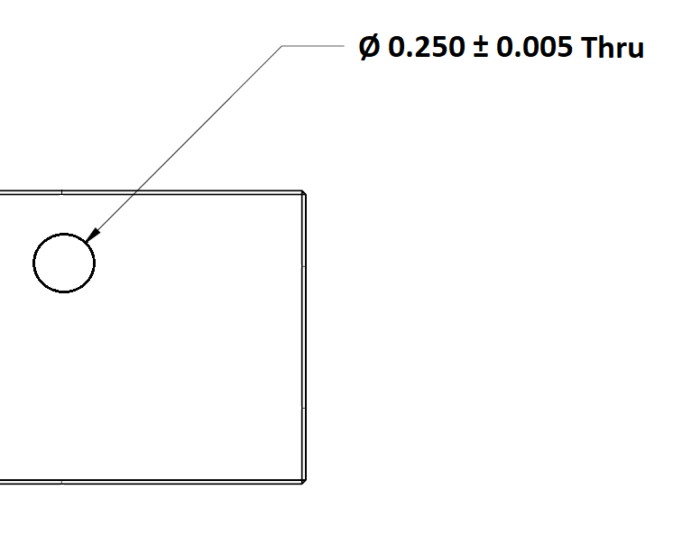
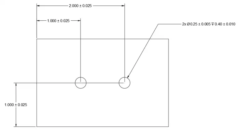
Diameter | Ø | ALT+0216 |
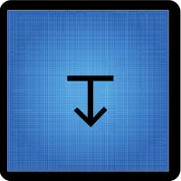
Depth | ↧ | ALT + 8615 |
Greater Than or Equal To | ≥ | ALT+242 |
Less Than or Equal To | ≤ | ALT+243 |
Counterbore | ⌴ | ALT+9012 |
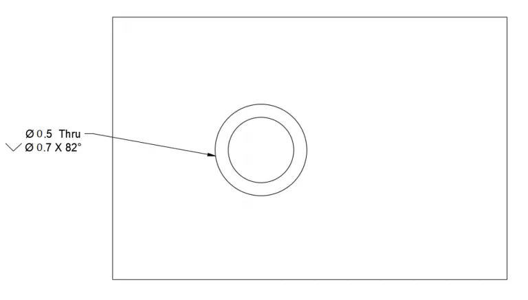
Countersink | ⌵ | ALT+9013 |
Micro | µ | ALT+230 |
Surface Finish | ✓ | 2713 - ALT+X |
Centerline | ℄ | ALT + 8452 |