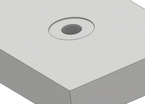


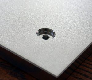
A full radius is a radius that smoothly blends into another surface. Full radius is most often specified in a rounded slot feature or a feature that mimics a rounded slot.
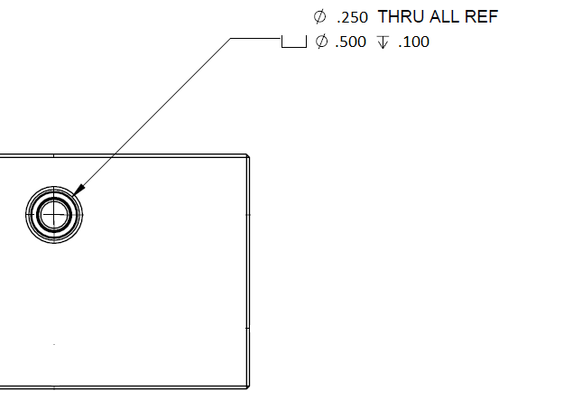
A full radius sometimes noted as a true radius or full R is outdated language and not part of the current revision of the drawing standard ASME Y14.5. The full radius callout is referencing a smooth transition from the radius to an adjacent surface.
Because no reference standard documents the requirements of a full radius, there are no specific requirements for the callout.
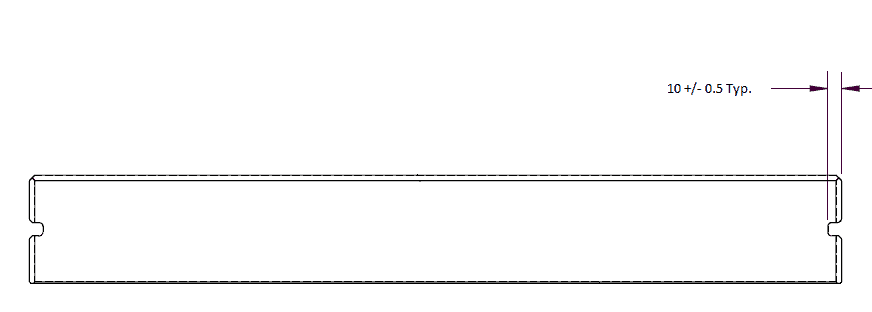
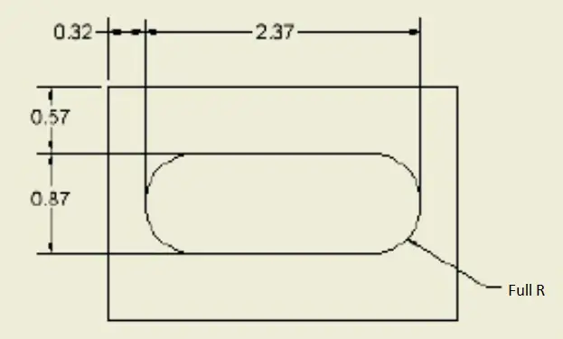
When a full radius, true radius or full R is called out on the drawing, the blueprint drafter is attempting to control the blend into and out of the specified radius.
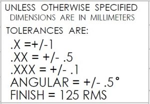
There is no difference between the drawing callouts of full radius, true radius and radius. Because there are no specific requirements for a full radius referenced by any drawing or GD&T standards, there is no difference in the requirements of a full radius or full R vs a radius or R. A full radius does not have a tolerance. A radius if drawn correctly will have some form of a +/- tolerance or be controlled through a GD&T requirement such as profile or cylindricity.
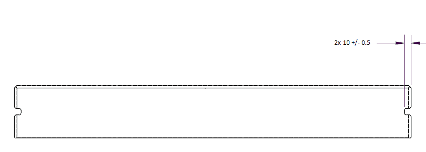
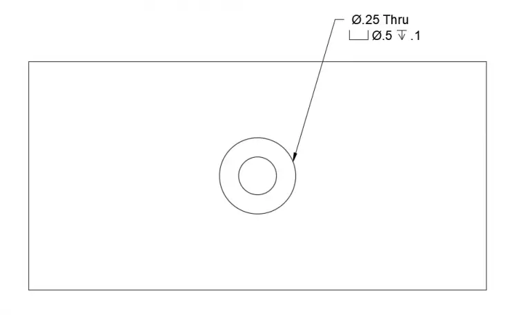
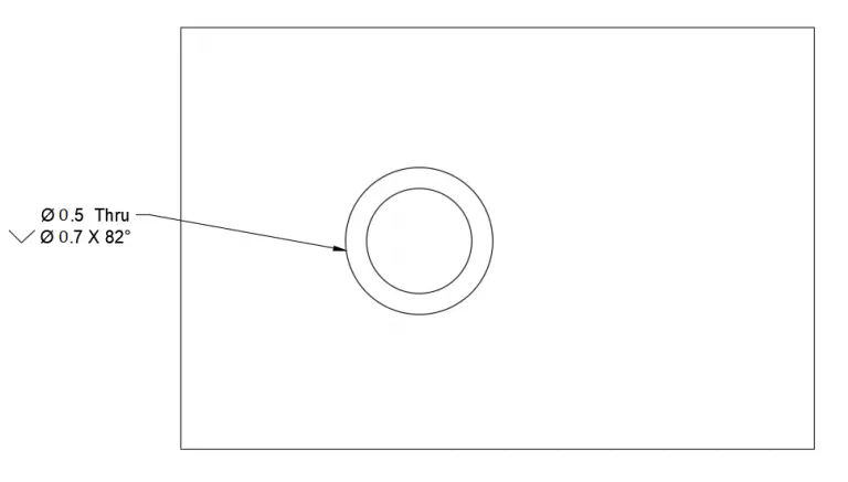
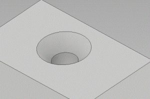
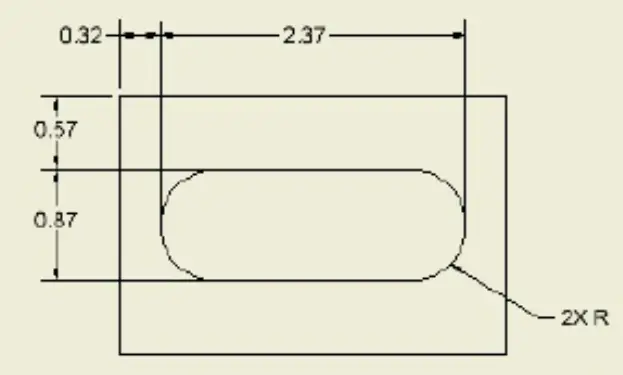
There is no difference between the requirements of the example below or the previous one.
GD&T is a complicated subject and understanding it correctly can be the difference between a perfect part and scrap.
The best way to learn GD&T is from experienced teachers who can break down the material into manageable pieces.
Luckily, we know someone.
And MachinistGuides.com readers get an exclusive discount on training!
Get the Best GD&T Training AvailableFor more information see these related articles:


A cheat sheet type reference for the most common GD&T symbols.
See also our GD&T Font – GD&T Keyboard Shortcuts List
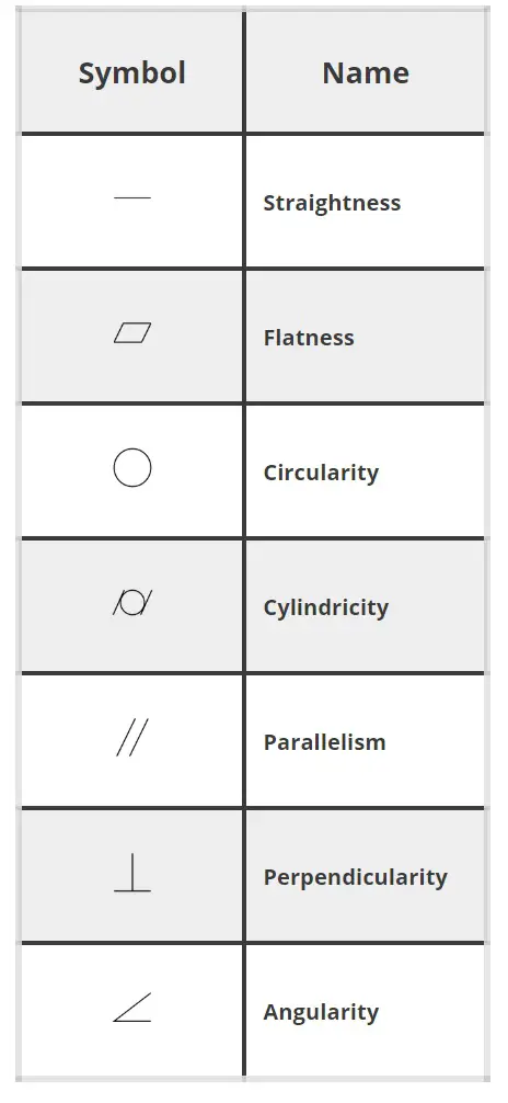
Symbol | Name | Description |
 | Straightness | Straightness is how close to a straight line a feature is. |
 | Flatness | Flatness is how flat a feature is. All points on the feature must lie within two parallel planes that are spaced the tolerance width apart. |
 | Circularity | Often called roundness. Circularity refers to how close to a perfect circle a single location is. Circularity is at one location. This can be thought of as a single circle on a cylinder. Usually circularity would be checked at multiple locations along the cylinder. This cylinder can be the inside of a hole, the outside of a shaft or various other features. |
 | Cylindricity | Cylindricity is the same as circularity (often called roundness) with the exception that the requirement applies across the whole surface instead of at a single location. Cylindricity works to control taper whereas circularity does not. |
 | Parallelism | Parallelism refers to how close to 180 degrees two surfaces are. |
 | Perpendicularity | Perpendicularity is how close to 90 degrees two features are. This can be any combination of planes or axes. |
 | Angularity | Angularity is the same as perpendicularity with the exception that the two features are not at 90 degrees to one another but instead at a different specified angle. |
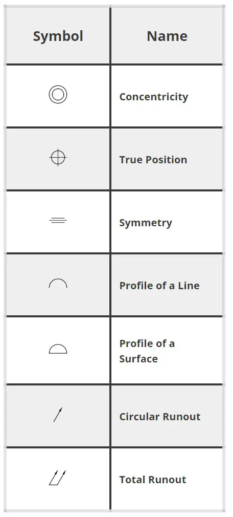
 | Concentricity | Concentricity is how close the axes of two features run together. |
 | True Position | True position is a theoretically exact location of a feature. |
 | Symmetry | Symmetry is the same as concentricity but is applied to features that aren’t round. This means that the axes or centers of two features must run together. |
 | Profile of a Line | Profile of a line controls the shape of a cross section of a feature. It can control size, form and location. |
 | Profile of a Surface | Profile of a surface is similar to the profile of a line tolerance but it controls the entire surface instead of a single cross section. |
 | Circular Runout | Circular runout controls the runout in a single location of a circular feature such as a cylinder. |
 | Total Runout | Total runout controls the runout of an entire surface of a circular feature instead of at a single location. When compared to circular runout, total runout would check the entire cylinder. |
GD&T is a complicated subject and understanding it correctly can be the difference between a perfect part and scrap.
The best way to learn GD&T is from experienced teachers who can break down the material into manageable pieces.
Luckily, we know someone.
And MachinistGuides.com readers get an exclusive discount on training!
Get the Best GD&T Training AvailableFor more information see these related articles:
Symbol | Name | Description |
| | Straightness | Straightness is how close to a straight line a feature is. |
| | Flatness | Flatness is how flat a feature is. All points on the feature must lie within two parallel planes that are spaced the tolerance width apart. |
| | Circularity | Often called roundness. Circularity refers to how close to a perfect circle a single location is. Circularity is at one location. This can be thought of as a single circle on a cylinder. Usually circularity would be checked at multiple locations along the cylinder. This cylinder can be the inside of a hole, the outside of a shaft or various other features. |
| | Cylindricity | Cylindricity is the same as circularity (often called roundness) with the exception that the requirement applies across the whole surface instead of at a single location. Cylindricity works to control taper whereas circularity does not. |
| | Parallelism | Parallelism refers to how close to 180 degrees two surfaces are. |
| | Perpendicularity | Perpendicularity is how close to 90 degrees two features are. This can be any combination of planes or axes. |
| | Angularity | Angularity is the same as perpendicularity with the exception that the two features are not at 90 degrees to one another but instead at a different specified angle. |
| | Concentricity | Concentricity is how close the axes of two features run together. |
| | True Position | True position is a theoretically exact location of a feature. |
| | Symmetry | Symmetry is the same as concentricity but is applied to features that aren’t round. This means that the axes or centers of two features must run together. |
| | Profile of a Line | Profile of a line controls the shape of a cross section of a feature. It can control size, form and location. |
| | Profile of a Surface | Profile of a surface is similar to the profile of a line tolerance but it controls the entire surface instead of a single cross section. |
| | Circular Runout | Circular runout controls the runout in a single location of a circular feature such as a cylinder. |
| | Total Runout | Total runout controls the runout of an entire surface of a circular feature instead of at a single location. When compared to circular runout, total runout would check the entire cylinder. |