Table of Contents
ToggleWhat is a datum?
How are datums used?
Symbol for a datum

Datum names
How is a datum used in a feature control frame?
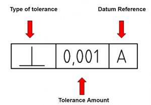
Datums are placed at the end of a feature control frame.
Primary datums
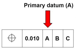
A primary datum is the main locating surface used for alignment.
Think of a box set on a table. In this case the bottom of the box is the primary datum.
The table would be used to simulate the primary datum. In this example measurements could be taken from the table to other features of the box to verify they meet the required dimensions.
The primary datum controls one axis of freedom. The box can move back and forth or spin in place on the table but it can not turn end over end. This is similar to the way a granite surface plate is used in machine shops all over the world.
Secondary datums
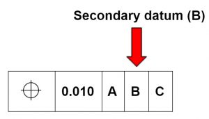
A secondary datum is the secondary alignment feature. In the box on a table example, if the table and the box were pushed up against a wall then the wall would be the secondary datum.
The box would contact the wall at a minimum of two points. Contacting the wall would constrain the movement in another axis.
The table controls end over end movement. The wall stops the box from spinning. It is however still able to move back and forth along the wall.
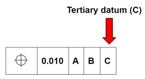
Tertiary datums
What is a datum target?
A datum target is a specified location that is used to measure a part. It identifies the point(s) from which measurements will be taken.
The use of datum targets or points provides a level of control over the datum surface. Some surfaces are incapable of being used like a normal datum.
A very large datum surface or a surface that has a lot of variation in its form are two common reasons why datum targets are used.
Datum targets are also used to mimic real world use such as contact points in an assembly.
Datum target symbol
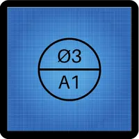
The top half of the datum target symbol is often empty. The upper half lists the area of the datum target when specified. The lower half of the datum target symbol lists the datum target name.
Is a datum real or theoretical?
Both really. The real datum is the actual surface referenced. This surface is imperfect and will have variation to it.
No surface is perfectly true.
In practice though a datum is used as a theoretically perfect surface.
A good example would be placing a datum surface down on a surface plate which is known to be very flat. The imperfect actual surface of the part will come to rest on the high points sitting on the surface plate. Measurements can be taken from the surface plate as if it was the datum surface itself.
Examples

True position callout referencing datums A & B

Perpendicularity callout referencing datum A

Circular runout referencing datum A
Datum dimensioning vs chain dimensioning
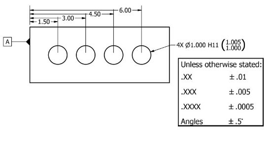
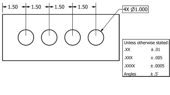
Chain dimensioning is the process of dimensioning features of one another in a row. Datum dimensioning is used when features are referenced from a common point. Take a look at the differences in the examples below.
A disadvantage of chain dimensioning is that the tolerances stack up. This means that the location of the far right hole can actually vary by as much as +/- 0.040”.
The example which uses datum dimensioning maintains the +/- 0.010” tolerance for each location. Chain dimensioning can be a perfectly acceptable way to tolerance your parts, just make sure you have taken into account the additional tolerance that can apply to the feature.
Plural of datum
Want to learn more?
GD&T is a complicated subject and understanding it correctly can be the difference between a perfect part and scrap.
The best way to learn GD&T is from experienced teachers who can break down the material into manageable pieces.
Luckily, we know someone.
And MachinistGuides.com readers get an exclusive discount on training!
Related Articles
For more information see these related articles:
