Overview
Being a CNC operator is easily the simplest of all CNC jobs. A CNC operator is typically an entry level position and they are tasked with keeping the machines running and constantly making parts.

In most cases, someone else will program and setup the machine while an operator is asked to keep it between the lines. This often means checking parts in some fashion as they come off the machine and occasionally making small adjustments to keep everything within the allowable tolerances.
CNC operators are often referred to as button pushers. Quite honestly, operating a CNC isn’t the most highly skilled position. As a result, the pay isn’t that high, but most will find it still beats working retail and isn’t nearly as backbreaking as something you might find in one of the construction trades.
So, let’s jump right in to some of the most frequently asked questions about becoming a CNC operator.
What does a CNC operator do?
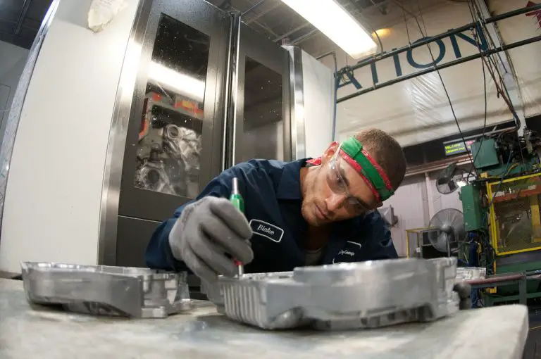
A CNC operator pushes buttons to keep the CNC machines running while performing basic inspection of the machined parts.
As an entry-level position, all of the skills necessary for a CNC operator to possess would be taught to a new employee. Any experience or knowledge that an applicant bring with them would be icing on the cake.
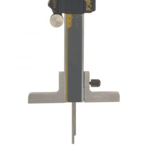
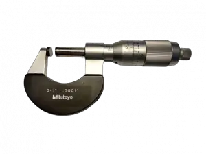
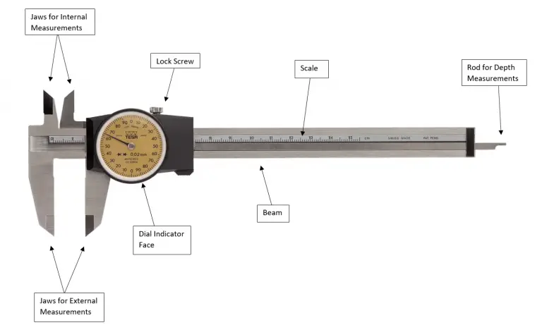
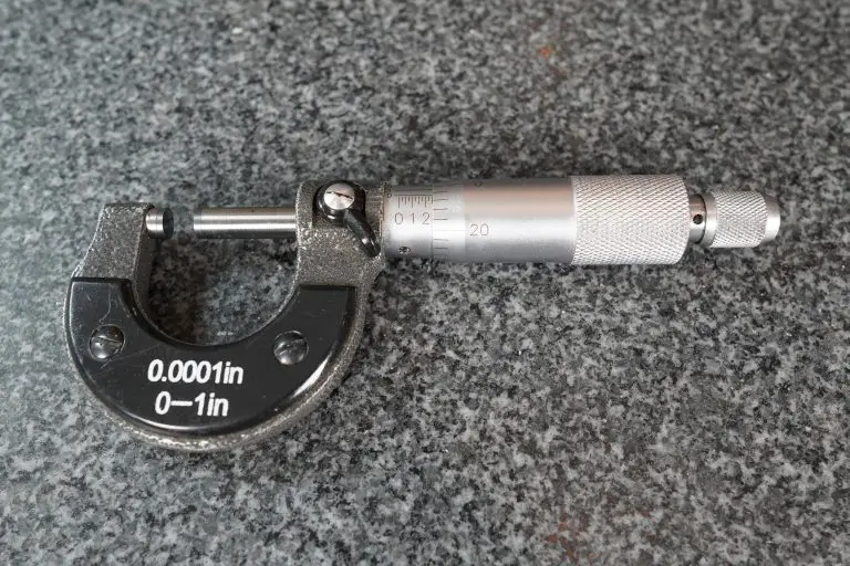
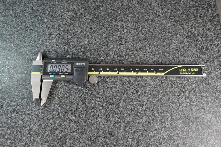
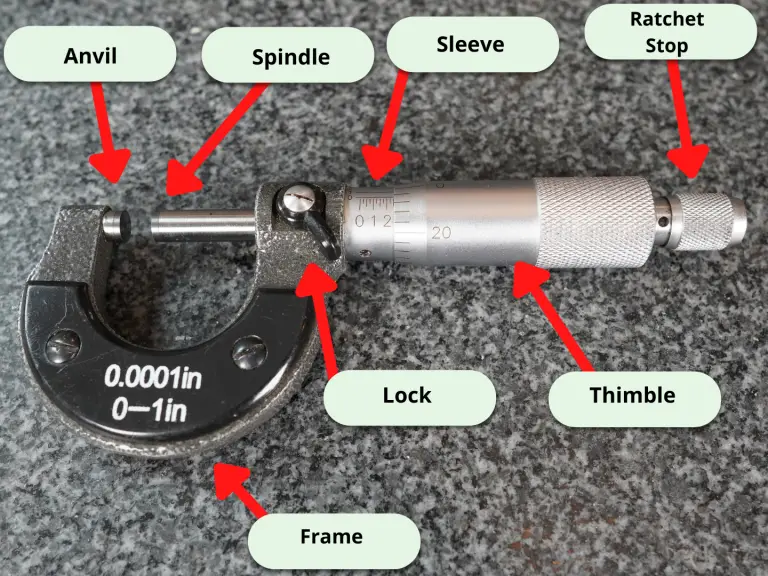
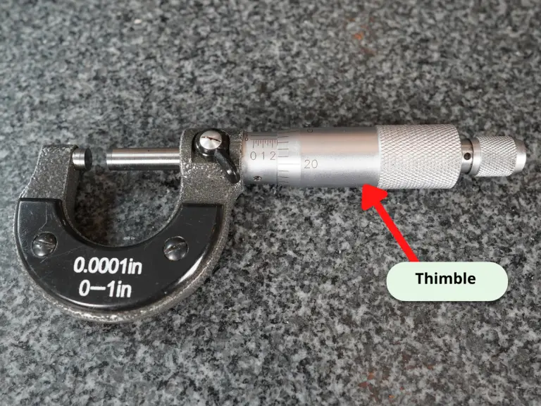
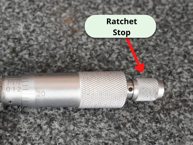
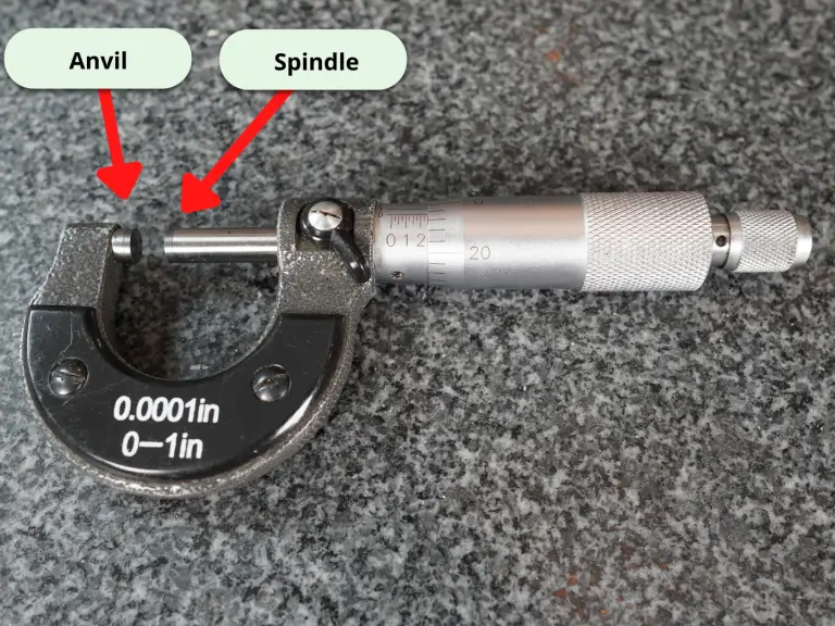
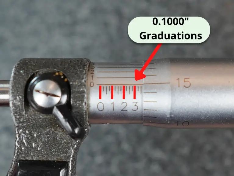
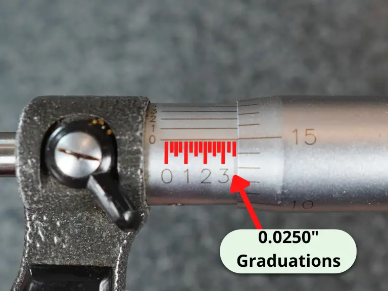
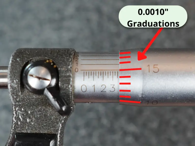
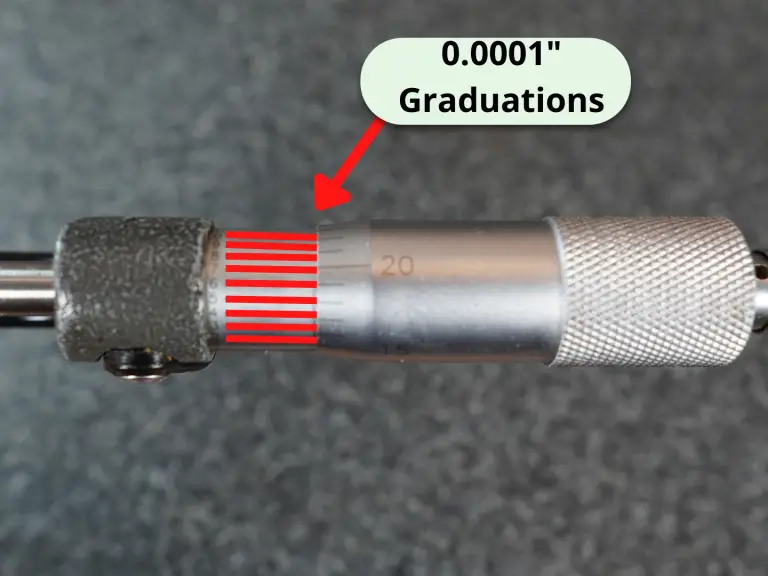
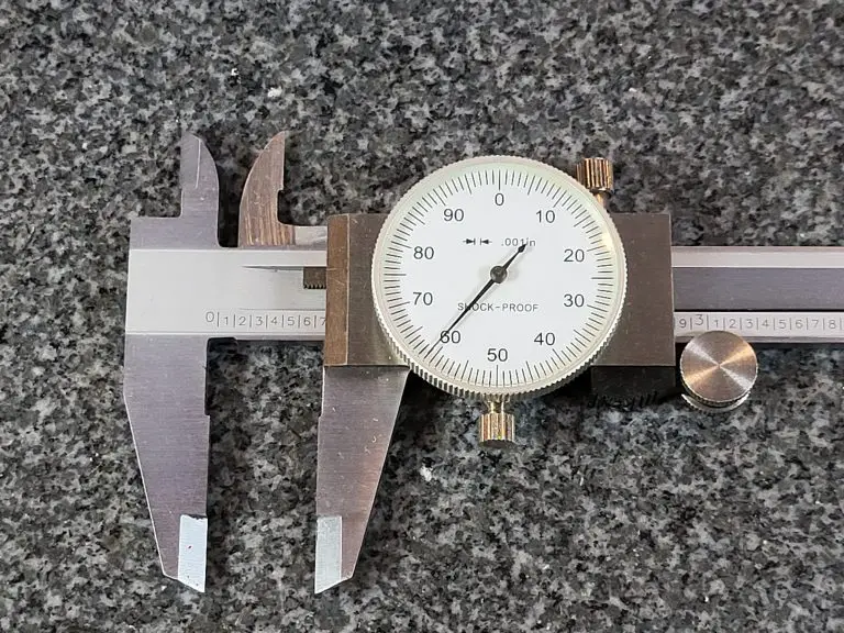
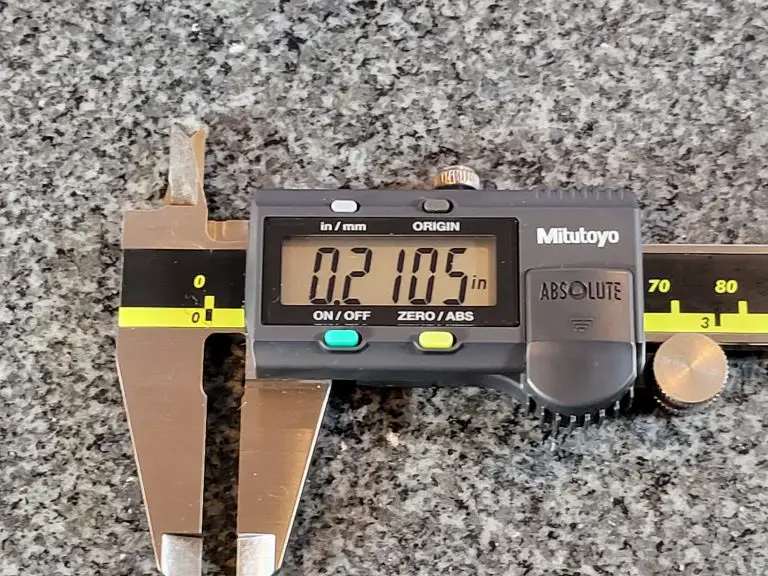
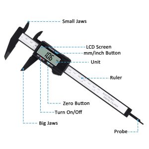
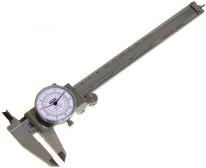
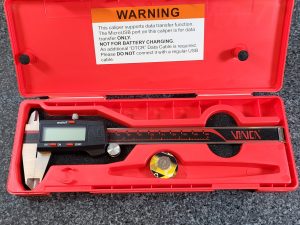
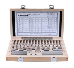
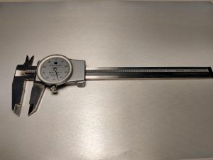
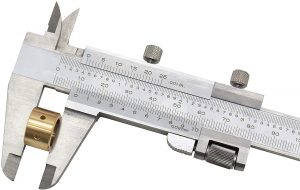
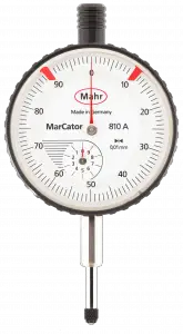
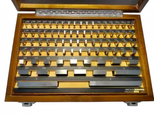
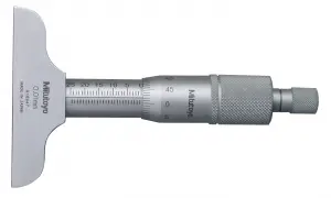
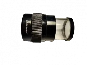
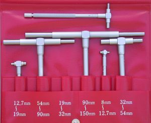
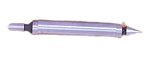
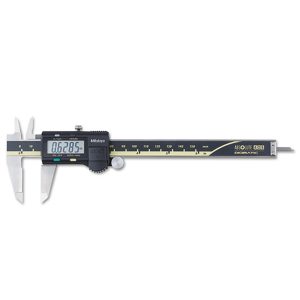
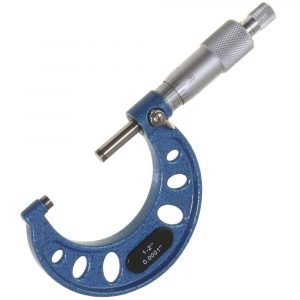
Operators will be expected to do simple math such as adding and subtracting. Additionally, they will use measuring gauges such as micrometers, calipers, a pocket comparator and often dial indicators.
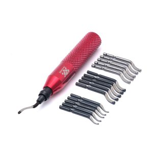
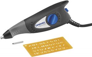
Basic hand tools including screwdrivers, mallets and deburring tools will get everyday use as well. The real benefit of being a CNC operator is that it can be a great stepping stone to an extremely in demand profession once you have expanded your skillset and advanced to the level of CNC setup and/or programming.
Experience with blueprints, trigonometry or handheld measuring equipment such as micrometers and calipers would be very sought after for any company.
Typical CNC operator job description
MachinistGuides.com is seeking a quality-oriented CNC Machine Operator to join our dynamic team.
The CNC Machine Operator will work with other team members and report to the Shop Manager. This role is responsible for reading blueprints, checking finished parts, and operating CNC mills and/or lathes.
The CNC Machine Operator will:
- Safely operate a CNC machine to create precision components
- Read and interpret blueprints, diagrams, sketches, and verbal instruction
- Maintain pace of production to meet scheduled demands
- Safely load and unload CNC production equipment
- Have the ability to lift 50+lbs and stand for several hours
Desired Skills:
- CNC machine operator/manufacturing experience
- Thorough knowledge of standard manufacturing concepts, practices, and procedures
- Have a strong work ethic and a positive attitude
- Attentive to detail and instruction
Compensation commensurate with experience. A list of benefits which may include paid time off, 401k, medical, dental, life insurance, and/or holidays.
CNC operator skills
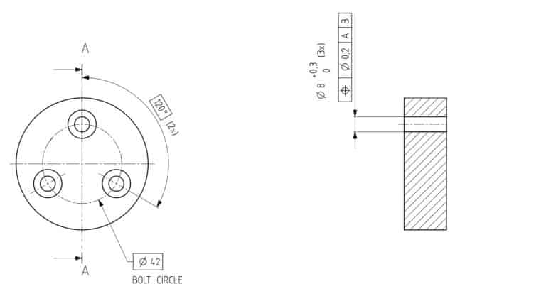
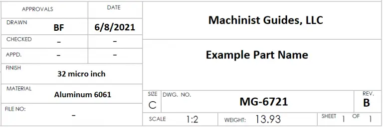
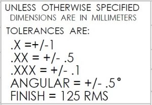
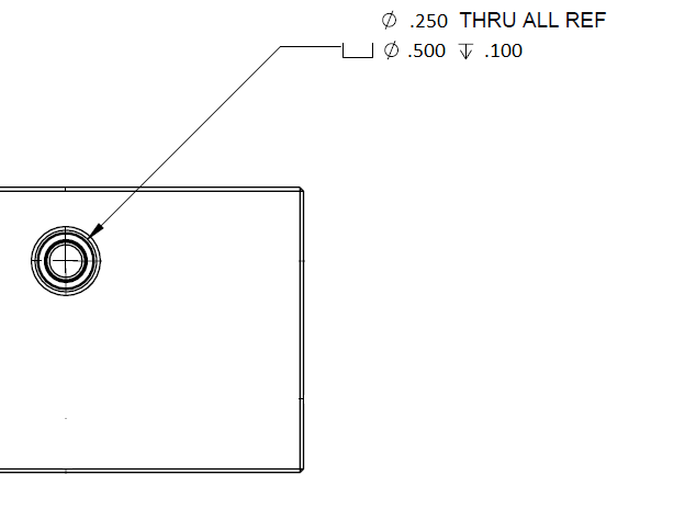
- Blueprint reading
- Simple math including addition and subtraction of decimals
- Hand tools
- Handheld measuring equipment use
- Some light trigonometry
Check out our Beginner’s Guide to Blueprint Reading to gain a leg up on the competition.
Our guide to machinist lingo will help you talk the talk at your new job as well.
How much does a CNC operator make?

According to GlassDoor.com, the average pay for a CNC operator is $38,490 per year. With a typical 40-hour week that comes out to $18.50 an hour.
Keep in mind that pay will vary by region, but this should give you a good idea of where you will start. The nice thing about CNC and machining work is that there is often quite a bit of room for growth.
For reference, CNC programmers can often make $30+ an hour.
How long does it take to become a CNC operator?
Being a CNC operator is an entry level position and as a result, you can be a CNC operator on your first day on the job.
You might not the most productive employee on day one, but you will be tackling the normal everyday responsibilities of more experienced operators.
Is it difficult to learn how to be a CNC operator?
CNC operation is not a difficult job to learn. As an entry level position, the skills needed to be a great CNC operator can be learned in a pretty short amount of time.
Is being a CNC operator stressful?
Generally speaking, CNC operation is not a stressful job. Of course this will vary from company to company but because the position is entry level, there is very little responsibility on the operators part.
It will be possible to find some businesses that work with a very heavy “produce, produce, produce” mentality and in these cases, the job can get more stressful. This is more of a product of the management style than the actual position itself so make sure to do some research online to check out some reviews for any potential employers.
Is being a CNC operator boring?
This is a very subjective question, but I believe many would find the position boring. A CNC operator job will usually be fairly repetitive while not being overly difficult mentally or physically.
The good news is that if your are looking for something to keep things a little more interesting then there will often be opportunities for advancement if you are willing to learn and put in a little effort.
You should also know that boring is also a term for precision machining of a hole by a machine such as a CNC mill or lathe.
Do you need a degree to be a CNC operator?

Being a CNC operator does not require a college degree in any form. Local community colleges often offer certificate programs or crash course type coursework that will be looked upon very favorably for any new hire.
Many companies however will require a high school degree or equivalent. Larger companies are usually the ones who have this requirement. Smaller shops are generally more lenient.
What kinds of certifications and training are available to become a CNC operator?
Training, courses, classes, and certifications are available at colleges across the country with many community colleges leading the way.
Check out your local community college’s website to see if they offer training that may be beneficial. You will likely be surprised at the number of different options they offer.
Another valuable resource is your states manufacturing extension program. These organizations are usually aimed more at helping businesses with workforce development, but they often offer subsidized training that can give you a huge leg up in the job market.
YouTube is a great resource as well and there are thousands of high-quality videos out there to teach you all about every aspect of CNC work.
If you want a more structured approach, then check out our post on the best CNC and machining books. Many of these books are the same reference material that the college classes mentioned above will use.
What should you put on a resume to get a position as a CNC operator?
To get a job as a CNC operator make sure to mention any of the following items that may apply:
- Math skills, especially anything related to trigonometry
- Blueprint reading experience of any kind
- Mention your attention to detail
- Describe how reliable and dependable you are
Tips for finding a good position as a CNC operator
Research, research, research.
Actually it’s not that hard. A single research is probably enough. It is actually pretty easy to find a good job as a CNC operator.
Look for company reviews on sites such as Indeed or GlassDoor. Take it all with a grain of salt but in my experience, any company who has more than a few reviews will be pretty easy to determine the overall “vibe” of the business.
Look for a company that stresses quality over quantity and you will be headed in the right direction.
Related articles
For more information check out these related articles: