


Basic dimensions are shown on a blueprint enclosed in a box. But what do they mean?
Keep reading to find out.
A basic dimension is a theoretically exact size or location.
Basic dimensions do not have a tolerance applied to them, this includes any general tolerance blocks.
Instead a separate is listed on the drawing that uses the basic dimension.
An example of this would be a true position callout for a hole or set of holes. The basic dimension(s) specify the location of the hole.
The true position of the hole is calculated based on the difference of the actual location compared to the basic dimensions theoretically exact location.
Basic dimensions are used for calculations. They are used to calculate various geometric dimensioning and tolerancing (GD&T) characteristics such as true position, profile or angularity.
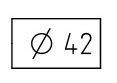
In the example above, the 120 degree callout and the 42 diameter bolt circle are the basic dimensions and the true position of 0.2 is the characteristic controlling the basic dimensions.
The symbol for a basic dimension is the dimension shown enclosed in a rectangular frame or box.
This is the convention identified in the blueprint drawing standard ASME Y14.5.
Some drawings may list a basic dimension not in a rectangular frame but instead the dimension will be followed by a Bsc. notation. This is more common on older drawings and does not change the way basic dimensions are used.
A basic dimension itself does not have a tolerance. General tolerance blocks do not apply to a basic dimension.
Instead its value is used to compute another characteristic such as angularity, profile or true position.
Basic dimensions are associated with another tolerance or dimension. While they don’t have a tolerance tied to themselves, they are used to calculate another toleranced feature such as the true position of a hole.
Reference dimensions are simply placed on a drawing or blueprint for reference. They have no tolerance associated with them. No matter how far off the given value a reference dimension is, it would never be cause for rejection.
A basic dimension being far off its nominal value would not be cause for rejection itself, but its effect on another feature referencing the basic dimension could be cause for rejection. So if a basic dimension was far off the nominal location, another tolerance would likely be out of spec.
Regular dimensions have a tolerance assigned to them. This can be directly assigned to the individual dimension or it can be the general tolerances. The regular dimension must fall within the limits of the tolerance.
A basic dimension is instead controlled by another characteristic. The basic dimension can vary by any amount but it must not deviate from the nominal value to the point that the other characteristic (true position callout, profile callout, etc.) is no longer within the specified limits.
While there isn’t a strict requirement anywhere to include them, I would recommend reporting their values on an inspection report.
The features have been measured and you likely already have the values. By recording them, you will provide more information and value for your customer.
You must report the feature control values such as true position, profile value, etc. that use the basic dimension to be calculated.
The requirement for reporting basic dimensions is the same for first article inspection reports. Be aware that some customers may require them even though there is no requirement per AS9102.
GD&T is a complicated subject and understanding it correctly can be the difference between a perfect part and scrap.
The best way to learn GD&T is from experienced teachers who can break down the material into manageable pieces.
Luckily, we know someone.
And MachinistGuides.com readers get an exclusive discount on training!
For more information see these related articles:
© 2024 Machinist Guides
