Guide to Becoming a CNC Operator

Overview

Being a CNC operator is easily the simplest of all CNC jobs. A CNC operator is typically an entry level position and they are tasked with keeping the machines running and constantly making parts.

cnc operator pushing button on control panel

In most cases, someone else will program and setup the machine while an operator is asked to keep it between the lines. This often means checking parts in some fashion as they come off the machine and occasionally making small adjustments to keep everything within the allowable tolerances.

CNC operators are often referred to as button pushers. Quite honestly, operating a CNC isn’t the most highly skilled position. As a result, the pay isn’t that high, but most will find it still beats working retail and isn’t nearly as backbreaking as something you might find in one of the construction trades.

So, let’s jump right in to some of the most frequently asked questions about becoming a CNC operator.

What does a CNC operator do?

A CNC operator pushes buttons to keep the CNC machines running while performing basic inspection of the machined parts.

As an entry-level position, all of the skills necessary for a CNC operator to possess would be taught to a new employee. Any experience or knowledge that an applicant bring with them would be icing on the cake.

Operators will be expected to do simple math such as adding and subtracting. Additionally, they will use measuring gauges such as micrometers, calipers, a pocket comparator and often dial indicators.

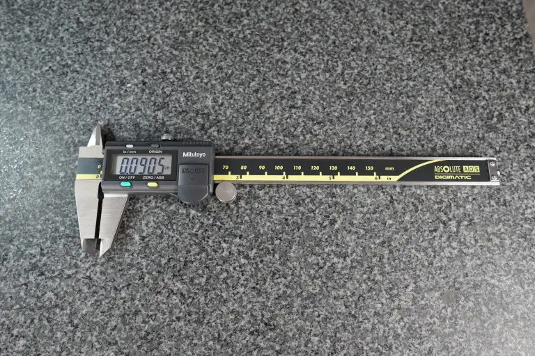
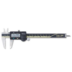
mitutoyo digital caliper
A digital caliper
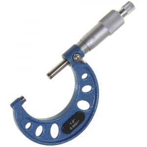
anytime tools 1-2" micrometer
Typical outside micrometer

Basic hand tools including screwdrivers, mallets and deburring tools will get everyday use as well. The real benefit of being a CNC operator is that it can be a great stepping stone to an extremely in demand profession once you have expanded your skillset and advanced to the level of CNC setup and/or programming.

Experience with blueprints, trigonometry or handheld measuring equipment such as micrometers and calipers would be very sought after for any company.

Typical CNC operator job description

MachinistGuides.com is seeking a quality-oriented CNC Machine Operator to join our dynamic team.

The CNC Machine Operator will work with other team members and report to the Shop Manager. This role is responsible for reading blueprints, checking finished parts, and operating CNC mills and/or lathes.

The CNC Machine Operator will:

  • Safely operate a CNC machine to create precision components
  • Read and interpret blueprints, diagrams, sketches, and verbal instruction
  • Maintain pace of production to meet scheduled demands
  • Safely load and unload CNC production equipment
  • Have the ability to lift 50+lbs and stand for several hours

Desired Skills:

  • CNC machine operator/manufacturing experience
  • Thorough knowledge of standard manufacturing concepts, practices, and procedures
  • Have a strong work ethic and a positive attitude
  • Attentive to detail and instruction

Compensation commensurate with experience. A list of benefits which may include paid time off, 401k, medical, dental, life insurance, and/or holidays.

CNC operator skills
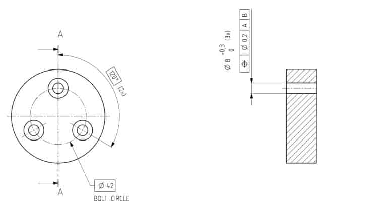
basic dimensions of bolt hole circle on blueprint
Blueprint example
  • Blueprint reading
  • Simple math including addition and subtraction of decimals
  • Hand tools
  • Handheld measuring equipment use
  • Some light trigonometry

Check out our Beginner’s Guide to Blueprint Reading to gain a leg up on the competition. 

Our guide to machinist lingo will help you talk the talk at your new job as well.

How much does a CNC operator make?

20, 10 and 5 dollar bills

According to GlassDoor.com, the average pay for a CNC operator is $38,490 per year. With a typical 40-hour week that comes out to $18.50 an hour.

Keep in mind that pay will vary by region, but this should give you a good idea of where you will start. The nice thing about CNC and machining work is that there is often quite a bit of room for growth.

For reference, CNC programmers can often make $30+ an hour.

How long does it take to become a CNC operator?

Being a CNC operator is an entry level position and as a result, you can be a CNC operator on your first day on the job.

You might not the most productive employee on day one, but you will be tackling the normal everyday responsibilities of more experienced operators.

Is it difficult to learn how to be a CNC operator?

CNC operation is not a difficult job to learn. As an entry level position, the skills needed to be a great CNC operator can be learned in a pretty short amount of time.

Is being a CNC operator stressful?

Generally speaking, CNC operation is not a stressful job. Of course this will vary from company to company but because the position is entry level, there is very little responsibility on the operators part.

It will be possible to find some businesses that work with a very heavy “produce, produce, produce” mentality and in these cases, the job can get more stressful. This is more of a product of the management style than the actual position itself so make sure to do some research online to check out some reviews for any potential employers.

Is being a CNC operator boring?
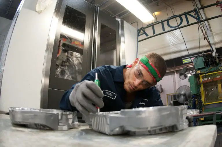
cnc operator inspecting part in front of machine

This is a very subjective question, but I believe many would find the position boring. A CNC operator job will usually be fairly repetitive while not being overly difficult mentally or physically.

The good news is that if your are looking for something to keep things a little more interesting then there will often be opportunities for advancement if you are willing to learn and put in a little effort.

You should also know that boring is also a term for precision machining of a hole by a machine such as a CNC mill or lathe.

Do you need a degree to be a CNC operator?

high school degree

Being a CNC operator does not require a college degree in any form. Local community colleges often offer certificate programs or crash course type coursework that will be looked upon very favorably for any new hire.

Many companies however will require a high school degree or equivalent. Larger companies are usually the ones who have this requirement. Smaller shops are generally more lenient.

What kinds of certifications and training are available to become a CNC operator?

Training, courses, classes, and certifications are available at colleges across the country with many community colleges leading the way.

Check out your local community college’s website to see if they offer training that may be beneficial. You will likely be surprised at the number of different options they offer.

Another valuable resource is your states manufacturing extension program. These organizations are usually aimed more at helping businesses with workforce development, but they often offer subsidized training that can give you a huge leg up in the job market.

YouTube is a great resource as well and there are thousands of high-quality videos out there to teach you all about every aspect of CNC work.

If you want a more structured approach, then check out our post on the best CNC and machining books. Many of these books are the same reference material that the college classes mentioned above will use.

What should you put on a resume to get a position as a CNC operator?

To get a job as a CNC operator make sure to mention any of the following items that may apply:

  • Math skills, especially anything related to trigonometry
  • Blueprint reading experience of any kind
  • Mention your attention to detail
  • Describe how reliable and dependable you are

Tips for finding a good position as a CNC operator

Research, research, research.

Actually it’s not that hard. A single research is probably enough. It is actually pretty easy to find a good job as a CNC operator.

Look for company reviews on sites such as Indeed or GlassDoor. Take it all with a grain of salt but in my experience, any company who has more than a few reviews will be pretty easy to determine the overall “vibe” of the business.

Look for a company that stresses quality over quantity and you will be headed in the right direction.

Related articles

For more information check out these related articles:
Beginner’s Guide to Micrometers – Get Started

A standard outside measuring micrometer

What is a micrometer?

A micrometer is a precision measuring tool. 

They are used in manufacturing, machine shops, automotive work and the construction industry. 

“Mic” is shorthand for micrometer.

Mics are very accurate measuring devices. 

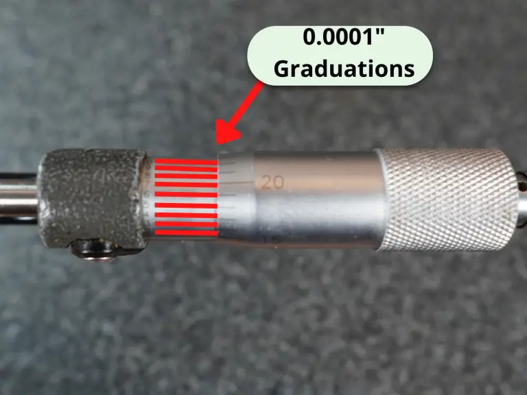
Micrometers are used to take measurements with an accuracy of ~.0001″ or better in inches. 

Measurements in millimeters can be made down to .01mm or .001mm.

How accurate are micrometers?

Most micrometers have an accuracy of +/- 0.0001″, commonly referred to as a tenth of an inch in machining.

The standard metric versions would come as +/- 0.001mm or +/- 0.002mm.

They can be found with worse or better accuracy but what is usually seen .

When to use a micrometer

Three of the most common precision measuring devices used by a hobbyist or a machine shop are calipers, micrometers and dial test indicators. 

Calipers have the least accuracy of the three and the largest measuring range.

Mitutoyo digital caliper

The dial test indicator has the most accuracy and least measuring range. 

Micrometers are in the middle for both accuracy and measuring range. 

While still very accurate, one downfall of the micrometer is that they usually come with a 1″ measuring range (3-4″, 4-5″, etc.).

Because of this they are often sold in sets to cover a larger measuring range. 

A 0-6″ micrometer set will cover the needs of most applications while a 0-12″ set is more than most people, especially hobbyists will need. 0-3″ sets are also common.

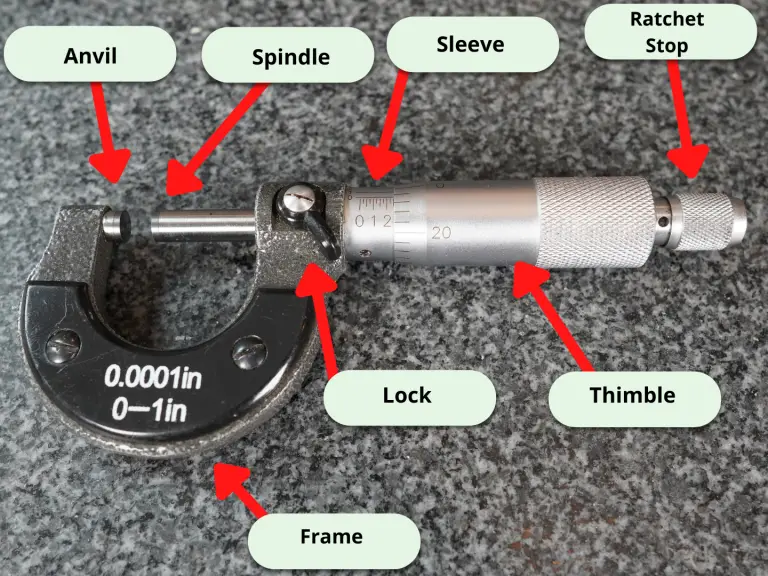
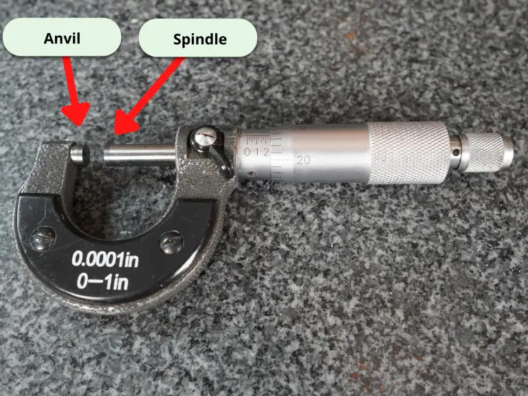
Parts of a micrometer

How to use a micrometer

Before using your micrometer, ensure that the measuring tool and surface to be measured are free of dirt, debris, chips, etc.

Everything should be clean.

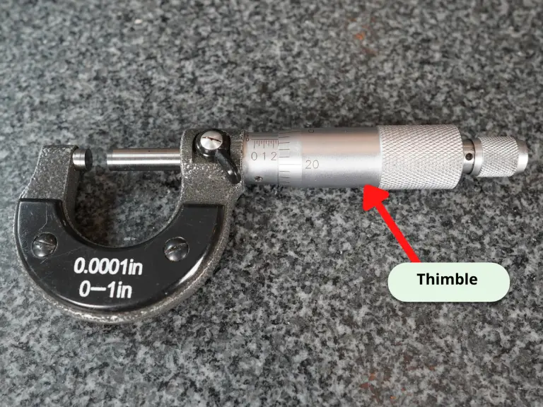
The micrometer thimble should spin freely. No hangs up or anything similar.

Open the thimble to place the part you want to measure between the anvil and spindle.

Spin the thimble until it closes on the part. 

You aren’t trying to clamp down on the part. 

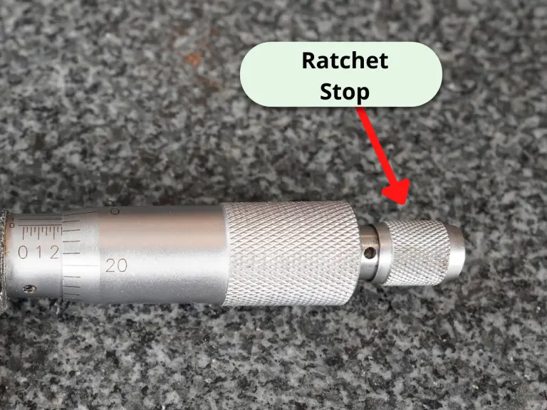
Use a gentle, consistent amount of force when spinning the thimble. Using the ratchet on your micrometer can make this easier. Try spinning the thimble until you get three clicks on your ratchet.

This will help you get repeatable measurements. You want to be consistent in your measuring so you know your readings are good.

This is why taking multiple measurements is so important.

When possible, measure the part multiple times to be confident your readings are accurate.

A little practice on a cheap gauge block can help here. Measure that same gauge block a bunch of times and you will become more repeatable in your measurements. You’ll also see how easy it is to change your reading.

As the spindle closes on the part being measured, it can be beneficial to slightly rock the micrometer in an effort to seat the micrometer on the part.

Be careful: this technique isn’t right for surfaces that could be scratched or damaged easily.

Once you have closed the part in the micrometer, it is time to take your measurement reading.

How to read a micrometer

The most common variety of micrometers measures to one ten-thousandth of an inch (.0001″).

Measurements are taken by identifying where the lines on the micrometer line up.

You will need to take 4 readings and add them together to get your measurement.

These readings are the 0.1000″, 0.0250″, 0.0010″ and 0.0001″ readings.

Machinists refer to these as the hundred thousandths, 25 thousandths, 1 thousandths and lastly the tenths readings.

Let’s get started.

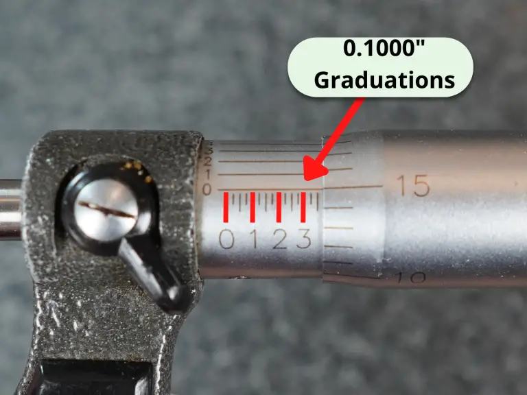
Along the sleeve of the micrometer will be graduations similar to a ruler. The graduations at every fourth interval are most often numbered 0, 1, 2 and so on. 

These numbers represent .100″ or one hundred thousandths of an inch. 

Whichever hundred thousandths reading you are past is your reading. In the pic above, the hundred thousandths reading would be 3 which equals 0.3000″.

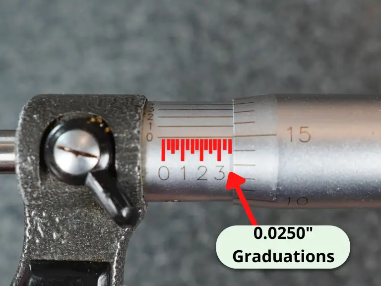
Once you have taken your hundred thousandths reading then you will need to take the 25 thousandths reading.

Each mark along the sleeve is 0.025″ or 25 thousandths.

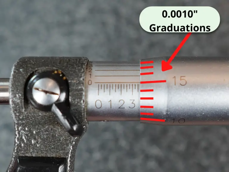
Next is the reading from the thimble. This is the 0.0010″ reading or one thousandth of an inch reading. 

In the pic above two lines are shown past the three so the 0.0250″ graduation value would be 0.0500″.

In the end we are going to add all of our individual measurements up for our final reading.

Note the 0.0010″ reading on the thimble and lastly take the tenths reading from the spindle.

Here we have 15 thousandths.

This makes our measurement so far 0.300″ + 0.0500″ + 0.015″ = 0.3650″.

The last reading to take is the tenths reading. If the lines matched up at the 6 tenths mark, then we would have a reading of 0.0006″ which we need to add to our previous readings.

0.3650″ + 0.0006″ = 0.3656″ or three hundred and sixty five thousandths of an inch and six tenths.

Frequently asked questions about micrometers

What kinds of micrometers are available?

There are a ton of different micrometer types available

Often specific industries have their own special type micrometers such as the auto related micrometers on our list of the most common micrometers below:

  • Outside micrometers – measures various lengths, widths, thicknesses and diameters
  • Inside micrometers – measures hole diameters, slot widths
  • Depth micrometer – measures depth of holes, step locations
  • Thread micrometers – measures various thread characteristics
  • Crankshaft micrometer – specific measuring range for measuring crankshafts
  • Disc brake micrometer – measures thickness of brake rotors
  • Blade micrometer – measures slots, keyways and grooves

Are cheaper micrometers as good as expensive ones?

The cheaper off-brand micrometers have gotten much better in recent year, but they haven’t quite caught up to the best manufacturers yet. 

Starrett and Mitutoyo still reign supreme in terms of quality and accuracy.

You can always look for used options on Craigslist or Facebook marketplace to save a buck.

What makes a good micrometer?

A good micrometer needs two things: precision and accuracy. 

Some adjustments can be made with most micrometers to account for small errors in accuracy but nothing can be done to fix a tool that isn’t precise. 

Quality micrometers will turn smoothly without any drag. This is the telltale sign of a good tool. If your micrometer ever feels like it is rubbing internally, we recommend disassembling the micrometer and cleaning per the manufacturers instructions to eliminate any possible contamination that may be causing the issue

How to adjust a micrometer

If your micrometer is in need of adjustment, most micrometers can be adjusted by using the wrench that came with your tool to spin the sleeve of the micrometer. This is usually done in the zero position. This can be especially useful for adjusting for the touch or feel of a mic when it does not include a ratchet or friction stop. 

If you no longer have a wrench or spanner for adjustment, replacement wrenches can be purchased from most manufacturers or on Amazon.

How often should my micrometer be calibrated?

How often you need to calibrate your micrometer will vary depending on a few factors such as what you are measuring with it, how often you are using it, and what type of environment it is in.

Check out our guide to micrometer calibration to get a better understanding of the how, where, when and why of calibrating your mics.

Related articles

For more information check out these related articles:
Ultimate Guide to Measuring Caliper Sizes

What size do calipers come in?

Dial, digital and vernier calipers come in a large variety of sizes.

On the smaller end of measuring ranges would be a 0-3” caliper, though these tend to be pretty rare. 0-4” calipers sneak in there in small quantities and then by far the most common measuring range of a caliper is 0-6”.

A 0-6” measuring caliper is the typical everyday workhorse of the machine shop.

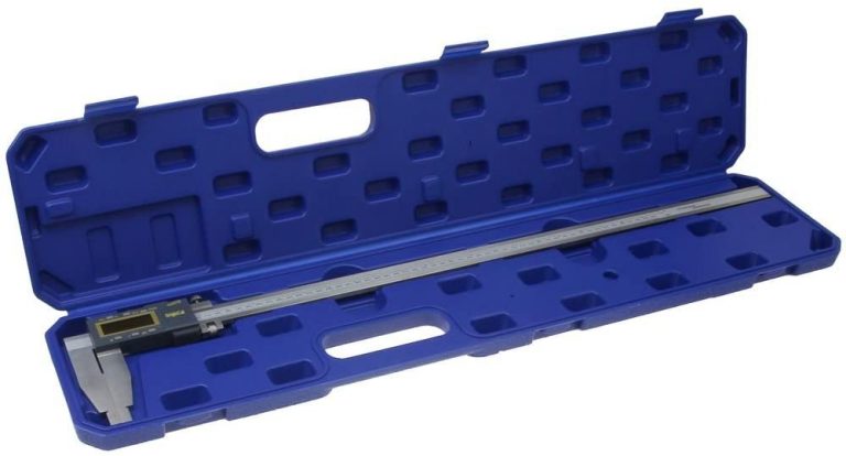
Custom calipers can be made to just about any size measuring range. However, the largest normal calipers are generally 0-24”. I am sure that many people have experience working with larger sets, but they certainly are not what I would call common.

Measuring Range in Inches

Measuring Range in MM

0-3"

0-75mm

0-4"

0-100mm

0-6"

0-150mm

0-8"

0-200mm

0-12"

0-300mm

0-24"

0-600mm

0-40"

0-1000mm

Are there any differences between calipers with small and large measuring ranges?

Measuring Range

Advantages

Disadvantages

Smaller Calipers

Accurate, easier to use

Limited measuring range

Larger Calipers

Can measure larger distances

Less accurate, hard to manuever for measurements, expensive

Accuracy and ease of use would be the primary differences between small and large measuring calipers.

Smaller sets of calipers can get into tight spaces, and they are much easier to maneuver to take your measurements.

Anyone who has tried to measure a smaller dimension with a set of large calipers knows exactly how awkward they can be in that situation.

A 0-6” set of calipers works well for all but the tightest spaces and I recommend using them for all measurements under six inches. This is because not only are the larger calipers unwieldy at times, but they typically sacrifice some accuracy to gain the larger measuring range.

A good set of 0-24” calipers will often be accurate to +/- 0.002” while a good set of 0-6” calipers will be accurate to +/- 0.001”. Extra-large calipers such as any that are over 24” are going to suffer and even bigger hit to their accuracy.

Keep in mind that we are talking about good quality calipers. You can find junk in all sizes, be sure to avoid them.

Below is a table that compares the measuring range of typical high-quality calipers such as those from Starrett and Mitutoyo and their accuracy. Lesser quality tools could easily be half as accurate or less.

Measuring Range in Inches

Measuring Range in MM

Typical Accuracy in Inches

Typical Accuracy in MM

0-3"

0-75mm

+/- 0.001"

+/- 0.02mm

0-4"

0-100mm

+/- 0.001"

+/- 0.02mm

0-6"

0-150mm

+/- 0.001"

+/- 0.02mm

0-8"

0-200mm

+/- 0.001"

+/- 0.02mm

0-12"

0-300mm

+/- 0.001"

+/- 0.02mm

0-24"

0-600mm

+/- 0.002"

+/- 0.05mm

0-40"

0-1000mm

+/- 0.003"

+/- 0.07mm

What is the most common measuring caliper size?

By far the most common size of calipers is 0-6”. Calipers with a 0-12” measuring would be the next most common.

After that, things vary a little bit. 0-24” would be the next logical choice, but many people purchase random in between sizes such as 0-4” or 0-8”. If you have a 0-6” and 0-12” set already, I would definitely recommend a 0-24” set as the next set to own.

Are digital calipers better than dial or vernier calipers?

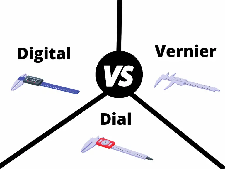
comparison of digital, dial and vernier calipers

No, digital calipers are not better. In fact, they are very similar to dial and vernier calipers. Measuring ranges and accuracy remain similar across all three types of calipers.

This isn’t the case with all manufacturers, so make sure to pay attention to the reported accuracy of any tool you purchase.

We do recommend digital calipers because they are easier for beginners to use and read their measurements accurately but many people prefer the old school route.

Complete Guide to Measuring Caliper Calibration

Calipers are precision measuring instruments that get used for a large variety of types of measurements. Most can measure outside, inside, depth and step measurements. That’s a wide assortment of things they can check for such an accurate tool.

But the question is how do you know you can trust the measurements you get from your set of calipers?

By calibrating them of course! Luckily, we got a thorough guide to take you through the ins and outs of calibrating your calipers. We included the hows, the whys, the what fors and most importantly, the actual steps you need to take calibrate your calipers.

Keep reading our guide to become a true caliper calibration connoisseur.

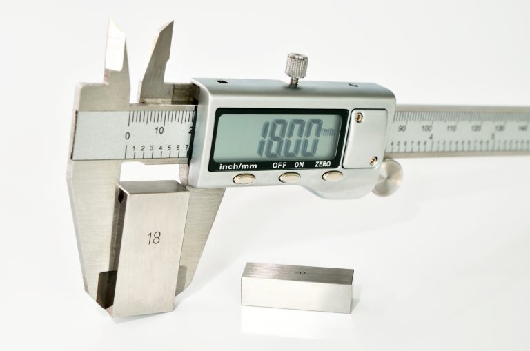
digital caliper measuring gauge block
Reading right on the money

Why do calipers need to be calibrated?

Calipers, including both dial and digital versions, get used for all types of precision measurements from engine work to reloading. It should be easy to see that these aren’t the type of measurements you want to get wrong.

For this reason, it is important to calibrate your calipers and ensure the readings you get are indeed correct. Calibration will allow you to verify that your caliper is accurate for all the measurements it can take and to top it all off, calibration isn’t that difficult. Simply follow our step-by-step guide below.

How often should you calibrate your calipers?

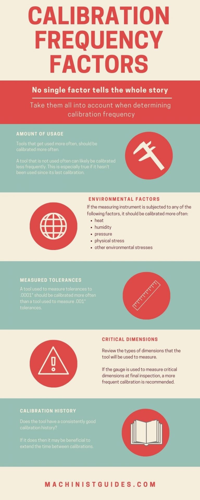
Before we get to the procedure for calibrating your calipers, there are some important factors to consider. The visual below lists some of the most common factors that affect how often you should calibrate your calipers.

calibration frequency infographic

Calipers can be calibrated at many different intervals. When setting the calibration frequency, you should take into account factors such as:

  • How the tool will be used? Will the caliper be used to measure critical dimensions?
  • How tight are the tolerances it will be used to measure?
  • Will it be subjected to stresses such as heat, humidity, pressure, physical stress or other environmental?
  • Will it get used often?
  • Does it have a calibration history and if so, has it been consistent?

The best practice is to take all of these factors into consideration and set how often you often the tool will be calibrated.

If a caliper is taking important measurements often, the calibration interval will often be 3-4 months or possibly more often. When they don’t get used frequently or the measurements they are used for are less critical, then they can be calibrated once a year or less often.

It all depends on what works for you or your shop. If you are unsure of where to start, calibrate more frequently and then adjust based on usage and how well the tool holds its calibration over time.

What equipment do you need to calibrate your calipers?

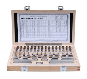
gauge block set
starrett tool and instrument oil bottle with cap
Tool oil

Calibrating a set of a calipers requires a known standard such as a set of gauge blocks. This standard gets used to compare the measurement readings

Additional supplies such as gage oil and task wipers will also come in handy but aren’t required.

Choose gauge blocks that are at least four times more accurate than the accuracy of your caliper. This is easy to achieve with your average caliper.

Most calipers are accurate to a thousandth of an inch (“thou”) or 0.001”. This means you need a set of gauge blocks that are accurate to 0.00025” (two and a half tenths).

This 4:1 requirement started with the military specification, or mil spec MIL-STD-45662. This specification defined the calibration requirements for companies.

This requirement is a minimum requirement. Using gauge blocks that are 10 times more accurate than the caliper is even better and common practice in many machine shops.

Do you need to buy a caliper that is already calibrated?

No, there is no need to buy a pre-calibrated caliper. The difference between verifying a caliper is accurate and calibrating it is small. Because you will need to verify the accuracy of the tool when you get it anyways, it is best to take a few extra steps and calibrate the tool.

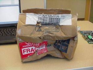
One reason why pre-calibrated tools are not recommended is shipping companies. Pretty much everyone has had a package destroyed by the delivery service. What can happen is the tool will get calibrated and then shipped to you. In the process of shipping, your precision measuring instrument is dropped, kicked, maybe even dropkicked across the country to your doorstep.

Physical abuse can cause the tools calibration to be affected. For this reason, it is best to check the caliper yourself and know that from the point you received it, it was accurate.

box damaged in shipping
Handled with care

What do you need to maintain for calibration records?

At a minimum, your records should include calibration labels for your tools and a database where you record calibration information.

Your calibration records don’t need to be anything too fancy. Labels or stickers to place on your tool and a place to record the calibration data such as measurement values, dates, tool number, etc. This calibration database can be something as simple as a notecard system or full-blown calibration management software.

If the caliper is for personal use only then you may find that you don’t need the records or labels at all, though it can be handy to have the records for reference even if they only get jotted down into a notebook.

What information should the calibration label include?

calibration label
Example calibration label

Calibration labels should include at least the calibration date along with the next calibration due date. It is also a good idea to include the initials of the person who calibrated the tool and the tool #.

Note: Sometimes it isn’t practical to place a calibration label on the tool itself. If this is the case, it can be acceptable to place the label on the case of the tool. However, when possible, the label should be on the tool.

What information should be included in the calibration database?

The calibration database can come in many forms. Card systems, spreadsheets, database files and specialty programs are often used to maintain calibration records.

The following information should be recorded in the calibration database:

  • Who performed the calibration
  • Date calibration was performed
  • Master standard that was used for calibration (gauge block set #)
  • Calibration checks to be performed
  • Acceptable limits for calibration checks
  • Actual readings from the calibration checks
  • Next calibration due date

While it isn’t always a strict requirement, it is a good idea to think about recording the environmental conditions such as temperature and humidity when performing your calibration.

Example calibration procedure for a dial or digital measuring caliper

  1. Read the entire procedure before beginning calibration
  2. If at any time in the calibration procedure a problem is identified, the problem will be corrected and the process will start over. If the problem cannot be fixed, the caliper will be taken out of service.
  3. Check accuracy with gage block(s) having accuracy not less than 0.00025”. Verify measurements at sizes that are not even intervals. Use sizes such as .206”, 1.456” or 4.784”. Avoid common sizes such as .250”, .500” and .800”.
  4. Close the O.D. jaws and inspect for damage. Hold the calipers to a light source and inspect for light between the jaws. Jaws which are misaligned will not be parallel and create a gap between the jaws which is easily detected with backlighting.
  5. Verify the zero setting by taking a reading when the O.D. jaws are in the fully closed position. If the caliper does not read 0.000”, zero the calipers.
  6. Verify the accuracy of the O.D. jaws by checking known standards such as a set of gage blocks at intervals across the entire measuring range. Measuring at 1.000”, 2.000”, etc. is acceptable, but it is preferred to verify measurements at irregular intervals such as .754”, 3.345”, 5.687”, etc.
  7. Record your readings in the calibration database.
  8. Repeat steps 3 through 7 for both the I.D. jaws and depth measuring rod if present on your caliper. Instead of checking the O.D. jaws for damage, check the I.D. jaws and the depth measuring rod.

PL on Blueprint – What It Means and Compared to Similar Callouts [With Examples]

What does PL mean on an engineering or manufacturing blueprint?

PL is an abbreviation for places. This notation will be shown with a number associated with it such as:

Chamfer 0.010” x 45 degrees 4 PL

When the PL note is used, it should be very clear what feature, edge, etc. that the callout applies to. Unfortunately, what was obvious to the person drafting the print and what is obvious to the person down the line reading it, does not always match up.

When in doubt ask the customer or someone higher up the food chain.

PL example on a blueprint

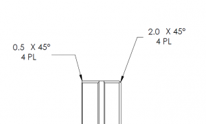
The example below shows two chamfer callouts that use PL notation. 

manufacturing blueprint that shows two chamfers with PL callouts

This is just a section of the blueprint but the overall part shape is square. The 4 PL refers to the 4 edges on each side there the main surface (S1 & S2) meet the sides of the part. 

Therefore the part should be chamfered at 0.5 x 45° all around on one side and 2.0 x 45° on all around on the other side.

Blueprint notes that are similar to PL

The #x format (2x, 4x, etc) gets used often in place of the places note. The PL example given above could be changed to either of the following and the requirement would remain the same:

Chamfer 0.010” x 45 degrees 4x or Chamfer 4x 0.010” x 45 degrees

Want to learn more?

GD&T is a complicated subject and understanding it correctly can be the difference between a perfect part and scrap.

The best way to learn GD&T is from experienced teachers who can break down the material into manageable pieces.

Luckily, we know someone.

And MachinistGuides.com readers get an exclusive discount on training!

Related articles

// Symbol on Blueprints [What It Is, How To Check It & More]

What does the // symbol mean on a blueprint?

Parallelism Blueprint GD&T Symbol two parallel lines
The GD&T symbol for parallelism

// is the GD&T symbol for parallelism. For the parallelism symbol, notice how the two lines of the symbol run together. They are parallel to each other. 

How to read a parallelism blueprint callout

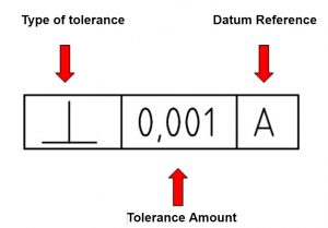
The blueprint item that contains the parallelism callout is called a feature control frame.

The components of a feature control frame are shown below.


feature control frame description with parts identified

The parallelism symbol would be inside the first box to indicate the type of tolerance.

The tolerance amount is listed in the middle box. This tolerance is in the the same units that the rest of your blueprint is in. Many times this will be listed in general tolerance block of the blueprint.

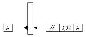
The datum reference is the feature that the feature with the parallelism callout will be compared to. In the example below, datum A is on the left and the right side has the parallelism callout attached to it. 

This feature control frame reads “the right side of the part must be parallel within 0.02 to datum A”.

parallelism callout with feature control frame

How to check for paralleism

Other GD&T symbols

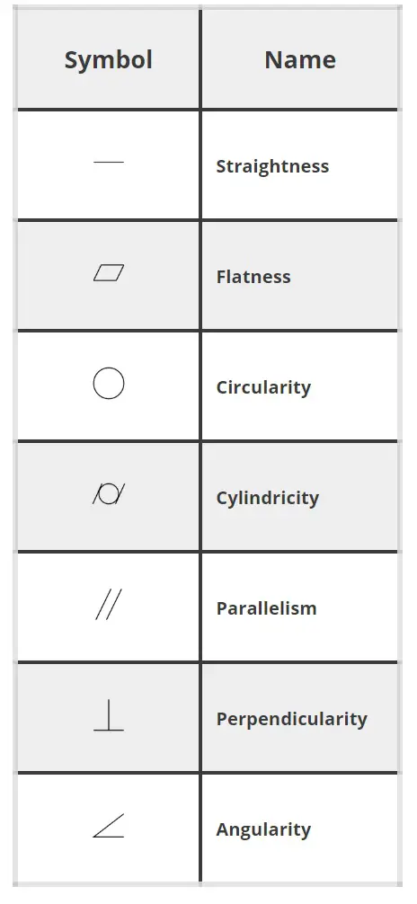
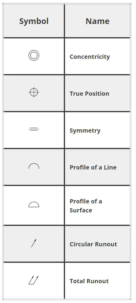
GD&T symbols are used to control the size, form and/or orientation of the different features on a part. 

Check out the list below to learn about other GD&T symbols and if you want a more in depth guide that includes then check out our Complete Guide to Blueprint Symbols

gd&t symbols
gd&t symbols

Related articles

GD&T is a complicated subject and understanding it correctly can be the difference between a perfect part and scrap.

The best way to learn GD&T is from experienced teachers who can break down the material into manageable pieces.

Luckily, we know someone.

And MachinistGuides.com readers get an exclusive discount on training!

Want to learn more?

26 Types of Micrometers [Includes Pictures & Descriptions]

Micrometers come in many shapes and sizes. 

Our comprehensive list covers all of the most common and many uncommon micrometers found in machine shops, garages and workshops around the world.

Read on to see how many you’ve used or how many you even knew existed.

The most common types of micrometers

Outside micrometers

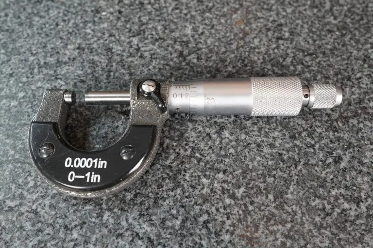
anytime tools 1-2" micrometer
Anytime Tools 1-2" Outside Micrometer

Otherwise known simply as mics. Your standard everyday micrometer. Used for measuring outside diameters, lengths, widths, thickness, etc. Commonly available in 1” measuring ranges.

The typical accuracy of an outside micrometer is 0.0001”.

Inside micrometers

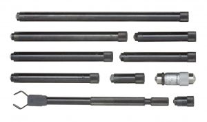
mitutoyo inside micrometer set
Mitutoyo Inside Micrometer Set

Used for checking internal widths, diameters, and bores. The typical accuracy of an inside micrometer is 0.001”.

Depth micrometers

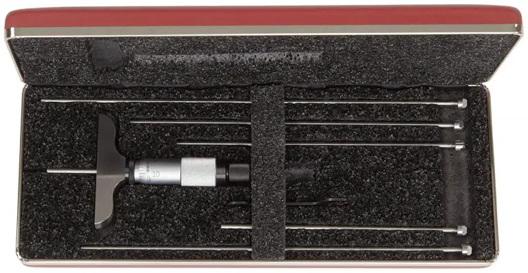
Starrett Depth Micrometer

Used for measuring the depth of slots and holes as well as the location of various steps. They tend to be less accurate than a standard micrometer. Most will have an accuracy of +/- 0.001”.

Styles of micrometers

Standard vernier micrometer

The old standby. This type of micrometer has been produced for decades and I’m sure will continue to be around for many more years.

They feature a rotating thimble that has a vernier scale wrapped around it. This scale is matched up with the scale on the sleeve to obtain your measurement.

Digital micrometer

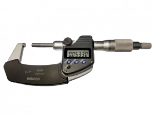
mitutoyo digital micrometer
Mitutoyo Digimatic Digital Micrometer

Many of the micrometers listed are available as a digital version as well. Do not expect anything different between a digital and standard micrometer other than the display.

They have the same accuracy. Digital vs non digital is just a matter of preference.

Mechanical counter/digital mics

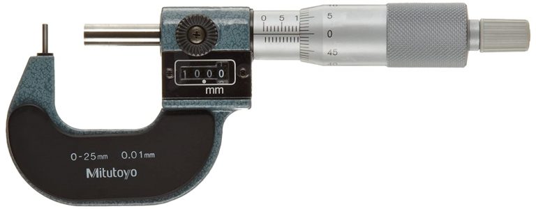
mitutoyo mechanical counter micrometer
Mitutoyo Digital Counter Micrometer

A less popular option, some of the micrometers listed can be purchased as a mechanical counter version. Some of the manufacturers call them digital, but the term is misleading.

Personally, I have never found them superior to other mics. I would avoid them. You can expect their accuracy to be in line with a standard micrometer of the same type.

Micrometer sets

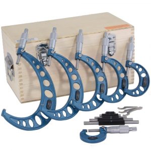
anytime tools micrometer set with case and reference standards
Anytime Tools Micrometer Set

Because micrometers have a smaller measuring range when compared to some other precision measuring tools such as calipers, they are often purchased as a set. Micrometer sets are commonly available in 0-3”, 0-6” and 0-12” varieties with many other less common sets being available as well.

Micrometers with different spindles and/or anvils

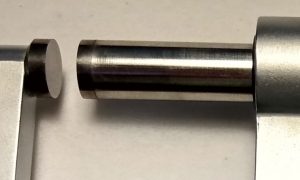
Carbide tipped anvil and spindles

Carbide tips provide additional wear resistance for a micrometer, especially one that may see extra heavy usage. While they can be useful in this regard, the carbide tips are more brittle and have been known to chip.

For most people, your standard stainless-steel spindle and anvil will be good enough but both types work well.

Non-rotating micrometers

These micrometers work well for a number of applications. The spindle on this type of micrometer doesn’t spin to increase the accuracy of the measurement. It also has the added benefit of being less likely to damage surfaces where surface finish is extremely important.

Micrometers with rounded anvils

These micrometers allow you to measure features that are not flat such as the wall thickness from the edge of a hole another surface.

Micrometers with interchangeable anvils

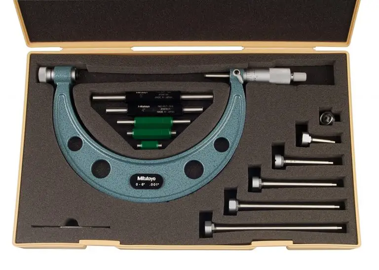
mitutoyo interchangeable micrometer
Mitutoyo Interchangeable Anvil Micrometer Set

Often seen on large micrometers. Interchangeable anvils usually allow a single micrometer to measure over a 6” range in 1” increments.

Imagine a 12” micrometer that can swap anvils to measure any 1” range up to 18” and you will get the idea.

Blade micrometer

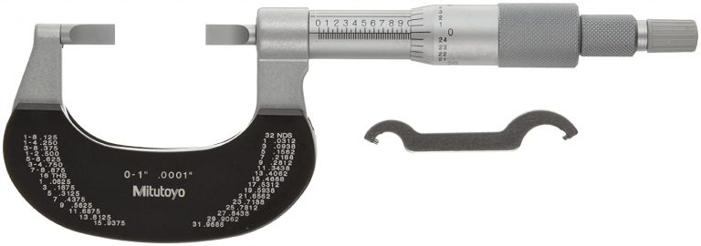
mitutoyo blade micrometer
Mitutoyo Blade Micrometer

Blade micrometers are used for measuring narrow features such as grooves, slots and keyways. The spindle of a blade micrometer won’t rotate to allow accurate alignment and measurement of your part.

V anvil micrometer

These micrometers are used to check for an out of round condition, sometimes called lobing. They are often used in the centerless grinding industry.

Tube micrometer

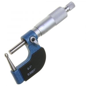
anytime tools tube micrometer
Anytime Tools Tube Micrometer

Used almost exclusively for measuring the wall thickness of round objects such as…you’re never going to guess.

Alright, I’ll tell you. They measure tubes! Surprising, I know!

The anvil on these micrometers is more rounded than what you would see on a micrometer with rounded anvils

Pitch-diameter micrometer

These micrometers have a special anvil and spindle to allow them to measure the opposite sides of a thread. The anvil has a double v shape while the spindle is pointed.

They have an overall measuring range such as 0-1” or 1-2” like a standard micrometer but also have a range of threads per inch or mm that they are capable of measuring.

Multi-anvil or universal micrometers

Starrett Mul-T-Anvil Micrometer

These micrometers allow you to switch the anvil so that the tool can take multiple types of measurements. One multi-anvil mic can take the place of an outside, tube and rounded anvil micrometer all in one.

Groove micrometers

Groove micrometers are used for taking measurements of grooves and other small features. Their low profile allows them to be used in tight spaces.

Disc micrometers

fowler disc micrometer
Fowler Disc Micrometer

This type of micrometer is frequently used for measuring thin sections of a part such as a sheet of material or the ribs or fins on a component. Often, they come with non-rotating spindles to keep the thin material from being twisted and giving an incorrect measurement.

Micrometers with special frames

Micrometers with insulated frames

outside micrometer

Heat can cause metal or other materials to expand. When this happens, your part can appear to measure larger than it actually is. The same principle affects your measuring tool as well. This is why many micrometers will have an insulated grip to keep you from transferring your body heat to the micrometer and affecting the measurements.

Bench micrometer

Bench micrometers work like a combination micrometer and micrometer stand. They are used when the part to be measured can be brought to the workbench and will provide all the same benefits of using a good quality micrometer stand.

Sheet metal micrometers

mitutoyo sheet metal micrometer
Mitutoyo Sheet Metal Micrometer

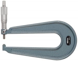
Sheet metal mics will allow you to take a measurement away from the edge of the material. Useful for working with, well sheet metal duh but also other materials where you want to get closer to the center of the part and need the clearance to be able to do it.

Hub micrometer

Hub micrometers are used when a shallow frame is needed such as when you need to insert the tool into a hole to take a measurement.

Micrometer head

mitutoyo micrometer head
Mitutoyo Micrometer Head

Micrometer heads don’t have a body or frame. They are used for all sorts of applications where an adjustment needs to be made with a great deal of accuracy.

Some common uses are for in fixtures as well as machine setup.

Special application micrometers

Crankshaft micrometer

A specialized set of micrometers that have a larger than normal measuring range that allows them to take measurements you might need when working with crankshafts.

This range is typically from 1 ½” to 3 ½”.

Disc brake micrometer

Another special application micrometer. They are used for measuring the depth of the grooves in your brake rotors. Like the sheet metal micrometers, they have a frame that allows measurements farther away from the edge of the brake rotor.

Paper gage micrometer

Used in the paper and printing industries, these micrometers feature wider spindle and anvils that help keep them from compressing the material being measured to make sure the readings are accurate.

Micrometer accessories

Micrometer balls

starrett micrometer ball
Starrett Micrometer Ball

This attachment allows a standard outside micrometer to function like a tube or rounded anvil mic. The attachments do reduce the overall measuring range of your tool so keep that in mind.

Additionally, you will need to subtract the size of the micrometer balls into consideration when calculating your measurement.

Micrometer stands

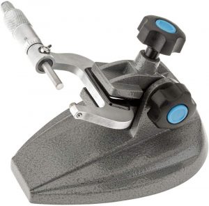
grizzly industrial micrometer stand holding micrometer
Micrometer Stand Holding A Micrometer

Micrometer stands can give you a third hand when using your micrometer. While they work well to give you more freedom for maneuvering your part, they also help to reduce any heat transfer to the micrometer which could affect your measurement.

Related articles

For more information check out these related articles:
Bilateral Tolerance Guide [Examples & Explanation]

What is a bilateral tolerance?

A bilateral tolerance is a plus or minus tolerance (+/-). It allows variation from the nominal size in both a positive and negative direction. 

In most cases, the bilateral tolerance will be specified as equal in both directions such as 10.0mm +/- 0.5mm.

This is not always the case though and a bilateral tolerance does not need to have equal positive and negative tolerances. 10.0mm +0.2mm/-0.3mm would be an acceptable bilateral tolerance as well.

Here are some quick bilateral tolerance examples:
  • 5.5″ +/- 0.25″
  • 5.5″ +1.0″/-0.5″
  • 25.5mm +0.1mm/-0.2mm
  • 30.6mm +/- 0.3mm

Notice that in each of the examples there is allowed variation (tolerance) from the nominal size in both directions.

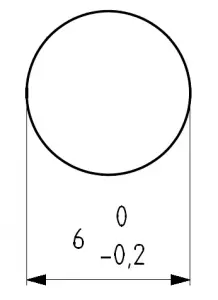
A tolerance of 25.5mm +0/-0.2mm would not be a bilateral tolerance because it has no tolerance in the positive direction. This would be an example of a unilateral tolerance.

Bilateral tolerance symbol

There is no GD&T symbol for a bilateral tolerance.

Per ASME Y14.5, the notation for a bilateral tolerance is to show a plus and a minus tolerance associated with a nominal dimension and neither of them is a zero.

Want to learn how to type GD&T symbols with no special fonts needed?

How to read a bilateral tolerance

Let’s start with our examples from above

  • 5.5″ +/- 0.25″
  • 5.5″ +1.0″/-0.5″
  • 25.5mm +0.1mm/-0.2mm
  • 30.6mm +/- 0.3mm

Now let’s break it down so you can see what the nominal size is as well as the top and bottom ends of the tolerance zone.

Nominal Size

Bottom of Tolerance

Top of Tolerance

5.5"

5.25"

5.75"

5.5"

5.0"

6.5"

25.5mm

25.3mm

25.6mm

30.6mm

30.3mm

30.9mm

Bilateral tolerance examples

Types of bilateral tolerances

Equal bilateral tolerance

bilateral tolerance blueprint example
An example of an equal bilateral tolerance

An equal bilateral tolerance will have equal plus and minus tolerances such as 6.35 +/- 0.025 as shown in the example above. 

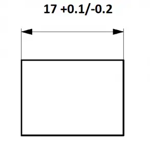
Unequal bilateral tolerance

An example of an unequal bilateral tolerance

An unequal bilateral tolerance will have plus and minus tolerances that are not the same and neither is zero such as 17.0 +0.1/-0.2 as shown in the example above.

Bilateral tolerances compared to other tolerance types

Bilateral tolerance vs unilateral tolerance

A bilateral tolerance allows a tolerance in both directions.

A unilateral tolerance allows a tolerance in only one direction.

A bilateral tolerance is plus AND minus tolerance. A unilateral tolerance is a plus OR minus tolerance.

Here are some examples of unilateral tolerances:
  • 10.0mm +0/+0.5mm
  • 5.515″ +0.010″/+0.015″
  • 2.325″ +0/-0.005″
  • 4.5mm -0.2/-0.3mm

Bilateral tolerance vs limit tolerance

A bilateral tolerance specifies a nominal size and a plus/minus tolerance. These values are used to determine the tolerance range for a feature.

A limit tolerance skips the calculation step and simply gives you the tolerance range.

The table below shows bilateral tolerances with their equivalent limit tolerances.

Bilateral Tolerance

Limit Tolerance

10.0 +/-0.5

9.5 - 10.5

5.525 +0.025/-0.050

5.475 - 5.550

7.55 +/+0.15

7.40 - 7.70

2.324 +0.005/-0.010

2.314 - 2.329

Want to learn more?

GD&T is a complicated subject and understanding it correctly can be the difference between a perfect part and scrap.

The best way to learn GD&T is from experienced teachers who can break down the material into manageable pieces.

Luckily, we know someone.

And MachinistGuides.com readers get an exclusive discount on training!

Related articles

Unilateral Tolerance Guide [Examples & Explanation]

What is a unilateral tolerance?

Basically, a unilateral tolerance is a type of tolerance that is only allowed in one direction. Either an all plus tolerance or an all minus tolerance.

Here are some quick unilateral tolerance examples:
  • 10.0mm +0/+0.5mm
  • 5.515″ +0.010″/+0.015″
  • 2.325″ +0/-0.005″
  • 4.5mm -0.2/-0.3mm

Notice that in these examples, all of the allowed size variation is in one direction. The direction can be positive or negative and zero is allowed.

Unilateral tolerances are often used to specify dimensions that require a specific fit with a mating part.

unilateral tolerance blueprint example
Unilateral tolerance shown on a blueprint

Unilateral tolerance symbol

There is no GD&T symbol for a unilateral tolerance.

Per ASME Y14.5, the notation for a unilateral tolerance is to show a plus or a minus tolerance associated with a nominal dimension. It is acceptable for one of the specified tolerances to be zero.

Want to learn how to type GD&T symbols with no special fonts needed?

How to read a unilateral tolerance

Let’s start with our examples from above. 

  • 10.0mm +0/+0.5mm
  • 5.515″ +0.010″/+0.015″
  • 2.325″ +0/-0.005″
  • 4.5mm -0.2/-0.3mm

Now let’s break it down so you can see what the nominal size is as well as the top and bottom ends of the tolerance zone.

Nominal Size

Bottom of Tolerance

Top of Tolerance

10.0mm

10.0mm

10.5mm

5.515"

5.525"

5.530"

2.325"

2.320"

2.325"

4.5mm

4.2mm

4.3mm

Regardless of what the nominal size is, the requirement for each of these unilateral tolerance examples would be that the dimension must fall within the top and bottom tolerance range. 

Unilateral tolerances compared to other tolerance types

Unilateral tolerance vs bilateral tolerance

unilateral tolerance blueprint example
A unilateral tolerance example

A bilateral tolerance allows a tolerance in both directions.

A unilateral tolerance allows a tolerance in only one direction.

A bilateral tolerance is plus AND minus. A unilateral tolerance is a plus OR minus tolerance.

If we take the unilateral tolerance from the picture above and convert it to a bilateral tolerance it could be either:
  • 39.75 +/- 0.25
  • 39.7 +0.3/-0.2
  • 39.6 +0.4/-0.1

Notice that the important feature of the tolerance is that it has both a positive and negative tolerance. Neither side of the tolerance is zero.

Unilateral tolerance vs limit tolerance

A unilateral tolerance specifies a nominal size and a plus or minus tolerance. These values are used to determine the tolerance range for a feature.

A limit tolerance skips the calculation step and simply gives you the tolerance range. Instead of a nominal size and a tolerance, the top and bottom of the tolerance range are directly listed.

Let’s compare some unilateral and limit tolerances to see how they differ:

Unilateral Tolerance

Limit Tolerance

10.0 +0/-0.5

9.5 - 10.0

5.525 +0.025/+0.050

5.550 - 5.575

7.55 +0/+0.15

7.55 - 7.70

2.324 -0.005/-0.010

2.314 - 2.319

What is a unilateral tolerance used for?

A unilateral tolerance is most often used to specify a tolerance associated with a specific fit such as a clearance fit or interference fit.

Want to learn more?

GD&T is a complicated subject and understanding it correctly can be the difference between a perfect part and scrap.

The best way to learn GD&T is from experienced teachers who can break down the material into manageable pieces.

Luckily, we know someone.

And MachinistGuides.com readers get an exclusive discount on training!

Related articles

Ultimate Guide to Measuring Caliper Accuracy

Measuring calipers can be extremely capable measuring devices when in the right hands.

Knowing the limitations of your calipers and how you affect them is what will make you the “right hands” for the job.

I’m going to run you through the different aspects that affect caliper accuracy. I’ll start with the most basic topics and work from there so feel free to skip ahead if you already know about a subject.

Size of calipers

0-6" calipers

mitutoyo digital caliper
0-6" Mitutoyo Digital Caliper

The most common type of measuring caliper is a 0-6” caliper. If you are working in metric, this will be a 0-300mm caliper.

There is some variety in what they are capable of but in general they will be able to measure inside, outside and depth measurements over a 6” measuring range.

Larger and smaller calipers

Calipers do come in many different size measuring ranges. They are used much less often but you will still run into them.

0-12” calipers are the next logical choice when it comes time to measure a bigger part. The reason you wouldn’t use them all the time is because they are big and can be awkward to use.

0-24” calipers have the same issue and are even more awkward. Typically, you would only use the larger calipers in a situation where you could not use a caliper.

There 0-4” and 0-8” varieties that can be found as well and all types of specialized measuring ranges can be special ordered.

0-24" Calipers

Larger calipers will be more expensive than small calipers. The added expense is for accuracy. It gets much harder to maintain the accuracy seen in smaller calipers over larger measuring ranges.

Note: Calipers with larger measuring ranges tend to be less accurate. For example, the same Mitutoyo caliper in a 0-6” version has a specified accuracy of +/- 0.001” and the 0-24” version has an accuracy of +/- 0.002”. They are only half as accurate. This only gets worse when you realize larger calipers from lesser known manufacturers may be even less accurate.

Types of calipers

There are three main types of calipers. They are very similar with the main difference being how the actual measurement is read.

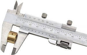
Vernier calipers

vernier caliper measuring thickness of brass part
Vernier Caliper Scale

Often referred to as simply “verniers”, these calipers have multiple scales on the face of the tool that are used together to take your measurement reading.

Because they do not have any internal mechanisms, they are the most durable type of caliper and most likely to remain accurate.

Verniers are the most difficult type of caliper then it comes to reading a measurement, especially for beginners. While they are not necessarily difficult to use, they take a little more understanding than using a dial or digital caliper.

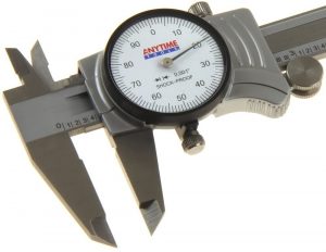
Dial calipers

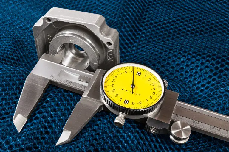
anytime tools dial caliper dial face
Dial Caliper Face

Dial calipers use a geared system to spin a needle on a dial. They have an easy to ready scale on the body of the caliper. This scale is often in .100” increments. The distance between the rulings makes them easier to read compared to the small lines which are used on a vernier.

The scale reading is used with the reading from the needle on the dial face of the tool to calculate your measurement.

Dial and vernier calipers are very similar in cost. Both do not require batteries which means they are always ready to take a measurement.

Digital calipers

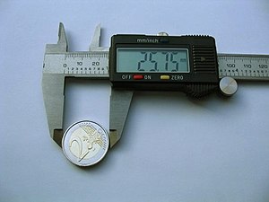
digital caliper measuring coin
Digital Caliper Display

Digital calipers use electronic sensors to give a measurement reading. They are easily the simplest caliper to take a reading with.

The values get read off the LCD display like an alarm clock.

At one time they were very expensive and still somewhat are. In recent years, they have dropped in price and gotten more reliable. Tools made in China and other lower labor cost countries have improved in quality, though they can be hit or miss when compared to established tool and gauge companies.

There are many digital calipers available which are not nearly as accurate as they would lead you to believe. This is because their resolution is finer than their accuracy.

Typical accuracies for different types of calipers

A caliper should be accurate to .001”. There are cheap ones or shoddy quality ones that will fail to meet this accuracy but when most people think about calipers, they expect it to be accurate to .001”.

Accuracy is similar across the different types of 0-6” calipers and it may look like digital calipers have better resolution but that isn’t exactly true.

Often digital calipers will have displays that read out farther than they are accurate to. There isn’t any point taking a reading to 5 tenths of an inch or .0005” if the tool isn’t accurate to that level.

Be careful. Some digital calipers will make you think they are more accurate than they actually are.

How cost affects accuracy

Small calipers are easier to make than large ones at the same accuracy. To get a caliper accurate to .001” at 6” will be much easier than at 24”. This is why the cost goes up quickly for larger calipers or their accuracy goes down.

Some calipers will sacrifice accuracy to keep costs down. Some budget level calipers do not meet an accuracy of +/- 0.001” for a 0-6” caliper. Pay attention to the specified accuracy when comparing different tools.

Keep in mind that if something seems too good to be true then it probably is such as a cheap, large range caliper that claims accuracy to +/- 0.001”.

What tools are more accurate than a measuring caliper?

outside micrometer

Micrometers are another tool frequently used by people who also use calipers to take measurements. The typical accuracy of a micrometer is a tenth of an inch or .0001”. This is 10x more accurate than a caliper.

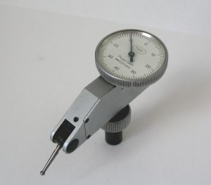
Dial and test indicators are another type of tool used in machine shops. They usually have dial faces with a needle, or occasionally you will find digital versions.

The accuracy of these indicators varies from .001” for many dial indicators to .00001” for test indicators. Test indicators can be 1000x more accurate than dial indicators and calipers.

dial indicator
Dial Test Indicator

Accuracy vs resolution

Resolution is the how finely your tool will give for a reading. It is not how accurate it is.

Imagine you measure a box.

A less capable digital caliper may measure the length of the box at 6.5005”. The problem is that the caliper may only be accurate to +/- 0.001”. This means you could take that same caliper and measure the same box again, in the same exact location and get a reading of 6.4995” or 6.5015”

Tips for increasing your accuracy using calipers

Know what accuracy you need

The first step is knowing how accurate of a tool you need. You might not need a caliper at all. You might need a micrometer to measure down to a tenth (0.0001”). Maybe you can get away with using a good tape measure.

I don’t know. Only you can decide what accuracy you will need.

General advice would be to get a caliper with an accuracy of +/- 0.001” or better.

Be careful how you hold your caliper

You affect the accuracy of your caliper a lot.

You want to make sure that the jaws of your caliper sit flat when you take a measurement. If they are cock-eyed when you use them, the readings will be larger than the actual size.

Luckily, for outside measurements, such as the length or width of a part, this is easy to do. You can gently rock, again I said gently, and you will feel the caliper settle in when it sits flush.

Inside measurements are slightly more difficult because the jaws do not have a flat spot to settle into. Still, you will want to use the same rocking motion, but be even more careful with it.

Repeatability

No matter what type of measurement you plan to take, take multiple readings to develop an assurance that your measurement is accurate. It is not uncommon to take a measurement and get a reading, only to take two more measurements that are both 0.005” off.

At this point you would want to take more measurements to verify that your first measurement was indeed wrong. Maybe it was dirt, or you had the tool at an angle. Either way, verifying your repeatability will help you take more accurate measurements.

Depth measurements are easy to get wrong

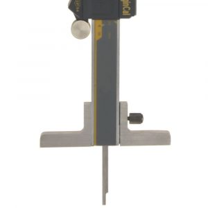
caliper depth base attachment
Caliper With Depth Attachment

Outside and inside measurements aren’t too bad but depth measurements are where things get tricky.

Not all calipers will have the ability to take depth measurements. However, for those that do it is easy to get bad readings when using them to take depth readings.

The shape of the caliper makes them top heavy which means they have a tendency to want to tilt. If your tool moves even just a small amount, it will throw your measurement off by quite a bit.

There are attachments that you can get for your caliper to help steady your tool when taking depth measurements, but they are not a perfect solution.

Another factor affecting accuracy is that the depth measuring rod on a caliper can easily get bent or otherwise out of alignment. This is a common occurrence and even brand-new calipers can come from the factory unable to make accurate depth measurements.

Depth measurements are the most difficult type of measurement to take with a caliper and also the most difficult aspect for a tool maker to build accurately.

Be consistent with your measurements

The amount of force you use when taking measurements with your calipers will change your readings. This is called your “touch”.

If you take a measurement using a small amount of pressure on the caliper and then do the same measurement squeezing the caliper shut and holding it with some force, you will see that your readings can easily vary by a thousandth or two (0.001”-0.002”).

The easiest way to practice being consistent with the force you use to take measurements is to check the same thing over and over.

Checking the accuracy of your caliper

Cheaper calipers can be accurate, but not every cheap caliper will be. Premium tools from Mitutoyo, Starrett or other well-known manufacturers can be off too, but the odds are much less likely.

The problem is that you won’t know the caliper is accurate until you check it. This process is called calibrating. If you don’t have access to everything you need to calibrate a caliper, a less precise version of the process would be called zeroing.

Zeroing your caliper

Zeroing your calipers requires you to close them all the way and reset the zero point.

Zeroing procedure

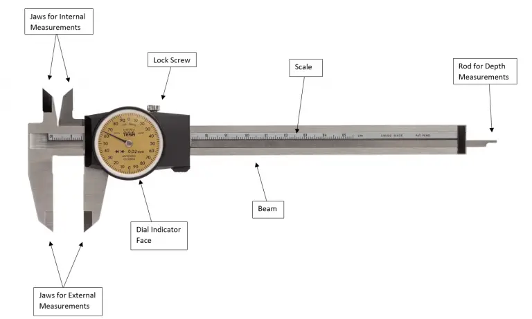
parts of a caliper

Make sure your tool is clean, especially the jaws of the caliper.

Slide the caliper closed.

For a digital caliper, hit the origin button – this will sometimes be labeled differently (such as Zero) based on the manufacturer of the caliper.

For a dial caliper, loosen the bezel lock screw, twist the dial until the needle reads zero and then lock the bezel lock screw again.

Once you have reset the zero location, make sure to verify it. Do this by opening the calipers up and then closing to the zero position again.

You want to verify that the caliper reads zero each time. The amount of pressure you put on the tool affects the measurement so make sure to use the same amount of force to close your caliper.

Consistent, gentle movements will help you get the most accurate readings out of your tool.

At this point you know your caliper is accurate at the zero location. What is not known is how that same caliper will measure at another location. It may be perfectly accurate at zero but off by ten thousandths or 0.010” at 6 inches.

This process is for your external jaws only and it is entirely possible that your jaws for measuring internal measurements such as holes may not be aligned with the external jaws. The zero location may be different for your internal and external jaws.

This is why ideally you would calibrate your calipers to verify their accuracy over the whole measuring range. Calibration requires additional equipment so many people won’t take the extra step.

What is important is to consider is what level of accuracy you need for your measurement.

Precision measuring tools = be gentle

These things are not hammers. You need to treat them gingerly. They won’t shatter into a million pieces when you set them on a bench but banging them or dropping them means you’re going to have a bad time.

The most common types of damage, all of which would affect accuracy are

  • Shock to the internal workings. This can cause excess drag in the mechanism or simply give bad measurements.
  • Damage to the jaws of the caliper such as nicks or burrs. Even a very small nick can cause your measurement to be off. The inside measurement jaws are more likely to be damaged than the outside measurement jaws.
  • The depth measuring rod can get bent or otherwise damaged and give bad readings. The rods tend to be long and thin which means it doesn’t take much force to damage them.

Calibration

gauge block set

Calibration involves taking a known length standard such as a set of gauge blocks and using them to check the accuracy of the caliper over its whole measuring range.

You would check the caliper at 0 inches, 6 inches and at random intervals between the two. This is the super simplified version of a calibration procedure. If you want a more detailed instruction, then check out our guide to caliper calibration.

Related articles