
Table of Contents
Toggle // is the GD&T symbol for parallelism. For the parallelism symbol, notice how the two lines of the symbol run together. They are parallel to each other.
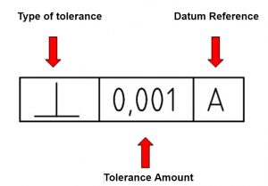
The blueprint item that contains the parallelism callout is called a feature control frame.
The components of a feature control frame are shown below.
The parallelism symbol would be inside the first box to indicate the type of tolerance.
The tolerance amount is listed in the middle box. This tolerance is in the the same units that the rest of your blueprint is in. Many times this will be listed in general tolerance block of the blueprint.
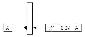
The datum reference is the feature that the feature with the parallelism callout will be compared to. In the example below, datum A is on the left and the right side has the parallelism callout attached to it.
This feature control frame reads “the right side of the part must be parallel within 0.02 to datum A”.
GD&T symbols are used to control the size, form and/or orientation of the different features on a part.
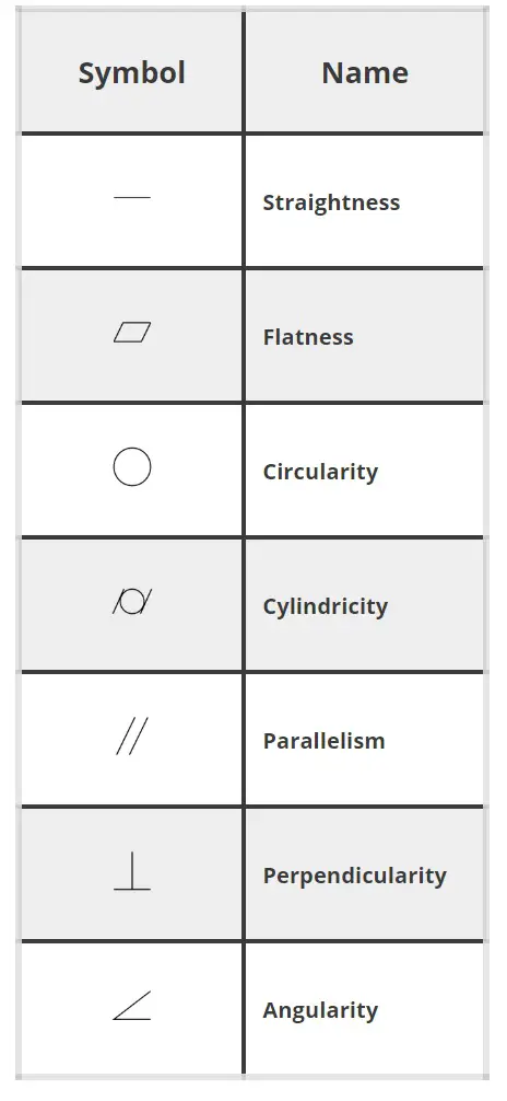
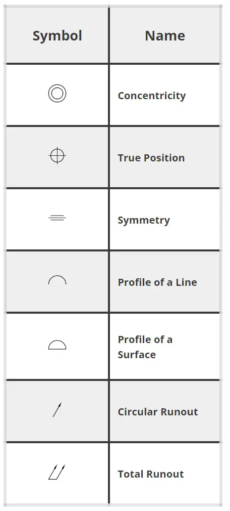
Check out the list below to learn about other GD&T symbols and if you want a more in depth guide that includes then check out our Complete Guide to Blueprint Symbols
GD&T is a complicated subject and understanding it correctly can be the difference between a perfect part and scrap.
The best way to learn GD&T is from experienced teachers who can break down the material into manageable pieces.
Luckily, we know someone.
And MachinistGuides.com readers get an exclusive discount on training!
Learn More Media LLC
5319 Hillside Way
Williamsburg, VA 23185
© 2026 Machinist Guides