Geometric dimensioning and tolerancing (GD&T) consists of a set of symbols and rules for applying them that communicates the requirements of an engineering blueprint.
GD&T controls variations of size, form, orientation, location and runout individually or in combination.
For help understanding even the most complex GD&T concepts, get comprehensive and practical training with an exclusive discount for MachinistGuides.com readers!
GD&T and Engineering Blueprint Symbols

True Position
Controls how far a feature can deviate from a given location.

Straightness
A tolerance given that defines how far from a perfect line a feature can be. A 2D (line) requirement.

Flatness
Similar to straightness but the callout applies over the entire surface (plane).
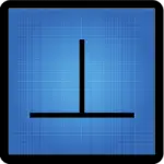
Perpendicularity
Defines the maximum allowed deviation of a feature from 90°.

Parallelism
Describes two features that are equally distanced from each other over their entire surfaces.

Angularity
Angularity is the allowed deviation from a theoretically perfect feature at a specified angle other than 90° or 180° from another feature.

Circular Runout
Controls the runout of a rotated circular at any single location on the feature.

Total Runout
Controls the runout of a rotated circular at all locations on the feature.

Profile of a Line
A tolerance that identifies how close to a specified design a feature is at specific cross section.

Profile of a Surface
A tolerance that identifies how close to a specified design a whole feature is.

Circularity
A tolerance that defines how round a feature must be at a single location.

Cylindricity
Similar to circularity but it applies over the entire cylinder instead of at a single point.

Concentricity
A requirement that the centerline or axis of two features are located within a specified tolerance of each other.

Symmetry
Controls the location of a feature such as a slot to a datum.

Envelope Requirement
Specifies that the feature may not exceed the minimum or maximum total size requirement. This applies at each cross section as well as over the entire feature.

Free State
For non-rigid parts, the specified GD&T requirements apply when the part is in a free state, where only the force of gravity is affecting the part.

Independency
Removes the form control for a feature. When independency is called out the feature size is controlled only by the attached requirement.

Least Material Condition (LMC)
A modifier that can give bonus tolerance based how close or far the features are from nominal size.

Maximum Material Condition (MMC)
A modifier that can give bonus tolerance based how close or far the features are from nominal size.

Projected Tolerance Zone
Used when a tolerance zone applies outside the boundaries of the physical part.

Regardless of Feature Size (RFS)
The tolerances do not change based on the size of the features. This is an older symbol that is no longer used. This condition is assumed unless specified otherwise now.

Tangent Plane
Creates a plane based on the highest contact points of a feature.

Unequally Disposed Profile
Profile tolerance zones are normally centered on the nominal dimensions. When this is not the case, the unequally disposed tolerance symbol is used to move the tolerance zone based off the nominal dimensions.

Continuous Feature
Identifies two or more separate features that should be treated as one such as two planes separated by a keyway.
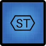
Statistical Tolerance
Specifies that statistical process controls can be used which may be more cost effective in some situations.

Slope
Identifies the rise over run of a feature. Shown as a ratio.

Conical Taper
The ratio of size difference between two diameter sections.

Datum Target Point
A single point that is to be used as a datum or as part of a datum.
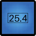
A basic dimension is a theoretically exact dimension used to calculate GD&T tolerances. Shown enclosed in a box. Older blueprints may identify the feature with BSC instead.
Reference dimensions are shown in parentheses. They are not blueprint requirements. They are shown for informational purposes only.

Arc Length
Describes the length along an arc. Measures the distance around the outside of the arc. It is not a chord length.

Dimension Not to Scale
Features are not shown with the same relative scale for all features.

Square
Identifies a feature that has equal sizes for both length and width.

Diameter
The distance across the center of a circle. Two times the radius.

Radius
Half of the diameter. The distance from the center of a circle to the edge.

Spherical Diameter
A sphere or ball shaped feature specified by the diameter of the sphere.

Spherical Radius
A sphere or ball shaped feature specified by the distance from the center of the sphere to the outside.

Controlled Radius
A radius without flats or reversals.

Common Tolerance Zone
Identifies two or more separate features that should be treated as one such as two planes separated by a keyway.

Datum
A feature which is used for location and measurement of other features.
A round, angled feature that allows a fastener such as a screw head to sit flush or below the surface.
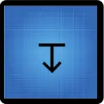
Depth of
Identifies how deep a feature is. Commonly applied to holes, counterbores, etc.

Surface Finish
Describes the surface texture or roughness of a surface. Can be specified as a max allowable roughness as shown above or a range.

Number of Places
An identifier that lists the number of instances of a repeated feature.

All Around
Identifies that a requirement applies around the entire perimeter (edge) of the part.

All Over
Identifies that a requirement applies to all surfaces and features of a part.

Datum Translation
Allows the identified datum locating feature to be adjusted so that the feature is fully engaged.
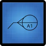
Movable Datum Target
Identifies datum targets that may be shifted in a specified direction.

Dynamic Profile Tolerance Zone
Controls the form of a feature. When the dynamic profile modifier is used, the profile callout does not control the size of the feature.
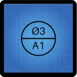
Datum Target
The top section is the size and shape of the target area. The lower section lists the identifying letter and number.
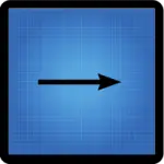
From-To
Indicates a gradual change in tolerance between two points. The arrow points in the direction of the tolerance change.

Between
Feature requirements apply between two specified locations.

Dimension Origin
Indicates the feature that another feature should be measured from. Often used to indicate a measurement should be taken from a shorter surface.
Frequently asked questions
What does GD&T stand for?
GD&T stands for geometric dimensioning and tolerancing.
What is GD&T used for?
GD&T is a way for engineers and designers to more accurately control features and tolerances on manufacturing drawings.
GD&T allows designers to place only the needed controls and tolerances on features which reduces cost and complexity of components.
GD&T is critical for designing mating parts and assemblies effectively.
What are the 5 categories of GD&T callouts?
The categories of GD&T symbols are form, profile, orientation, location and runout.
In addition there are a large amount of supplementary symbols which are used to identify blueprint requirements.
What standards control GD&T use?
There are two main standards which govern the use of various GD&T symbols.
ASME Y14.5 is the main standard referenced and the current revision is the 2018 version of the standard. The standard is commonly referred to as ASME Y14.5-2018 or on occasion simply, Y14.5-2018.
There are multiple ISO standards which govern the use of symbols and their interpretation. ISO 8015, ISO 1101 and ISO 2768 are the three most common standards that detail GD&T use and interpretation.
How to read a GD&T callout
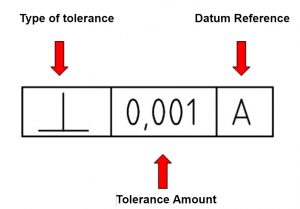
A GD&T callout comes in the form of a feature control frame.
Feature control frames are read from left to right.
It reads “Type of control” of “Tolerance” to Datum. It should be noted that if a diameter symbol is present before “Tolerance” then it indicates the shape of the tolerance zone is cylindrical.
Here are a couple examples with description of how to read them:

True position of 0.2 to datums A and B

Perpendicularity of 0.001 to datum A
What is the best way to learn GD&T?
GD&T is a complicated subject and understanding it correctly can be the difference between a perfect part and scrap.
The best way to learn GD&T is from experienced teachers who can break down the material into manageable pieces.
Luckily, we know someone.
And MachinistGuides.com readers get an exclusive discount on training!
