Table of Contents
ToggleHole types
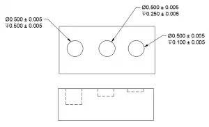
Blind holes are holes that get drilled or milled to a specified depth but do not go all the way through the part.
Thru holes
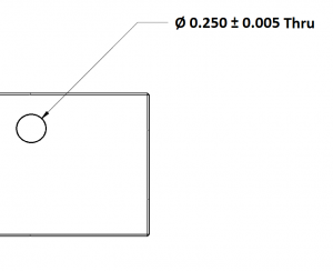
Thru holes get drilled all the way through a part.
They can be specified as “thru” as shown in the example or the blueprint can make it clear visually that the hole goes all the way through the part.
Blind holes vs thru holes
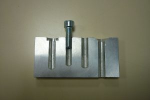
This picture of a part cut in half shows the difference between a thru hole and a blind hole. The three holes on the left are blind holes which do not break through to the other surface.
The thru hole on the right goes all the way through the part.
Symbols used to dimension holes

Diameter
The diameter of the hole is the size. The diameter is the distance across the hole.

Radii
Less often, holes are specified with a radial dimension instead of a diameter. The radius is the distance from the center of the hole to the edge of the hole. This is equal to 1/2 of the diameter.

Depth
The depth of the hole is the distance that it is drilled to.
Features associated with holes
Holes often get counterbores that allow a fastener such as a bolt head to be recessed.
Holes with a counterbore will specify the size and depth of the hole as well as the size and depth of the counterbore.
Countersinks get added to holes as either a way to specify a chamfer for protective purposes or to allow a fastener such as a screw head to be recessed.
Holes with a countersink will specify the size and depth of the hole as well as the size and angle of the countersink.
Spotfaces are functionally no different than a counterbore. They are machined on a part to allow a fastener to sit flush, though not always completely recessed.
Holes with a spotface will specify the size and depth of the holes as well as the size and depth of the spotface.
Note: spotfaces are not always specified with the symbol shown. At times, they will only use the counterbore symbol and other times they will use the SF notation only.
Want to learn more?
GD&T is a complicated subject and understanding it correctly can be the difference between a perfect part and scrap.
The best way to learn GD&T is from experienced teachers who can break down the material into manageable pieces.
Luckily, we know someone.
And MachinistGuides.com readers get an exclusive discount on training!
