Table of Contents
ToggleCommon Blueprint Symbols

Nominal Size
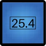
In the example shown, 24 is the nominal size. It is the size that the tolerance envelope is based on. A reference/starting point.
Plus or Minus
Plus or minus is the most common tolerance type. They are less common, but tolerances can be all negative, all positive or +/- with enequal sizes such as +3/-2.

Degree Symbol
The symbol used to callout angle requirements.
Reference dimensions are shown in parentheses. They are provided for informational use only. They are not size requirements but often help make the print easier to understand.
Symbols For Features

Radii
Half of a circle. The distance from the center of a circle to the edge.

Diameters
The distance all the way across a circle. Two times the radius. This symbol gets used with other symbols as well such as counterbores, countersinks, and true position callouts.
Depth of
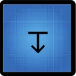
This symbol specifies the depth of a feature.
A counterbore is a flat bottomed, recessed hole.
Countersinks are a round, angled feature added to a hole. They are often used to allow a screw head or other fastener to sit flush with the surface.

Surface Texture
A symbol for defining the surface finish of a part. There are many variations of the surface texture symbol but most often it is used with a microinch or micrometer value callout that specifies the roughness of a surface.
Symbols Used In GD&T Callouts
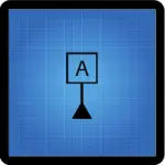
Basic dimensions represent a theoretically perfect feature or size. They are shown enclosed in a box and are the basis for many GD&T callouts.
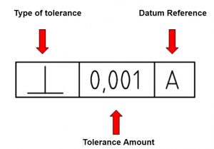
Feature control frames contain a geometric dimensioning and tolerance callout.
The example shown reads, the feature is perpendicular to within 0.001 to datum A.
GD&T Symbols
Symbols For Roundness

Circularity
Otherwise known as roundness. Circularity only applies at one location. You might check the roundness of a hole at a specific depth.

Cylindricity
Cylindricity is roundness but over all locations of a feature. Cylindricity of a hole would mean the hole must be round at all points.
Symbols Used for Flat Things
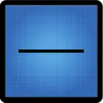
Straightness
A straightforward requirement. The feature must be a straight line within the specified tolerance.

Flatness
Similar to straightness but over a whole surface. The high and low of a surface must be within the specified tolerance of each other.
Symbols Used to Control Angles
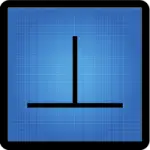
Perpendicularity
Two features must be 90 degrees to each other.

Parallelism
Two features must run together (180 degrees to each other).
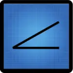
Angularity
Angularity is used when two features must be have a specific angle between them and the angle between the features is not 90 or 180 degrees.
Symbols Used for Profile

Profile of a Line
Profile of a line controls the shape of a feature. Imagine it as controlling the outline of a feature.

Profile of a Surface
Profile of a surface controls the shape of a feature but instead of controlling it in one location like profile of a line, it applies to the entire feature surface.
GD&T Symbols That Control Location of a Feature

True Position
Controls location of a feature based on the variation from the basic dimensions.

Concentricity
A requirement that the centerline or axis of two features are located together.

Symmetry
A requirement that a feature must be evenly located based on another feature. Centered based on a feature or location.

Circular Runout
Controls how even a surface is when spun in a circle.

Total Runout
The same as circular runout but at all locations on the feature. Circular runout and total runout have a relationship similar to circularity and cylindricity.
Symbols That Change Tolerance

Maximum Material Condition
A modifier that can give bonus tolerance based how close or far the features are from nominal size.

Least Material Condition
A modifier that can give bonus tolerance based how close or far the features are from nominal size.

Projected Tolerance Zone
Used when a tolerance zone applies outside the boundaries of the physical part.

Regardless of Feature Size
The tolerances do not change based on the size of the features. This is the default spec and any tolerance is assumed to be regardless of feature size even if the symbol is not used.

Unequally Disposed Tolerance Zone
Profile tolerance zones are normally centered on the nominal dimensions. When this is not the case, the unequally disposed tolerance symbol is used to move the tolerance zone based off the nominal dimensions.
Want to learn more?
GD&T is a complicated subject and understanding it correctly can be the difference between a perfect part and scrap.
The best way to learn GD&T is from experienced teachers who can break down the material into manageable pieces.
Luckily, we know someone.
And MachinistGuides.com readers get an exclusive discount on training!
