Beginner’s Guide to Micrometers – Get Started

a 0-1" outside micrometer
A standard outside measuring micrometer

What is a micrometer?

A micrometer is a precision measuring tool. 

They are used in manufacturing, machine shops, automotive work and the construction industry. 

“Mic” is shorthand for micrometer.

Mics are very accurate measuring devices. 

Micrometers are used to take measurements with an accuracy of ~.0001″ or better in inches. 

Measurements in millimeters can be made down to .01mm or .001mm.


How accurate are micrometers?

Most micrometers have an accuracy of +/- 0.0001″, commonly referred to as a tenth of an inch in machining.

The standard metric versions would come as +/- 0.001mm or +/- 0.002mm.

They can be found with worse or better accuracy but what is usually seen .

When to use a micrometer

Three of the most common precision measuring devices used by a hobbyist or a machine shop are calipers, micrometers and dial test indicators. 

Calipers have the least accuracy of the three and the largest measuring range.

a mitutoyo digital caliper with the display on
Mitutoyo digital caliper

The dial test indicator has the most accuracy and least measuring range. 

Micrometers are in the middle for both accuracy and measuring range. 

While still very accurate, one downfall of the micrometer is that they usually come with a 1″ measuring range (3-4″, 4-5″, etc.).

Because of this they are often sold in sets to cover a larger measuring range. 

A 0-6″ micrometer set will cover the needs of most applications while a 0-12″ set is more than most people, especially hobbyists will need. 0-3″ sets are also common.

Parts of a micrometer

a micrometer with all of its part identified

How to use a micrometer

Before using your micrometer, ensure that the measuring tool and surface to be measured are free of dirt, debris, chips, etc.

Everything should be clean.

The micrometer thimble should spin freely. No hangs up or anything similar.

a micrometer with the thimble identified

Open the thimble to place the part you want to measure between the anvil and spindle.

Spin the thimble until it closes on the part. 

You aren’t trying to clamp down on the part. 

closeup of a micrometer with the ratchet stop identified

Use a gentle, consistent amount of force when spinning the thimble. Using the ratchet on your micrometer can make this easier. Try spinning the thimble until you get three clicks on your ratchet.

This will help you get repeatable measurements. You want to be consistent in your measuring so you know your readings are good.

This is why taking multiple measurements is so important.

When possible, measure the part multiple times to be confident your readings are accurate.

A little practice on a cheap gauge block can help here. Measure that same gauge block a bunch of times and you will become more repeatable in your measurements. You’ll also see how easy it is to change your reading.

a micrometer with the anvil and spindle identified

As the spindle closes on the part being measured, it can be beneficial to slightly rock the micrometer in an effort to seat the micrometer on the part.

Be careful: this technique isn’t right for surfaces that could be scratched or damaged easily.

Once you have closed the part in the micrometer, it is time to take your measurement reading.

How to read a micrometer

The most common variety of micrometers measures to one ten-thousandth of an inch (.0001″).

Measurements are taken by identifying where the lines on the micrometer line up.

You will need to take 4 readings and add them together to get your measurement.

These readings are the 0.1000″, 0.0250″, 0.0010″ and 0.0001″ readings.

Machinists refer to these as the hundred thousandths, 25 thousandths, 1 thousandths and lastly the tenths readings.

Let’s get started.

Along the sleeve of the micrometer will be graduations similar to a ruler. The graduations at every fourth interval are most often numbered 0, 1, 2 and so on. 

These numbers represent .100″ or one hundred thousandths of an inch. 

closeup of a micrometer with the 0.100" graduations identified

Whichever hundred thousandths reading you are past is your reading. In the pic above, the hundred thousandths reading would be 3 which equals 0.3000″.

Once you have taken your hundred thousandths reading then you will need to take the 25 thousandths reading.

Each mark along the sleeve is 0.025″ or 25 thousandths.

closeup of a micrometer with the 0.0250" graduations identified

Next is the reading from the thimble. This is the 0.0010″ reading or one thousandth of an inch reading. 

In the pic above two lines are shown past the three so the 0.0250″ graduation value would be 0.0500″.

In the end we are going to add all of our individual measurements up for our final reading.

closeup of a micrometer with the 0.0010" graduations identified

Note the 0.0010″ reading on the thimble and lastly take the tenths reading from the spindle.

Here we have 15 thousandths.

This makes our measurement so far 0.300″ + 0.0500″ + 0.015″ = 0.3650″.

closeup of a micrometer with the 0.0001" graduations identified

The last reading to take is the tenths reading. If the lines matched up at the 6 tenths mark, then we would have a reading of 0.0006″ which we need to add to our previous readings.

0.3650″ + 0.0006″ = 0.3656″ or three hundred and sixty five thousandths of an inch and six tenths.

Frequently asked questions about micrometers

What kinds of micrometers are available?

There are a ton of different micrometer types available

Often specific industries have their own special type micrometers such as the auto related micrometers on our list of the most common micrometers below:

  • Outside micrometers – measures various lengths, widths, thicknesses and diameters
  • Inside micrometers – measures hole diameters, slot widths
  • Depth micrometer – measures depth of holes, step locations
  • Thread micrometers – measures various thread characteristics
  • Crankshaft micrometer – specific measuring range for measuring crankshafts
  • Disc brake micrometer – measures thickness of brake rotors
  • Blade micrometer – measures slots, keyways and grooves

Are cheaper micrometers as good as expensive ones?

The cheaper off-brand micrometers have gotten much better in recent year, but they haven’t quite caught up to the best manufacturers yet. 

Starrett and Mitutoyo still reign supreme in terms of quality and accuracy.

You can always look for used options on Craigslist or Facebook marketplace to save a buck.

What makes a good micrometer?

A good micrometer needs two things: precision and accuracy. 

Some adjustments can be made with most micrometers to account for small errors in accuracy but nothing can be done to fix a tool that isn’t precise. 

Quality micrometers will turn smoothly without any drag. This is the telltale sign of a good tool. If your micrometer ever feels like it is rubbing internally, we recommend disassembling the micrometer and cleaning per the manufacturers instructions to eliminate any possible contamination that may be causing the issue

How to adjust a micrometer

If your micrometer is in need of adjustment, most micrometers can be adjusted by using the wrench that came with your tool to spin the sleeve of the micrometer. This is usually done in the zero position. This can be especially useful for adjusting for the touch or feel of a mic when it does not include a ratchet or friction stop. 

If you no longer have a wrench or spanner for adjustment, replacement wrenches can be purchased from most manufacturers or on Amazon.

How often should my micrometer be calibrated?

How often you need to calibrate your micrometer will vary depending on a few factors such as what you are measuring with it, how often you are using it, and what type of environment it is in.

Check out our guide to micrometer calibration to get a better understanding of the how, where, when and why of calibrating your mics.

Beginner’s Guide To Reading Machine Shop Numbers & Values

math on chalkboard

Confused? If you’re reading this page then I’m pretty sure you are. Dealing with numbers, values and calculations when machining or 3d printing can be hard for those just starting. 

The lingo and terminology used by many people both online or at a new job can be hard to understand. My hope is that after this quick lesson in dealing with machine shop numbers, you will not only be comfortable reading your numbers and measurements but also will know how to perform some simple calculations using them. 

Let's begin

First we need to understand what the numbers we are working with represent.

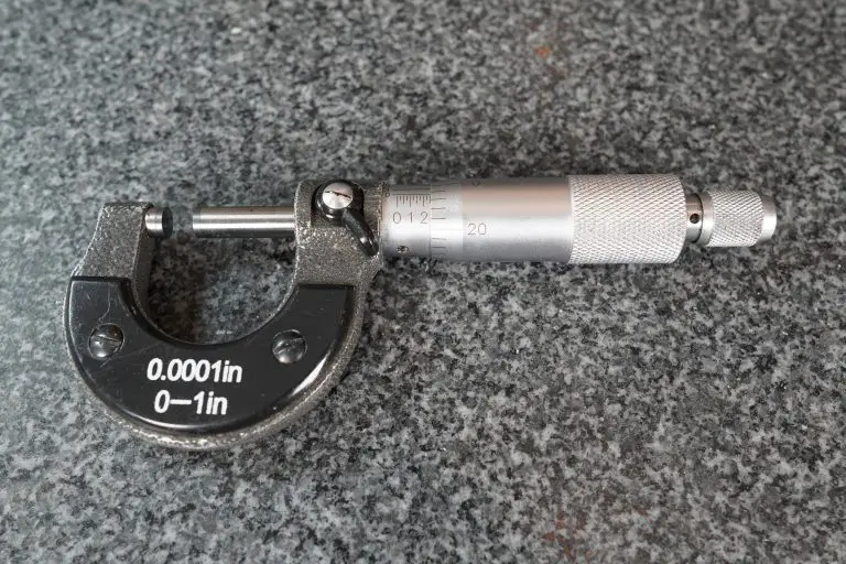
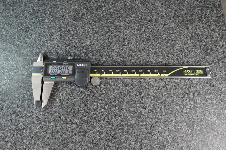
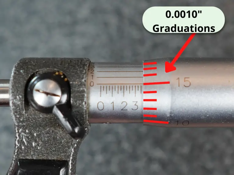
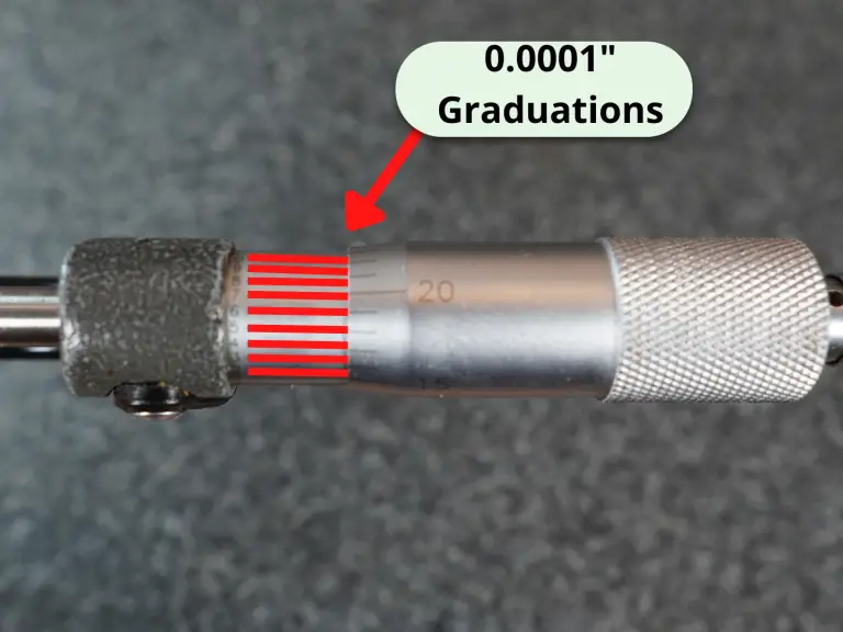
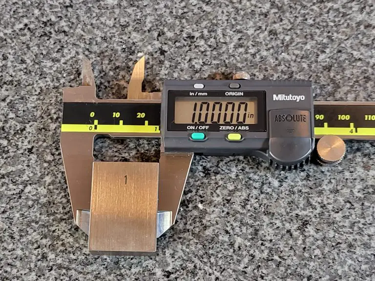
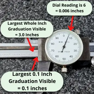
Whether they are a reading on a micrometer, a spec on a blueprint or a stack of gage blocks, the goal is the same.

We need to know how to read them and work with them. 

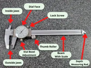
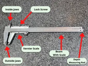
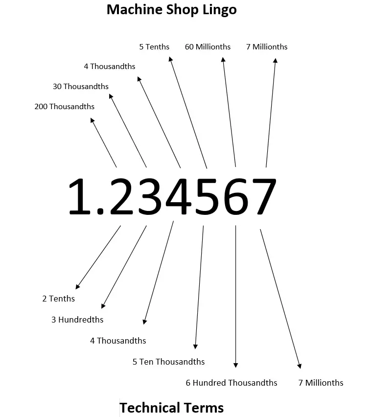
Below is a graphic that shows the name (including machine shop lingo) for different values.

Pay attention to how far each number is from the decimal place when looking at the chart.

Please note that not everyone will be working down to millionths of an inch but I included them for reference. Many will only work down to the the values shown in this table. 

Value

Machinist Lingo

Technical Math Term

0.001"

Thousandth or Thou

Thousandth of an Inch

0.0001"

Tenth

Ten Thousandth of an Inch

Keep in mind that all these numbers and terms apply to imperial units (inches).

How to say the value

Machine shops usually speak in terms of thousandths of an inch. Because of this when we describe the value to someone else we will read it a little different than you might expect.

As noted above, if we give the example of 7.489136″ a machinist would describe the value as 7 inch, 489 thousandths, 1 tenth, 36 millionths. 

Read that last sentence over a couple times to really understand the terms your typical machine shop speaks in.

As a note, not all machine shops or hobbyists will deal in millionths of an inch and some might not even work with tenths but I have included them for reference.

Note: Thousandths of an inch is often abbreviated as “thou” especially when discussing values verbally. 

Machine shop number reading examples

Below are some more examples to show how machinists communicate values:

Value

Machinist Lingo

1.325"

1 inch 325 thousandths

0.5001"

500 thousandths 1 tenth

0.021

21 thousandths

0.6532"

653 thousandths 2 tenths

9.792345"

9 inch 792 thousandths 3 tenths 45 millionths

Gage blocks

A common scenario for someone new in a machine shop is learning how to set up a stack of gage blocks.

I’m not going to show you how to pick the right gage blocks for your stack here. If you need those instructions then head over to Starrett’s website. They have great instructions that show you how to select your gage blocks and make a stack of a specific height. 

The link also contains information related to the use and care of your gage blocks. Take care of your gage blocks people, those things are expensive.

How to setup calculations

Now I said I would show you how to work with these numbers, so let’s demonstrate how to do that.


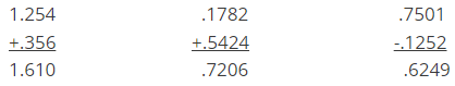
The important part when dealing with numbers or values in a machine shop context is to line up the decimal point. Below you will see some examples of addition and subtraction of numbers:

Simple calculation examples

addition and subtraction of values

For practice, let’s list out how to say those answers!

Value

Machinist Lingo

1.610"

1 inch 610 thousandths

0.7206"

720 thousandths 6 tenths

0.6249"

624 thousandths 9 tenths

texas instruments ti-30xa calculator

There aren’t any other special tricks here. Once you line up the decimal places everything else is just like you learned early in school. Also consider yourself lucky we have calculators.

That’s it. Now you should know how to speak in terms that a machinist would understand and use the values in simple calculations. 

If you need more in depth training when it comes to machine shop math, check out the training linked below. It breaks all the hard subjects down into bite sized pieces to make them easy to understand.

Beginner’s Guide to Basic Dimensions

Basic dimensions are shown on a blueprint enclosed in a box. But what do they mean?

Keep reading to find out.

What is a basic dimension?

A basic dimension is a theoretically exact size or location.

Basic dimensions do not have a tolerance applied to them, this includes any general tolerance blocks.

Instead a separate is listed on the drawing that uses the basic dimension.

An example of this would be a true position callout for a hole or set of holes. The basic dimension(s) specify the location of the hole.

The true position of the hole is calculated based on the difference of the actual location compared to the basic dimensions theoretically exact location.

What is a basic dimension used for?

Basic dimensions are used for calculations. They are used to calculate various geometric dimensioning and tolerancing (GD&T) characteristics such as true position, profile or angularity.

In the example above, the 120 degree callout and the 42 diameter bolt circle are the basic dimensions and the true position of 0.2 is the characteristic controlling the basic dimensions.

Using basic dimensions

How is a basic dimension shown on a drawing?

basic dimension example

The symbol for a basic dimension is the dimension shown enclosed in a rectangular frame or box.

This is the convention identified in the blueprint drawing standard ASME Y14.5.

Some drawings may list a basic dimension not in a rectangular frame but instead the dimension will be followed by a Bsc. notation. This is more common on older drawings and does not change the way basic dimensions are used.

Basic dimension examples

basic dimensions for a bolt hole circle
This example has 2 basic dimensions. Both the size of the bolt hole circle and the angle between the holes are basic dimension.

Basic dimensions and tolerances

Can a basic dimension have a tolerance?

A basic dimension itself does not have a tolerance. General tolerance blocks do not apply to a basic dimension.

Instead its value is used to compute another characteristic such as angularity, profile or true position.

general tolerance block
An example of a general tolerance block

Basic dimensions compared to other types of dimensions

Basic dimension vs reference dimension

Basic dimensions are associated with another tolerance or dimension. While they don’t have a tolerance tied to themselves, they are used to calculate another toleranced feature such as the true position of a hole.

Reference dimensions are simply placed on a drawing or blueprint for reference. They have no tolerance associated with them. No matter how far off the given value a reference dimension is, it would never be cause for rejection.

A basic dimension being far off its nominal value would not be cause for rejection itself, but its effect on another feature referencing the basic dimension could be cause for rejection. So if a basic dimension was far off the nominal location, another tolerance would likely be out of spec. 

reference dimensions

Basic dimension vs regular dimension

Regular dimensions have a tolerance assigned to them. This can be directly assigned to the individual dimension or it can be the general tolerances. The regular dimension must fall within the limits of the tolerance.

A basic dimension is instead controlled by another characteristic. The basic dimension can vary by any amount but it must not deviate from the nominal value to the point that the other characteristic (true position callout, profile callout, etc.) is no longer within the specified limits.

How to measure a basic dimension

A basic dimension is measured just like any other dimension. The only difference is that the basic dimension doesn’t have a tolerance directly associated with it. Instead another dimension uses the basic dimension to calculate its value.

How to report basic dimensions

Do basic dimensions need to be listed on an inspection report?

While there isn’t a strict requirement anywhere to include them, I would recommend reporting their values on an inspection report. 

The features have been measured and you likely already have the values. By recording them, you will provide more information and value for your customer. 

You must report the feature control values such as true position, profile value, etc. that use the basic dimension to be calculated.

What about on FAIs?

The requirement for reporting basic dimensions is the same for first article inspection reports. Be aware that some customers may require them even though there is no requirement per AS9102.

Want to learn more?

GD&T is a complicated subject and understanding it correctly can be the difference between a perfect part and scrap.

The best way to learn GD&T is from experienced teachers who can break down the material into manageable pieces.

Luckily, we know someone.

And MachinistGuides.com readers get an exclusive discount on training!

Break Edge – All About

What is a break edge?

break edge blueprint examples

A break edge means the removal of material, usually in the form of a chamfer or radius to remove the sharp edge.

Machining a surface will often leave a corner which can be dangerous for both the part and the part handler. Many times there will be a burr (raised piece of material), left on the edge which can be razor sharp. Using a deburring tool can break the edge to remove the sharp 

A broken edge is usually specified as a maximum value or with no value at all. If no value is specified, the break edge has not been constrained sufficiently.

A break edge callout with no maximum size referenced would normally be assumed to be approximately .005-.010” though in some instances it could be larger.

What does a break edge look like?

Break edge on a physical part

In the brass cube below, notice how the corners have all the sharp edges removed. This is an example of a break edge.

metal cube with break edge

Break edge on a blueprint

Break edge symbol

There is no GD&T symbol for a break edge. Break edges are also not referenced in the engineering drawing standard ASME Y14.5.

Break edge callouts are specified directly on the drawing to reference a certain surface or as a note e.g. “Break all sharp edges”.

At times, the break edge specification may be contained in the general tolerance block such as shown below.

Break edge note example

general break edge note on blueprint
Break edge note example

How to make a break edge

Break edge on wood

Using 180 grit fine sandpaper is the easiest way to create a break edge on a wooden workpiece. This can also be used together with a block plane to chamfer the edge and then soften it with a light sanding.

Break edge on metal

Because metal tends to be more durable, you have more choices for creating a break edge on your piece of metal.

You can use:

  • A chamfer deburring tool which is a specialty tool designed to remove burrs from the edges of parts
  • A file to knock the edge off a part
  • Sandpaper
  • A grinding wheel
  • A rotary tool such as a Dremel

Break edge on glass

To create a break edge on a piece of glass, use one of the following:

  • Diamond file
  • Grinding wheel
  • Rotary tool with diamond wheel

How to measure a break edge

Which measuring tools to use

igaging pocket comparator with reticles and case
A pocket comparator with various reticles for measuring

The size of a break edge is measured the same as a standard chamfer or radius. If a measurement is required, a pocket comparator or eye loupe with a reticle are the most common inspection tools to use. 

An optical comparator with or without an overlay could also be used. See the examples below to better understand how the size of a break edge would be determined.

How to measure the break edge based on your blueprint

break edge examples

On the left is a chamfered break edge. The size is measured from the left edge of the part to the intersection of the break edge and the top of the part. This is done in both the x and y directions (up and down, left and right). 

On the right is a break edge created by a radius. The same measurement technique applies with the exception that the intersection would now be called the tangent point or point where the radius meets the straight edge.

Break edge compared to similar features

Break edge vs chamfer

The difference between a break edge dimension and a chamfer dimension is generally in the tolerancing of the two. A chamfer is usually thought of as being toleranced in a way that places tighter constraints on the feature. 

Often a chamfer callout will have a tolerance associated with the angle and a break edge will not.

Break edge vs radius

A break edge can be a radius. Many times, the person or company machining the part will round the edge using a variety of techniques including tumbling, specialty tools or even sandpaper.

Want to learn more?

GD&T is a complicated subject and understanding it correctly can be the difference between a perfect part and scrap.

The best way to learn GD&T is from experienced teachers who can break down the material into manageable pieces.

Luckily, we know someone.

And MachinistGuides.com readers get an exclusive discount on training!

Reference Dimensions [Guidance and Examples]

What is a reference dimension?

single reference dimension

A reference dimension is just what it sounds like. It is a dimension shown for reference. In other words it is there for informational purposes only.

They are not a requirement in any way.

Reference dimensions can be used to clarify other dimensions on a drawing. In some instances, they make a drawing easier to understand.

Reference dimensions on blueprints

How are reference dimensions shown on a drawing?

There is no GD&T symbol for a reference dimension. Reference dimensions are shown on a drawing as a value enclosed in parentheses.

An alternate method is to follow the dimension with “Reference” or “Ref”. The use of “Ref” or enclosing the dimension inside parentheses are by far the most common notations used. These notations are specified in ASME Y14.5 the Dimensioning and Tolerancing standard.

When to use a reference dimension

Reference dimensions are useful for clarification purposes. Their inclusion can make it clear how another dimension should be inspected or manufactured.

At other times they are included to make the drawing easier to read. It isn’t always immediately clear what a part looks like by looking at the blueprint.

A very common use of reference dimensions is to provide a conversion of the length units of the drawing from either metric to inches or vice versa.

Watch out for these conversions! Too often they are rounded excessively and not accurate. Reference dimensions should never be used for acceptance..

Reference dimension examples

reference dimensions

These examples show some of the variety you might see on your blueprints to call out reference dimensions.

Reference dimension measurement

Do reference dimensions have tolerances?

Reference dimensions do not have tolerances. Additionally, the general tolerances you find in a tolerance block do not apply to them.

Are reference dimensions measured?

Reference dimensions can be measured and the results recorded but this is not a requirement. Often reference dimensions will be recorded more as a note.

Reference dimension vs basic dimension

Reference Dimensions

Basic Dimensions

Shown in parentheses or with Ref notation

Shown enclosed in a box

Informational only

Controlled by another tolerance (GD&T)

Do not need to be measured or recorded

Will need to be measured for calculation

Basic dimensions are used in GD&T tolerancing. associated with another tolerance or dimension.

While they don’t have a tolerance tied to themselves, they are used to calculate the tolerance of another feature such as the true position of a hole. If the location of a hole was controlled by basic dimensions, you would never reject it for the hole location but instead for violating a GD&T requirement such as true position.

In other words, basic dimensions don’t have their own +/- tolerance but they are controlled by a different tolerance requirement.

single reference dimension
An example of a reference dimension
basic dimension example
An example of a basic dimension

Reference dimensions do not have a +/- tolerance and are not controlled by another requirement. They have no tolerance associated with them. No matter how far off the given value a reference dimension is, it would never be cause for rejection.

A basic dimension being far off its nominal value would not be cause for rejection itself, but its effect on another feature referencing the basic dimension could be cause for rejection.

Basic dimensions are identified with a rectangular frame around them such as in the example below.

Want to learn more?

GD&T is a complicated subject and understanding it correctly can be the difference between a perfect part and scrap.

The best way to learn GD&T is from experienced teachers who can break down the material into manageable pieces.

Luckily, we know someone.

And MachinistGuides.com readers get an exclusive discount on training!

Ballooning/Numbering A Blueprint

What is a ballooned or numbered blueprint?

ballooned drawing example

Commonly referred to by many different names including ballooned drawing, bubble drawing, numbered print, etc. A numbered drawing or blueprint is a way to identify individual attributes of a part or assembly as depicted in an engineering drawing. The numbers and balloons or bubbles are ordinarily done in red ink or a red font as seen above.

What are ballooned drawings used for?

Numbered drawings are a common component in the inspection process. They can be a part of your in house inspection procedure or a requirement which you provide to your customers. Ballooned drawings are also frequently used as part of a first article inspection report package. They allow the reader to connect an individual measurement to its location on the blueprint. This is especially handy when multiple attributes with the same nominal values are present.

How to number a drawing

Numbering or ballooning a blueprint is a process that has some flexibility to the order in which attributes are labeled. The most important aspect is that all attributes are assigned a number including all notes and general tolerances as needed. When in doubt, number it. Where to start is a matter of preference but make sure that your numbering sequence is easy to follow. Generally the person numbering the drawing will start in the top left view and work their way clockwise assigning numbers to attributes in that particular view. This process is repeated for all views present on the drawing in a top to bottom, left to right manner similar to the way you read a book. Some users will list attributes in the notes first such as material, but this is simply a matter of preference. Just make sure to number all the relevant attributes in the notes. If you work in a logical manner, it will be much easier for the customer or reader to follow along.

Example of a fully numbered drawing

What to include in a numbered drawing

Assign a number to every attribute on the print including all notes and applicable general tolerances. Some notes may include more than one attribute in a single note which requires a numbered attribute.

Related Articles

Feature Control Frames – All About

What is a feature control frame?

A key component of geometric dimensioning and tolerancing (commonly referred to as GD&T). On engineering blueprints, the feature control frame consists of a symbol to identify the type of tolerance, the amount of tolerance and reference datums if applicable.

How to read a feature control frame

A feature control frame is read from left to right. It reads “Type of control” of “Tolerance” to Datum. It should be noted that if a diameter symbol is present before “Tolerance” then it indicates the shape of the tolerance zone is cylindrical.

Examples

true position callout

True position of 0.2 to datums A and B

perpendicularity callout example with feature control frame

Perpendicularity of 0.001 to datum A

cylindricity callout

Cylindricity of 0.001

circular runout callout

Circular runout of 0.010 to datum A

Composite feature control frame

A composite feature control frame controls both a pattern on a part and the location of individual items in the pattern. 

The upper section of a composite feature control frame specifies the tolerance for the pattern to the overall part. 

The lower section specifies the tolerance for individual features to the pattern. In the example of a bolt hole circle, the upper section controls the tolerance for the location of the bolt hole circle on the part. The lower section would control how closely the individual holes must follow the pattern.

composite feature control frame

Feature control frame symbols

gd&t symbols
gd&t symbols

For more information see our GD&T Symbols Quick Reference

Basic dimensions

Basic Dimension Blueprint GD&T Symbol dimension in a box

Basic dimensions are identified by a rectangular frame around the dimension. 

They are dimensions that are theoretically exact. They do not have a tolerance themselves (general blueprint tolerances do not apply). 

Instead they are controlled by another characteristic. This is often seen with positional tolerances such as the true position of a hole. The hole location will be specified as basic dimensions. 

A true position tolerance will then be assigned to the hole which will control how far off the nominal location the hole can be.

Want to learn more?

GD&T is a complicated subject and understanding it correctly can be the difference between a perfect part and scrap.

The best way to learn GD&T is from experienced teachers who can break down the material into manageable pieces.

Luckily, we know someone.

And MachinistGuides.com readers get an exclusive discount on training!

Related Articles

A Beginner’s Guide to Depth Micrometers

mitutoyo depth micrometer

What is a depth micrometer?

A depth micrometer (or depth mic) is a measuring tool commonly used to check precise measurements of slots, keyways, grooves and various other locations. They are a very accurate measuring device. 

Depth micrometers are commonly used to take measurements to an accuracy of .001″ or .0001″ in inches. Measurements in millimeters can be made down to .01mm or .001mm.

How to use a depth micrometer

Depth mics can be used to measure many different types of part characteristics. I will explain how to check a hole depth. 

Before using your micrometer, ensure that the measuring tool and surface to be measured are free of dirt, debris, chips, etc. The micrometer thimble should spin freely.  Place the tool on part over the hole. Spin the micrometer thimble until the rod extends to the bottom of the hole. Use the ratchet or friction stop if available on your tool.

depth micrometer rod
A depth micrometer rod

Note: The depth mic should be checked for accuracy whenever a rod is changed to measure a different size. It can be easy for something to get contamination in between the micrometer and the depth rod where they come together. 

Keeping things as clean as possible will help with this problem.

How to read a depth micrometer

I recommend a digital depth micrometer for ease of measurement especially if the measurer will only occasionally be taking readings with their micrometer. Unfortunately the price of a digital depth mic can be quite high so if you must use an analog micrometer then please keep reading. 

The most common varieties of depth micrometers read in increments of one thousandth of an inch (.001″) or one ten-thousandth of an inch (.0001″). The process of reading a measurement from either type is similar. Along the sleeve of the depth micrometer will be graduations similar to a ruler. 

The graduations at every fourth interval are most often numbered 0, 1, 2 and so forth. These numbers represent .100″ or one hundred thousandths of an inch. If using a depth micrometer with a 1-2″ rod, the graduation marked 6 would correspond to a measurement of 1.600″. The graduations between the numbers are each .025″ or twenty five thousandths of an inch. If we were to use a depth micrometer with a 4-5″ rod and obtained a measurement at the 3rd graduation after the .200″ mark, then our reading would be 4.275″. This would be the reading if the 0 on the thimble lined up exactly with the 3rd graduation after the .200 mark on the reading line. 

If instead the number ten lined up with the reading line and we could still see the 3rd graduation after the .200″ mark, then our measurement would be 4.285″. For micrometers that read to .0001″ we would additionally rotate the micrometer without turning the spindle to determine which numbers line up on the sleeve and thimble. If a number lines up on the thimble with the number 7 on the sleeve, our reading would now be 4.2857″.

Formula for depth micrometer readings

Base depth micrometer rod size + (.100″ x largest visible number) + (.025″ x graduations visible after the largest number) + (.001″ x reading from thimble) +(.0001″ x reading from sleeve for .0001″ micrometers)

Example for a depth micrometer with a 1-2″ rod

1.000″ + (.100″ x 4) + (.025″ x 2) + (.001″ x 3) + (.0001″ x 8) =

1.000″+ .400″ + .050″ + .003″ + .0008″ = 1.4538″

When to use a depth micrometer

Depth micrometers while very accurate have one downfall. Depth micrometers like most standard micrometers are most commonly found in 1″ measuring range increments (3-4″, 4-5″, etc.). For a depth micrometer, this means that multiple sized rods are needed to be capable of covering the measurer’s  measurement needs. Because of this depth micrometers are commonly sold in sets. 

A 0-3″ micrometer set will cover the needs of most applications while a 0-12″ set is more than most people, especially hobbyists will need.

What makes a good depth micrometer

A good depth micrometer needs two things: precision and accuracy. Some adjustments can be made with most depth micrometers to account for small errors in accuracy but nothing can be done to fix a tool that isn’t precise. 

Quality depth micrometers will turn smoothly without any drag. This is the telltale sign of a good tool. If your depth micrometer ever feels like it is rubbing internally, disassemble the micrometer and clean per the manufacturers instructions to eliminate any possible contamination that may be causing the issue.

Where to buy depth micrometers

Depth micrometers are available from a number of online retailers. For a more in depth guide of which depth micrometer is best for your situation, please see our reviews section

Some general advice, as usual for most products Amazon has a number of good options available. Walmart sells depth micrometers but we do not recommend any that they currently offer.

Are cheaper depth micrometers as good as expensive ones?

While some of the cheaper (made in China) type depth micrometers have gotten much better than they were in years past, they are nowhere near the same quality that you will see in a depth micrometer from one of the tried and true manufacturers such as Starrett or Mitutoyo. 

A depth micrometer is the type of tool that is best to purchase once. In most cases it can be more beneficial to search for a used option on Craigslist or Facebook marketplace. Ebay can also be a good alternative. For more information on the best depth micrometers for your application, see our Best Depth Micrometers article.

How to calibrate a 0-1" depth micrometer

  1. Verify that the micrometer is clean.
  2. Visually examine the micrometer for any condition that could cause errors in the calibration.
  3. Whenever necessary to disassemble for adjustment, use care and cleanliness to assure no damage to the internal threads of the tool.
  4. Spin the thimble until the depth rod is inside the tool.
  5. Place the tool on a surface plate and spin the thimble to extend the depth rod to the zero position. Use the ratchet or friction stop if available.
  6. Repeat the process by placing the depth micrometer on gage blocks and overhanging the tool to allow the depth rod to extend down to the surface plate.
  7. Check accuracy of the micrometer at various locations within the tool’s measuring range. Gage blocks which have been calibrated themselves should be use for this operation. Block sizes which are used should test the micrometer at different positions of the thimble and not only increments of .025″. This ensures the scale on the thimble is accurate.
  8. Adjustments can be made at this step as needed. Different depth micrometers have different procedures for adjustment. Consult manufacturer documentation for instructions regarding the adjustment of your micrometer if needed. If adjustments are made, the calibration procedure should be started over to verify the adjustments were adequate. 
  9. Calibration results are commonly recorded in a register or database for traceability of measurement history.

Related articles

GD&T Symbols Quick Reference

A cheat sheet type reference for the most common GD&T symbols.  

See also our GD&T Font – GD&T Keyboard Shortcuts List

Symbol

Name

Description

Straightness

Straightness is how close to a straight line a feature is.

Flatness

Flatness is how flat a feature is. All points on the feature must lie within two parallel planes that are spaced the tolerance width apart.

Circularity

Often called roundness. Circularity refers to how close to a perfect circle a single location is. Circularity is at one location. This can be thought of as a single circle on a cylinder. Usually circularity would be checked at multiple locations along the cylinder. This cylinder can be the inside of a hole, the outside of a shaft or various other features.

Cylindricity

Cylindricity is the same as circularity (often called roundness) with the exception that the requirement applies across the whole surface instead of at a single location. Cylindricity works to control taper whereas circularity does not.

Parallelism

Parallelism refers to how close to 180 degrees two surfaces are.

Perpendicularity

Perpendicularity is how close to 90 degrees two features are. This can be any combination of planes or axes.

Angularity

Angularity is the same as perpendicularity with the exception that the two features are not at 90 degrees to one another but instead at a different specified angle.

Concentricity

Concentricity is how close the axes of two features run together.

True Position

True position is a theoretically exact location of a feature.

Symmetry

Symmetry is the same as concentricity but is applied to features that aren’t round. This means that the axes or centers of two features must run together.

Profile of a Line

Profile of a line controls the shape of a cross section of a feature. It can control size, form and location.

Profile of a Surface

Profile of a surface is similar to the profile of a line tolerance but it controls the entire surface instead of a single cross section.

Circular Runout

Circular runout controls the runout in a single location of a circular feature such as a cylinder.

Total Runout

Total runout controls the runout of an entire surface of a circular feature instead of at a single location. When compared to circular runout, total runout would check the entire cylinder.

Want to learn more?

GD&T is a complicated subject and understanding it correctly can be the difference between a perfect part and scrap.

The best way to learn GD&T is from experienced teachers who can break down the material into manageable pieces.

Luckily, we know someone.

And MachinistGuides.com readers get an exclusive discount on training!

Get the Best GD&T Training Available

Related Articles

For more information see these related articles:

Facebook Twitter Youtube

A cheat sheet type reference for the most common GD&T symbols.  

See also our GD&T Font – GD&T Keyboard Shortcuts List

Symbol

Name

Description

Straightness

Straightness is how close to a straight line a feature is.

Flatness

Flatness is how flat a feature is. All points on the feature must lie within two parallel planes that are spaced the tolerance width apart.

Circularity

Often called roundness. Circularity refers to how close to a perfect circle a single location is. Circularity is at one location. This can be thought of as a single circle on a cylinder. Usually circularity would be checked at multiple locations along the cylinder. This cylinder can be the inside of a hole, the outside of a shaft or various other features.

Cylindricity

Cylindricity is the same as circularity (often called roundness) with the exception that the requirement applies across the whole surface instead of at a single location. Cylindricity works to control taper whereas circularity does not.

Parallelism

Parallelism refers to how close to 180 degrees two surfaces are.

Perpendicularity

Perpendicularity is how close to 90 degrees two features are. This can be any combination of planes or axes.

Angularity

Angularity is the same as perpendicularity with the exception that the two features are not at 90 degrees to one another but instead at a different specified angle.

Concentricity

Concentricity is how close the axes of two features run together.

True Position

True position is a theoretically exact location of a feature.

Symmetry

Symmetry is the same as concentricity but is applied to features that aren’t round. This means that the axes or centers of two features must run together.

Profile of a Line

Profile of a line controls the shape of a cross section of a feature. It can control size, form and location.

Profile of a Surface

Profile of a surface is similar to the profile of a line tolerance but it controls the entire surface instead of a single cross section.

Circular Runout

Circular runout controls the runout in a single location of a circular feature such as a cylinder.

Total Runout

Total runout controls the runout of an entire surface of a circular feature instead of at a single location. When compared to circular runout, total runout would check the entire cylinder.

Want to learn more?

GD&T is a complicated subject and understanding it correctly can be the difference between a perfect part and scrap.

The best way to learn GD&T is from experienced teachers who can break down the material into manageable pieces.

Luckily, we know someone.

And MachinistGuides.com readers get an exclusive discount on training!

Related Articles

A Beginner’s Guide to Calipers – Dial and Digital

mitutoyo digital caliper measuring 1 inch block

What is a caliper?

A caliper is a measuring tool used to check precision measurements.

The biggest strength of calipers is how versatile they are.

Calipers come in many forms, including digital, dial and vernier versions.

They are commonly used to take measurements to an accuracy of .001″ or .01mm. 

What are calipers used for?

Below is a list of the most common caliper uses:

  • Inside measurements – hole sizes, slot widths
  • Outside measurements – lengths, widths, diameters, thicknesses
  • Depth measurements – depth of holes, slots, step locations
Many precision measuring tools such as micrometers or dial indicators are specialized and only take a single type of measurement. Calipers can take a larger variety of measurements and their measuring range is usually much larger than more accurate alternatives.

Types of calipers

There are three main types of measuring calipers. They are:

  • Digital calipers
  • Dial calipers
  • Vernier calipers

They all perform the same types of measurements and to the same level of accuracy. The main difference between the three types of calipers is the display/scale that is used to read measurements.

The display/scales for each type of caliper are shown below.

Digital calipers

VINCA digital caliper display mm

Dial calipers

dial caliper taking an external measurement

Vernier calipers

closeup of spurtar vernier caliper measuring jaws

Parts of a caliper

The parts are very similar on all three types of calipers; digital, dial and vernier.

You can see the slight differences in the pictures below.

Digital caliper parts

digital caliper with parts labeled

Dial caliper parts

dial caliper with parts labeled

Vernier caliper parts

vernier caliper with parts labeled

Calipers vs micrometers

outside micrometer

Micrometers are another kind of precision measuring tool.

Micrometers are more limited in what they can measure. See the two types of measuring tools compared below.

Micrometers

Calipers

Accuracy

0.0001"

0.001"

Measuring Range

1" increments

0-6"

Types of Measurements

Outside Measurements

Inside, Outside & Depth Measurements

How to use a caliper

a dial caliper with the different jaw measuring faces identified

The most common type of measurement that calipers are used for is internal and external measurements.

To take a measurement with your caliper follow these simple steps:

  1. Before using your caliper, check to make sure that the measuring tool and surface to be measured are free of dirt, debris, chips, etc. The body of the caliper should slide freely along the scale or bar.
  2. For an outside measurement, slide the jaws of the caliper open until they are far enough apart to be placed over the part to be measured.
  3. Now proceed to close the jaws while trying to keep the jaws perpendicular to the surface being measured.
  4. Multiple measurements should be taken to verify that the caliper has yielded the true reading. For example, if a measurement is taken where the jaws of the caliper are not perpendicular to the surface being measured then the reading obtained can be larger than the true size.

Note: Do not exert a large amount of force on the caliper in the direction of measurement. This can cause the tool to flex and distort the true measurement. It is best to place the same amount of force that is used to zero the caliper.

How to read digital caliper

igaging ip54 digital caliper display inches

Reading a digital caliper is easy.

The digital readout display clearly shows the measurement value.

Because they are so easy to read, I highly recommend anyone who is looking to get started working with calipers starts with a good set of digital calipers first.

Digital calipers have the ability to quickly switch between metric and inch readings. Some also allow you to switch between fractional measurements as well.

How to read a dial caliper

a picture of a dial caliper with the instructions about how to read a measurement

Reading a dial caliper is easy, though not as easy as a digital caliper.

Because costs have come down substantially in recent years, I recommend purchasing a digital caliper if possible.

If a digital caliper isn’t in the cards either because of budget or because you are working with an inherited tool then keep reading.

Dial calipers come in multiple varieties, but most have their measurement read in the same way. A reading is taken on the main scale and the dial face. The two readings are added together to get the final measurement.

Still need more info?

See our full guide to taking and understanding measurements with your dial calipers.

What makes a good caliper

Whether digital, dial or vernier, a good digital caliper needs two things: precision and accuracy.

Some adjustments can be made with most calipers to account for small errors in accuracy but nothing can be done to fix a tool that isn’t precise.

A quality caliper will move smoothly without any drag. This is the telltale sign of a good tool.

If your caliper ever feels like it is rubbing or dragging then it is most likely the result of damage from being dropped or contamination exposure.

Unfortunately if you caliper isn’t moving smoothly there isn’t usually much that can be done besides oiling the tool and sliding back and worth. Then wipe off the oil and repeat the process over again.

Make sure to consult the manufacturer’s instructions before performing this operation as calipers can vary and only use machine tool oil such as this one by Starrett.

Caliper calibration

Calibrating measuring tools such as calipers is important because it allows you to have confidence that your measurements are correct.

Check your calipers regularly to make sure they are accurate.

Related Articles