Welcome to our comprehensive guide to using the G41 CNC code. Whether you’re a beginner learning CNC programming or an experienced machinist, understanding the G41 CNC code is extremely important.
In this guide, we’ll break down everything you need to know about this cutter compensation command, including how, when, and why to use it.
What does a G41 code do?
G41 is a modal command called cutter compensation left.
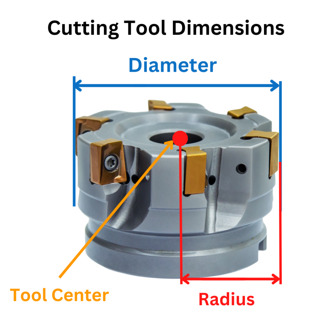
This code adjusts the path of the cutting tool based on the diameter of the cutter.
If you are looking towards the direction that the cutter is moving, the tool path is shifted to the left.
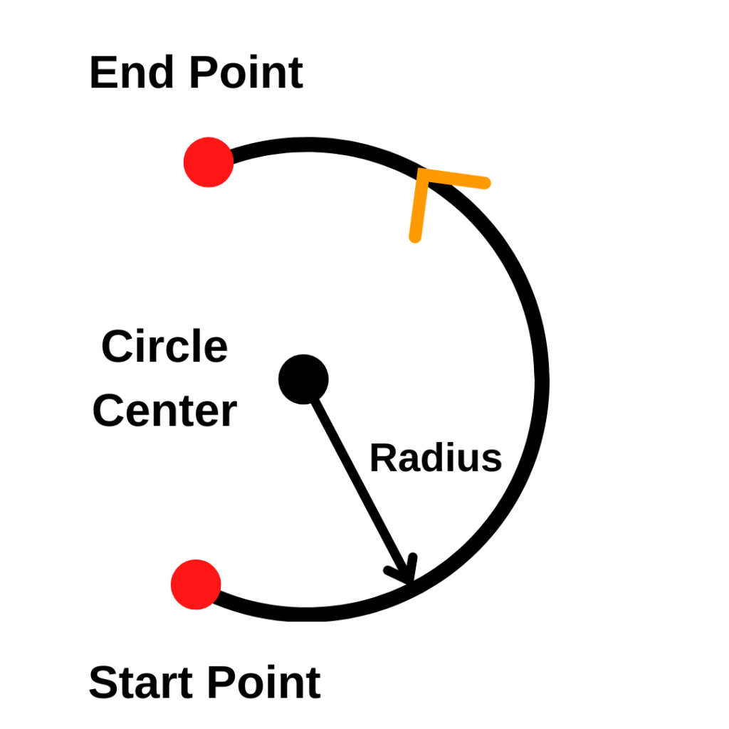
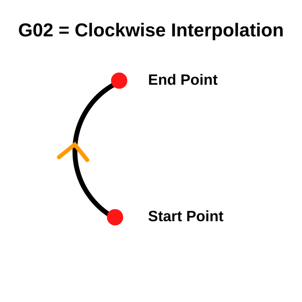
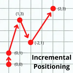
In the animation below, the tool path in the program is represented by the line with arrows.
There are also codes for using no cutter compensation (G40) as well as using cutter compensation right (G42).
What is cutter compensation
Cutter compensation is a CNC mode that allows the CNC controller to adjust for the size of the cutting tool.
Setting the size of the cutting tool allows you to use the same program with multiple different cutting tools.
Turning cutter compensation on tells the machine to shift the cutting tool either left with G41 or right with G42. The shift is half of the diameter of cutting tool, otherwise known as the radius.
Learn CNC Programming – It’s Easier Than You Think!
Learning G Code doesn’t have to be difficult…
If you know what to focus on.
Join our simple, easy-to-follow course, “G Code Made Easy: CNC Programming for Beginners“. We walk you through all the important codes – with simple explanations and real-world examples.
Want to become a super-skilled CNC programmer? Join now to take the shortcut to becoming a G Code Master today!
Make Learning G Code EasyVisualizing which way the machine will shift can be a little tricky. The shift happens as if you are looking towards the direction that the cutter is moving.
The two animations below show how the CNC will move when the other cutter compensation modes are active.
When cutter compensation is off (G40), the cutter will follow the tool path given in the program.
With cutter compensation right on (G42), the cutter will be shifted right and the left edge of the cutting tool will follow the tool path.
When to use a G41 code
The G41 command is useful in many milling operations such as contouring, pocketing, facing, and engraving.
Every operation that involves facing the cutter’s tip against the workpiece needs to account for the diameter of the cutting tool to avoid overcutting.
The G41 command is commonly found at the beginning of a program or subprogram and should remain activated until the machining operation ends. This doesn’t mean the entire program, but instead the individual sections of the program.
When using G41 or G42, the toolpath runs the cutter’s edge along the tool path instead of the centerline of the cutter.
Cutter sizes and D offsets
Even if you were to buy two of the same cutters, it is likely that there is a small difference in size between them. This difference in size is accounted for using offsets.
There are H offsets and D offsets that can be used when CNC machining.
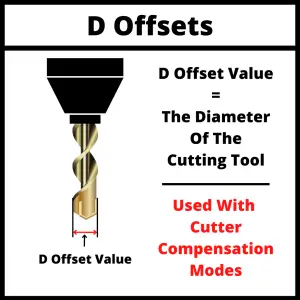
Because we are talking about cutter compensation with G41, we are going to focus on D offsets.
D offsets are stored in your machine’s controller, and they store the diameter of your cutting tool.
Now usually when the machine reads the coordinates given in the program, it moves the center of the cutting tool to that position. This can make it difficult to get the correct size especially when using different or multiple cutters.
Telling the machine the size of the cutters with your D offsets allows it to account for them and run the same program with different tools and get the same size part.
If you didn’t have cutter compensation, then you would need to create a new version of the program every time you wanted to use a new tool.
Using the tool offset table for cutter compensation
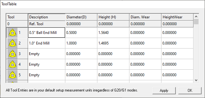
The Tool Offset Table, sometimes called Tool Table or Offset Library, is simply a table that the operator uses to store the offset values. This can include both diameter (D) and tool length (H) offsets.
Tool offset tables vary and some machines will only store one type of offset.
This means you may need to store both your diameter and tool length offsets in a D offset.
Some other machines may allow you to store the diameter and length of a cutting tool in the same offset number. The setup varies by machine so check yours out to make sure you know how it works.
The purpose of the Tool Table is to tell the CNC machine what the dimensions of the cutting tool are. This includes radius and length.
G41 programming format
There are multiple ways of formatting a G41 command:
- G41 D1. When the G41 code is used with a D offset it is meant to be used on a machine with a built-in tool table in the controller. G41 turns on cutter compensation left and D1 tells the machine to adjust the tool path based on the size stored in the first D offset.
- G41 P2. The P value is the radius of the tool used in the operation. This format is used more often on hobby level machines.
- G41 X2. This format is the same as using the P value.
Focus on learning the first format unless you plan to only ever use simple home level machines.
G41 vs G42
There are two different cutter compensation modes that can be used:
- G41 for cutter compensation left
- G42 for cutter compensation right
The direction of the shift is relative to the cutting tools direction of movement.
G41 is used when climb milling, which is the most common type of milling used.
G42 is used when conventional milling. Conventional milling sounds like it would be the standard, but in reality it is rarely used.
When climb milling, the cutter moves in the same direction as the stock feeds, which means that the workpiece produces less resistance to the cutting as the chips fall behind the cutter.
This type of milling helps prolong the life of the cutters and create a better surface finish. This is the most commonly used milling method CNC machines.
On the other hand, with conventional milling the cutter runs in the opposite direction of the stock feed, which means that the cutter will have more resistance against the workpiece and cause more tool wear resulting in a shorter tool life.
Which code cancels cutter compensation?
Cutter compensation with G41 is canceled by using the G40 code which cancels all active cutter compensation modes.
Alternatively, G41 can be canceled by switching to cutter compensation right by using the G42 code.
The two main things to pay attention to when using G40 to cancel cutter compensation are:
- Cancel cutter comp when you are off the part more than half the diameter of the cutter
- Make a move when canceling cutter compensation
Canceling off the part enough keeps the machine from running back into the part.
Making a move forces the machine to move in a consistent way. Some machines can react unexpectedly if no move is made when canceling cutter compensation. The machine basically thinks it has teleported locations.
Don’t teleport your CNC. Make a move when canceling cutter compensation.
Other types of compensation
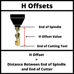
The other main form of compensation is tool length compensation.
Tool length compensation is turned on with either G43 or G44. Although G44 is almost never used. G43 is by a super wide margin the most often used tool length compensation.
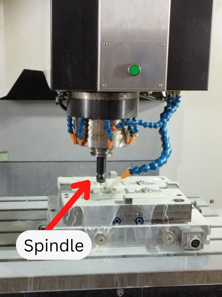
Tool length compensation accounts for the length of the cutting tool relative to the end of the spindle.
Tool length compensation is canceled with the G49 code.
Ready to master CNC programming?
Join our simple, easy-to-follow course, ‘G Code Made Easy: CNC Programming for Beginners’ and take the shortcut to becoming a G Code Master today!
Master G Code Today