What kind of coordinate system is used in CNC machining?
Almost every CNC machine uses a Cartesian coordinate system based on an X, Y, and Z-axis.
The coordinate system allows the machine to identify locations, move in specific directions and establish positions in a three-dimensional space.
Coordinate systems are formed by the axes (X, Y & Z), planes, and an origin where the three axes meet.
Using an X, Y or Z code in a CNC program tells the machine to go to a specific location along those axes. Location changes can be in one or more axes.
If only a Z axis coordinate is given then the machine will only move in the Z axis. This is the same for the other axes as well.

Ready to master CNC programming?
Try the free 30 minute intro course to see how simple and easy G code can be. Take the shortcut to becoming a G Code Master today!
Terms to know
To understand the coordinate system used by CNC machines, you need to first understand a few terms and concepts.
Coordinates
A coordinate is a location given in one or more axes.
Axis or plural axes
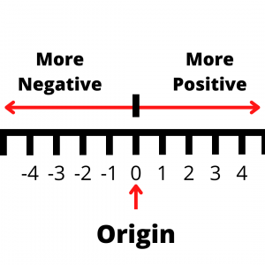
An axis is a straight line.
Along this straight line, each axis has a positive and a negative side.
The negative side continues on forever with larger and larger negative numbers. -1, -10, -99, -20,346 on til negative infinity.
On the other end of the axis are larger and larger positive numbers. 1, 5, 24, 578, 356,728 and on til positive infinity.
The two sides of the axis are separated by a center point.
At the center point the value of the axis is 0. This is called the origin.
Origin
The origin is the zero location of one or more axes.
Typically, when talking about origins we are referring to the zero location of multiple axes.
CNC mills are usually 3 axis machines and lathes are 2 axis. Both types of machines can have more axes but let’s keep things simple.
Less axes are usually easier to understand so let’s start with 2 axis coordinates.
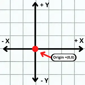
With two axes, the origin would be the (0,0) location.
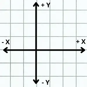
The is the location where the two straight line axes cross. This could be any two axes (XY, YZ, XZ) but generally we are referring to the X and Y axes. (0,0) is (X=0, Y=0).
Note that the two axes are perpendicular, or at 90 degrees to each other.
When talking about three axes, we are referring to the X, Y and Z axes.
When working with three dimensional coordinates, the origin is the spot where all three axes meet.
This is the (0,0,0) location.
Each of the axes are still perpendicular to each other. The order of axes is the same as before with the Z axis added on so (0,0,0) is (X=0, Y=0, Z=0).
Plane
A plane is a two-dimensional flat surface.
The most common one when talking about CNC machines is the XY plane. The XY plane is shown as the grid in the picture above.
The plane consists of all the possible coordinate location combinations possible in the X and Y axes.
There are three different types of plane combinations: XY, YZ, and XZ, and each plane has four quadrants with corresponding negative and positive values, two axes and an origin.
Quadrant
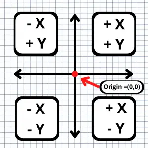
A quadrant is an area of the coordinate system plane. The four quadrants are shown below.
Quadrant 1 has positive X and positive Y values.
Quadrant 2 has negative X and positive Y values.
Quadrant 3 has negative X and negative Y values.
Quadrant 4 has positive X and negative Y values.
CNC machinists will want to pay attention to what happens when their machines switch quadrants.
Often changing the direction of travel from one direction to another will result in small defects or unintended features on the workpiece depending on the quality of the CNC machine.
Understanding Cartesian coordinates on a CNC machine
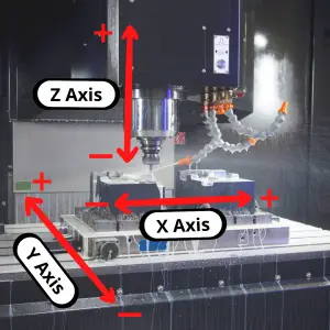
Usually, an easy way to understand the coordinate system for your CNC machine is to follow the Right-Hand Rule.
Hold your hand out palm up with your thumb and index finger pointed outwards, and your middle finger pointed upwards.
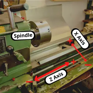
Place your hand in front of your CNC machine, aligned with the machine’s spindle, and you’ll see the axes line up perfectly.
- The thumb is the X-axis.
- The index finger is the Y-axis.
- The middle finger is the Z-axis.
The three fingers point to the positive side of each axis. The negative side is in the opposite direction.

Let’s compare that to our 3 axis mill to see how they line up.

How are coordinates used in CNC machining?
Most CNC machines use a conventional cartesian coordinate system and assign the order of axes movement as follows:
- X-axis allows movement “left” and “right”
- Y-axis allows movement “forward” and “backward”
- Z-axis allows movement “up” and “down”
However, there are a few exceptions to this rule, that will depend on the machine model or manufacturing company.
Some machines can switch the Z and Y axis, which can lead to confusion. Be sure to check all these details in your machine’s manual.
Movement in the coordinate system is related to the movement of your cutting tool. Many times, the cutting tool may not move in one or more axes but instead the control will move the table to act as if the tool moved.
Machine reference point
Every CNC machine has its own origin point or Home location that will serve as the machine’s coordinate system’s origin.
The machine reference point is a known point for the CNC machine.
You might move the zero location using a work offset such as G54, but the machine is calculating everything based off the reference point.
The CNC control allows you to do this to make the program easier to create and understand.
Work coordinate system
A work coordinate system sets a new origin location for the machine to use when running the CNC program.
You wouldn’t want to program to random coordinate locations in your machine. You also wouldn’t want to make a new program every time you wanted to make the same part on a different CNC machine.
The solution is a work coordinate system.
We touched on it earlier but using a work offset such as G54, G55 or one of the others commonly available on CNC controllers allows you to set your part or a fixture as the origin location.
Once the part or fixture is set as the X, Y and Z zero location, the program can be run.
Using a work coordinate system or work offset allows the CNC programmer and operator more flexibility in their programs and setup.
Often the work offset origin location will be either be where a corner of the part or the center of the part intersects the top surface.
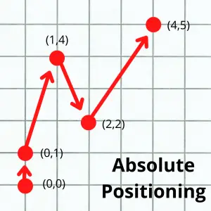
Absolute vs incremental coordinates
Everything we have talked about so far has been discussing absolute coordinates.
Absolute coordinates are a type of coordinates that are based on a fixed origin (zero) location.
In CNC machines, absolute coordinates are set using the G90 code.
There are exceptions but most CNC programs are mainly written using absolute coordinates.
The other type of coordinates that can be used are incremental coordinates.
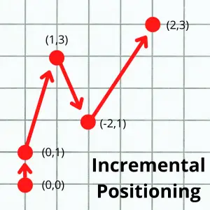
Incremental coordinates have a constantly changing origin location. Each time the CNC machine moves to a new location, that location becomes the origin.
In other words, each new move is relative to the machine’s current location.
Incremental coordinates are set using the G91 code in a CNC program. They are usually reserved for specific, repetitive features such as a series of holes that need to be drilled or something similar.
The pictures above show the same machine movement in the two different positioning modes. The locations given to the machine are given in parentheses ( ).
Polar coordinates
Most beginners don’t need to be too concerned with polar coordinates, but it is still helpful to be aware that they exist.
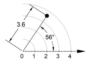
Polar coordinates are another way of specifying machine locations, like Cartesian coordinates.
Instead of X, Y and Z locations, polar coordinates use a radius, an angle, and a Z location.
Polar coordinates vs cartesian coordinates
Polar coordinates make calculations easier with circular motion, arcs, and circular paths.
On the other hand, Cartesian coordinates make linear movement easier to comprehend, and it is far more commonly used.
CNC machines are set to operate with a cartesian system by default. However, most CNC machines and controls include the option to use polar coordinates if needed.
CNC machines with multiple axes
Hobbyist CNC machines usually work with three axes (X, Y, & Z) as explained above.
Industrial grade machines can often be found with one or more additional axes. The most common is the addition of a rotary 4th axis.
4th, 5th and 6th axis machines are not uncommon.
Each of these axes rotates around one of the first 3 axes. The 4th axis rotates around X. The 5th around Y. The 6th around Z.
Ready to master CNC programming?
Try the free 30 minute intro course to see how simple and easy G code can be. Take the shortcut to becoming a G Code Master today!