If you’ve ever watched a CNC machine start a program and wondered how it knows where your part is — that’s G54.
Before the machine can cut anything, it needs a reference point. That reference point is called a work offset, and G54 is the code that activates it. It’s one of the first codes you’ll see in almost every CNC program, and understanding it makes the rest of CNC programming click.
This page covers what G54 does, how it relates to G55 through G59, and why you’ll want it in every section of your program — not just the beginning.
Key Takeaways
- G54 sets the work coordinate zero — it tells the machine where your part is
- G54 through G59 are all work offsets; they work the same way
- G54 is a modal command — it stays active until you change it
- Most CNC programs include G54 at the start of every operation section, not just once
- Always include the correct work offset in your safety lines to avoid machine crashes
| G54 – At A Glance | |
|---|---|
| Function | Work coordinate system selection |
| Type | Modal (Group 14) |
| Default offset | Yes — G54 is the most common starting offset |
| Related codes | G55, G56, G57, G58, G59, G53 |
| Cancelled/changed by | Another work offset command (G55–G59) or G53 |
What Does G54 Do?
G54 tells the CNC machine where your part is located.
More specifically, it activates a stored coordinate location called a work offset — or work coordinate system (WCS). That stored location defines where zero is on your part. Once G54 is active, every X, Y, and Z move in your program is measured from that zero point.
Think of it like GPS coordinates you saved to a preset. When you call G54, the machine knows exactly where to go to find your part.
G54 is a modal command
Once you call G54, it stays active for the rest of the program — even if you restart.
That type of command is called a modal command. Modal means it stays on until you turn it off or switch to something else. G54 stays active until you call a different work offset like G55 or G56.
This is important to understand because it can cause problems if you’re not careful. If the wrong offset is active when the machine starts cutting, it will machine in the wrong location.
That’s why most CNC programs include safety lines at the start of each section. Safety lines reset all the key modes — including the work offset — so you always know what state the machine is in before it cuts.
G54 vs. G55–G59
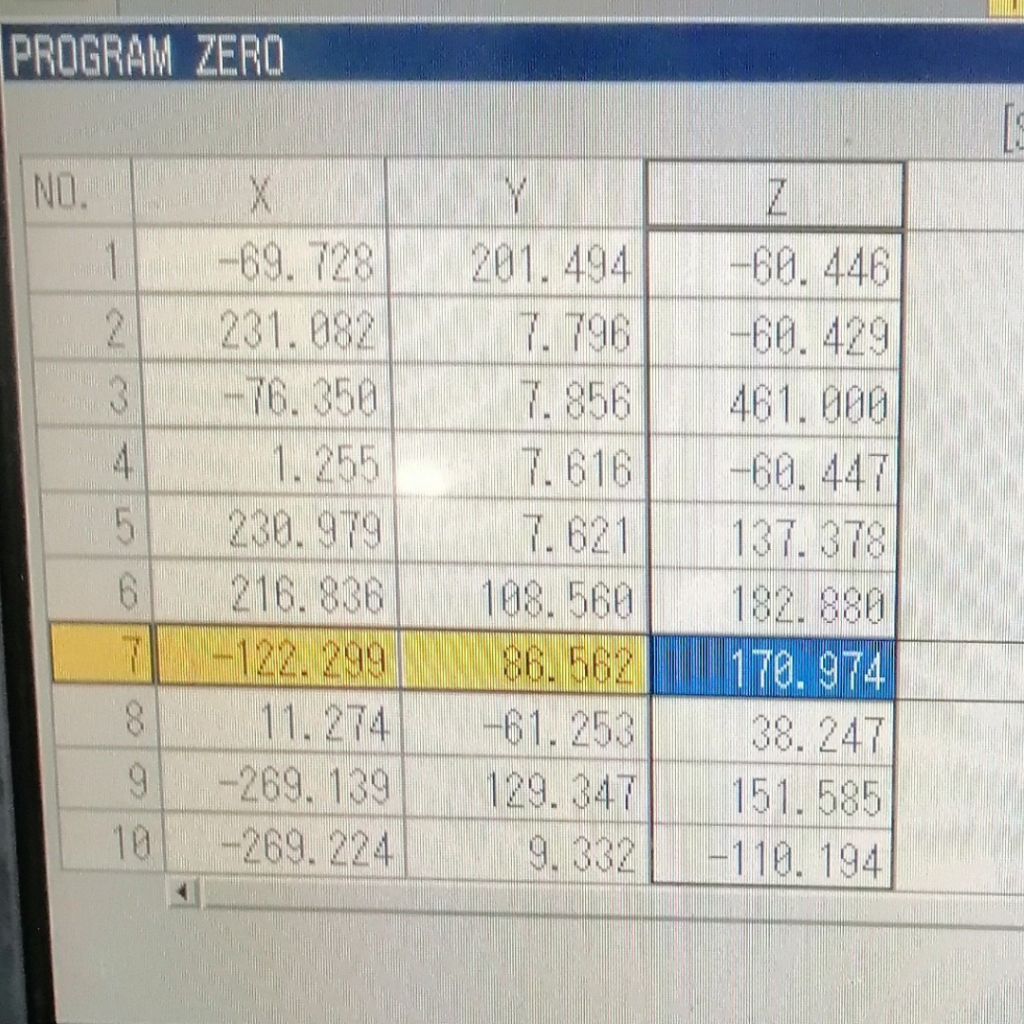
G55, G56, G57, G58, and G59 all work exactly the same way as G54. They’re just additional slots for storing different zero locations.
Each one holds a different set of X, Y, and Z coordinates. You set those coordinates in the machine’s offset table, then call the matching code in your program.
Work offsets work like presets on your radio, except you store a location instead of a radio frequency. You can then call it up quickly and switch between them as needed.
Common reasons to use multiple work offsets:
- Machining the same part in two different setups (Op 1 and Op 2 on the same fixture)
- Running multiple parts on one fixture at the same time
- Referencing different faces of the same part
G54 is used first because it’s the default — most programs only need one work offset, so G54 is the go-to.
The picture below shows how multiple work offsets can be set in a CNC and how they compare to the machine zero location.

Work Offset Visualizer — G54 through G57
Click a part to see which offset it uses and why.
Offset values are examples. Your actual values depend on how the part is fixtured.
A G54 Code Example
Here’s what G54 looks like in a real program. This example drills holes, then counterbores them.
O1000                          (Program number)
T01 M06                        (Tool change - drill)
G90 G54 G00 X1.0 Y1.0         (Absolute mode, G54 offset, rapid to first hole)
G43 H01 Z1.0 M03 S800          (Tool length comp, spindle on)
G99 G81 Z-0.75 R0.1 F8.0      (Drill cycle)
X2.0 Y1.0                      (Next hole)
X3.0 Y1.0                      (Next hole)
G80 M05                        (Cancel canned cycle, spindle off)

T02 M06                        (Tool change - counterbore)
G90 G54 G00 X1.0 Y1.0         (G54 called again at start of new section)
G43 H02 Z1.0 M03 S600
G99 G82 Z-0.25 R0.1 P500 F5.0 (Counterbore cycle)
X2.0 Y1.0
X3.0 Y1.0
G80 M05
M30
Notice that G54 is called at the start of both the drilling section and the counterboring section — even though they use the same offset. That’s intentional. If you ever ran just the counterbore section by itself, the machine would still have the correct offset active.
COMMON MISTAKE – Only calling G54 at the start of the program.
If you ever run a single section of the code out of sequence — which happens more than you’d think — the machine picks up whatever offset was last active. That could be G55, G56, or something leftover from the previous job. Always include the work offset in the safety lines of each operation.
When to Use G54
G54 should appear at the start of every section of your program where a work offset matters — not just the beginning.
The most common place: right before your first positioning move after a tool change. That’s when the machine needs to know where it’s working.
A good rule of thumb: if you have a new tool change block, put a fresh safety line with G54 (or whichever offset applies) right after it.
Which Work Offset Is Used Most?
G54 is the most commonly used work offset. If your job only needs one setup and one zero location, G54 is what you’ll use.
G55 through G59 come into play when you need more than one zero point — multiple parts on a pallet, multi-op fixtures, or setups that reference different part features.
Most machines have at least G54–G59 as standard. Some controls offer extended work offsets beyond G59, but those six cover the vast majority of setups.
Related Codes Worth Knowing
G53 — Machine Coordinate System
G53 sends the machine to a location based on machine zero — the absolute home position of the machine itself, not your part.
It’s not modal. G53 only affects the single line it’s on, then the previous work offset takes back over.
You’ll typically see G53 used to send the spindle to a safe tool change position. Not all machines support it — and older controls may interpret it differently — so check your machine’s manual before relying on it.
G28 — Return to Machine Zero
G28 sends the machine through an intermediate point and then to machine zero in one or more axes.
It’s commonly used in the program header or at tool changes to get the spindle out of the way before the next operation.
How G10 Affects Work Offsets
G10 lets you change an offset value from inside the program, without going into the offset table manually.
The format looks like this:
G10 L2 P1 X1.5 Y2.3 Z3.0- L2 tells the control you’re setting a work offset
- P1 specifies which offset (P1 = G54, P2 = G55, and so on)
- X, Y, Z are the new coordinate values
G10 is an advanced feature. The format isn’t the same on every control, so always check your machine’s programming manual before using it. It’s not something beginners need to worry about right away.
FAQS
What is G54 in CNC programming?
G54 is a work offset command. It activates a stored coordinate location that tells the machine where your part’s zero point is. All moves in the program are measured from that location while G54 is active.
What is the difference between G54, G55, G56, G57, G58, and G59?
They all do the same thing — they each activate a different stored zero location. G54 is just the first one and the most commonly used. You’d use multiple offsets when you have more than one part or setup on the machine at the same time.
Does G54 need to be in every tool change block?
It’s good practice to include it at the start of every operation section, not just the first one. That way, if you ever run one section of the program on its own, the correct offset is always set before the machine starts cutting.
Is G54 the same on all CNC machines?
Yes — G54 through G59 are standard across Fanuc, Haas, Mazak, and most other CNC controls. The way you set the offset values in the machine’s offset table may vary slightly by control, but the G54–G59 commands work the same way.