
Table of Contents
ToggleWhat is a modal command?
Modal commands are a type of CNC code that stay active once turned on until the code is either turned off or switched to another code in the same group.
For example, if left cutter compensation is turned on with G41 it will stay on until either the G42 code switches the machine to right cutter compensation or the G40 command is used to turn off cutter compensation altogether.
Want to learn more about CNC G Code?
Why and how are modal commands used?
Modal commands are useful because they increase productivity.
Modal commands can save time for the CNC programmer and make the CNC program smaller.
Using modal codes allows you to not have to write the same code repeatedly. This also has the added benefit of making the program easier to read.
By using modal commands you set the machine modes once and then switch them as needed.
A good example of this is your unit mode.
Most programs will be written in either inches or millimeters. It is not common for a program to switch between the two unit types.
Using modal commands allows you to use the G20 code and set the machine in inch mode at the start of the program and leave it on.
Without the capability to use modal commands, you would need to tell the machine that every new line of code was in inches.
This would make for a very busy, hard to read program with a bunch of codes repeated throughout.
Modal commands make the programming easier to create and easier to read.
Remember you can only have one modal command from the same group active at a time.
Also, there are some commands which are one-shot codes. This means they only affect the line they are used on.
The various modal groups are shown below.
Modal command groups
To really drive the point home, remember:
You can only have one modal code active from each group.
If you use G20 to put the machine in inch mode and then use the G21 command to put the machine in metric mode, they are not both active. The G20 command gets turned off when the G21 command is turned on.
Some of the groups of codes have a cancel command which can be used to turn all codes in the same group off.
Not every code group has a cancel command though.
For instance, you will always be in either G20 (inches) or G21 (mm). It is not possible to turn both off. One or the other must be active.
If a code group has a cancel command, it is discussed in the individual group sections below.
Movement [G00, G01, G02, G03]
One of the most frequently used group of codes is movement codes.
CNC machines need to move to cut, drill, and grind parts along with many other functions.
Many times, large portions of your CNC program will be exclusively movement codes as the machine performs its cutting operations.
In the movement group of codes there are four different codes:
- G00 – rapid movement
- G01 – linear interpolation (straight line movement)
- G02 – circular interpolation, clockwise (circular movement)
- G03 – circular interpolation, counterclockwise (circular movement)
You move with G01, G02 and G03 to make cutting movements to make all kinds of shapes and cuts on the part, but what about G00?
G00 is rapid movement and is used to move the machine as quickly as possible when it is not in the process of cutting.
Moving rapidly reduces the total machining time, otherwise known as cycle time. While this might not make a huge difference for making one part in your garage, shaving a minute off each part for an order of 1,000 pieces really adds up.

Units [G20, G21]
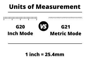
We talked about it above but the codes used to set your units are very important.
G20 sets the machine in imperial units (inches) and G21 sets the machine in metric units (mm).
Switching between units is not advised. Set your units and stick with them.
Cutter compensation [G40, G41, G42]
Cutter compensation is a mode that allows the machine to adjust for the size of the cutting tool.
This allows the same program to be used with multiple different cutting tools. Without cutter compensation, you would need to write a new program each time you had a new cutter.
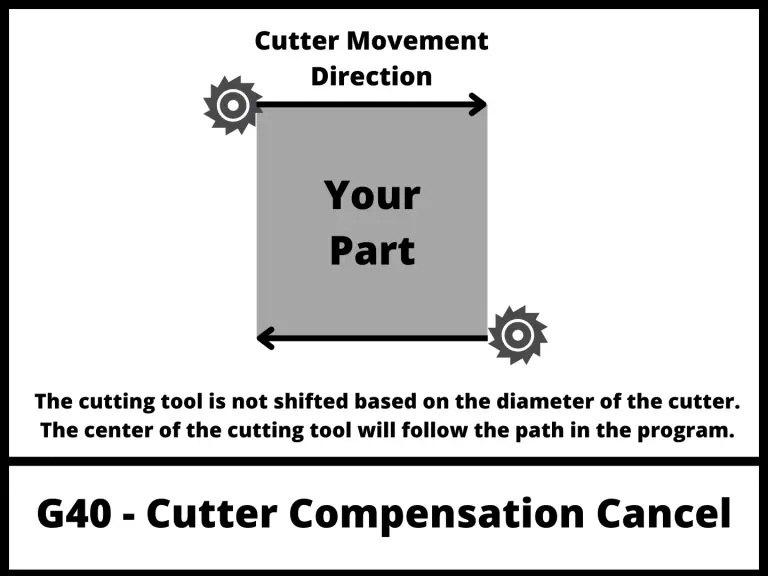
The first code in the group is the cutter compensation cancel command, G40. When this code is active, the CNC will move the center of the cutting tool along the tool path listed in the program.
This is useful when you want to drill a hole at a specific location.
The two cutter compensation modes which cause the machine to adjust the tool path are:
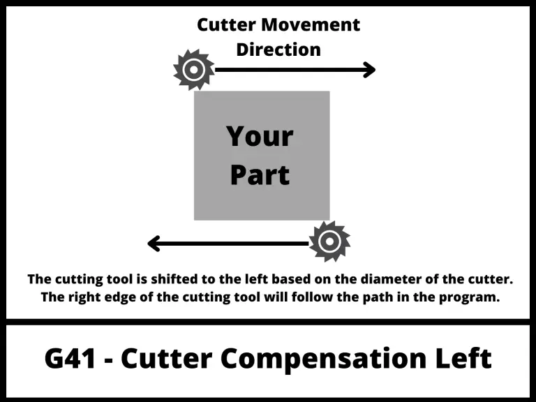
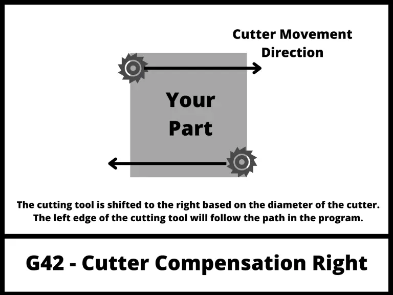
Both modes adjust the path of the cutting tool so that the edge of the cutter follows the toolpath of the program.
G41 is used when climb milling and G42 is used when conventional milling.
G41 is used far more often than G42.
Both G41 and G42 take into account the D offset value to tell the CNC how much to adjust the tool path.
The D offset value is listed when turning on cutter compensation. For example, to turn on left cutter compensation with the first D offset the line of code would be:
G41 D1
Tool length compensation [G43, G49]
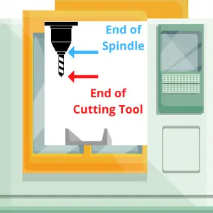
Just like the diameter of the cutter needs to be accounted for, so does the length of the cutting tool.
G43 is the code to turn on tool length compensation.
This code is used along with an H offset value which is stored in the CNC controller similar to the D offsets used in cutter compensation.
Tool length compensation is used for many of the same reasons cutter compensation with G41 and G42 is used.
It allows the machine to adjust for the length of the cutting tool and not require a new program to be created each time the tool is changed.
Technically, G43 is for positive tool length compensation and G44 is for negative tool length compensation.
For anyone just learning about modal commands, they should ignore G44 for the time being.
G44 is not used often and is not something that a beginner can expect to deal with.
Focus on G43 and G49 when first learning CNC programming.
Speaking of G49. G49 is the code to cancel tool length compensation.
Remember cancel just means turn it off.
You might think that you would need to turn off tool length compensation much like you would with cutter compensation, but this is rarely true.
Instead, the machine will switch between tools by using different H offsets for different length cutters.
When tool length compensation is off using a G49 code, the machine will move the tip of the spindle to each new location instead of the tip of the cutter.
Because you will almost always have a cutting tool in your spindle, tool length compensation with G43 is almost always on.
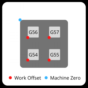
Fixture/work offset [G54-G59]
Fixture offsets, sometimes called work offsets are how the machine knows where your part is located in the machine.
They tell the machine the zero location in the three axes (X, Y, & Z). The machine will execute the program based on this zero location.
Using work offsets allows you to easily set up for a different part or even use one program to run multiple parts at once.
You can tell the machine the location of your first part by using G54, run your program then set the work offset to G55 so the machine knows where the second part is and proceed to run the same program again.
Just like your D and H offsets allow flexibility in your CNC programming and setup, work/fixture offsets with G54-G59 do the same.
It should be noted that G54 through G59 are the most common work offsets used and can be found on most machines.
In addition to these six offsets, most machines (especially new models) will be able to use many more offsets. How they are used varies from machine to machine so check your machine manual.
Positioning mode [G90, G91]
Positioning modes tell the CNC machine how to interpret each new location it is given.
There are two types of positioning modes which can be used:
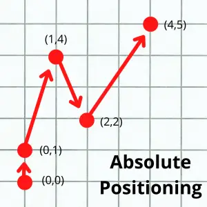
Absolute positioning with G90 tells the machine that all dimensions are measured from the datum/origin (0,0,0). This is a fixed point in the machine that will not change unless the work offset is changed.
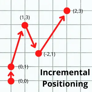
Incremental positioning with G91 tells the machine that each new location becomes the zero location (0,0,0).
The pictures below show the same tool path in both positioning modes. The coordinate location of each new move is listed in parentheses ().
Canned cycles [G80, G81, G82, G83, G84, G85, G86, G87, G88, G89]
Canned cycle are modal commands which are used for programming repetitive CNC operations.
They have the benefit of making your CNC program both shorter and easier to read and understand.
Canned cycles are a big topic on their own so I will only include a brief description of what each code is used for. If you need more information about any of the individual canned cycles, then click the links below:
- G73 – deep hole peck drilling
- G74 – left-hand tapping cycle
- G80 – canned cycle cancel
- G81 – simple drilling cycle
- G82 – drilling cycle with dwell
- G83 – peck drilling cycle
- G84 – right-hand tapping cycle
- G85 – boring cycle – feed in, feed out
- G86 – boring cycle – feed in, spindle stop, rapid out
- G87 – back boring cycle
- G88 – boring cycle – feed in, dwell, spindle stop, rapid out
- G89 – boring cycle – feed in, dwell, feed out
Plane returns [G98, G99]
Plane returns tell the machine how to act after finishing a canned cycle.
The two options are:
G98 returns to the point where the canned cycle was started.
G99 returns to the R plane, which is the point where the controlled feedrate (not rapid) started.

The R plane is lower than the initial point. This can allow for shorter machining time because the machine is not travelling as far.
Often a series of holes will be drilled and both G98 and G99 return codes will be used in the process.
The G99 code gets used when the machine is able to stick close to the part and move to the next hole.
The G98 code is used when the machine needs to retract further, for instance if you needed to avoid a clamp or something else in the way of your cutter.
G98 retracts further and takes longer but is generally the safer option.
You should be careful using both G98 and G99 though.
Pay close attention to the initial point (your Z height when starting the canned cycle) and your R plane (set with the R code in your canned cycle callout).
The initial point should be set at a level that is higher than any objects in the machine such as the part itself, clamps, fixtures, etc.
Plane selection [G17, G18, G19]
There are 3 codes that tell the machine which plane to work in:
- G17 for the XY plane
- G18 for the XZ plane
- G19 for the YZ plane
Most programs will be written using the G17 code and work in the XY plane.
Spindle commands [M03, M04, M05]

This group of modal commands controls the CNC spindle. They are:
Coolant [M07, M08, M09]
The next group of modal M codes controls the machines use of coolant.
Mist coolant is usually a combination of coolant and compressed air but this can vary from machine to machine and sometimes you may find that it is only compressed air or not even available on your specific machine.
Flood coolant is the normal CNC coolant mode where the machine floods the cutting tool and workpiece with coolant.
M07 modal command turns on the mist coolant and it will be directed to the material cutting.
Other modal commands
There are many other modal commands which can be used for CNC programming.
They vary by machine and not all machines will have each type of modal code.
The codes laid out here are the most common modal commands and will give anyone trying to learn CNC programming a good start towards learning the ins and outs of modal commands.
Frequently asked questions about modal codes
Modal vs one shot codes
While there are a lot of modal codes, not every CNC code is modal.
There are also one-shot (non-modal) commands as well. These codes only affect the line they are used on.
A couple of the commonly used one-shot codes are:
- G04 – dwell
- G29 – zero return
What happens if I don’t set a modal code?
When the CNC machine starts up it sets the machine to various default modes as set in the setup parameters of the machine.
It is never advised to rely on the startup modes of the machine to create your program. It is always better to call out any needed codes specifically in your program.
If you don’t set a modal command, the machine will remain in the default modes as set in the system parameters.