G41 turns on cutter compensation left. It’s a modal command, which means it stays active until you turn it off.
When G41 is active, the CNC shifts the cutting tool to the left of the programmed path — relative to the direction the tool is moving. Instead of the center of the cutter following your coordinates, the edge of the cutter follows them.
Key Takeaways
- G41 activates cutter compensation left — the tool shifts left relative to its direction of travel
- Use G41 for climb milling, which is the standard in most CNC milling operations
- The amount of shift comes from the D offset stored in the tool offset table
- Always cancel G41 with G40, and make a move when you do — never cancel on the part
- G41 lets you run the same program with different cutter sizes without rewriting coordinates
| G41 – At A Glance | |
|---|---|
| Function | Cutter Compensation Left |
| Format | G41 D[offset number] |
| Type | Modal (Group 7) |
| Cancelled by | G40 |
| Related codes | G40 (cancel), G42 (comp right), G43 (tool length comp) |
What Does G41 Do?
G41 tells the CNC controller to shift the tool path to the left based on the diameter of the cutter. The shift amount is half the cutter diameter — the radius.

Without cutter compensation, the controller moves the center of the tool to the programmed coordinates. That means the edge of the cutter is cutting half a diameter away from where you told it to go. For rough cuts this might be fine, but for precise contour work it will give you the wrong part size.
G41 fixes that. When it’s active, the edge of the cutter — not the center — follows your programmed path.
What is cutter compensation
Cutter compensation is a CNC mode that adjusts the tool path based on the size of the cutting tool.
Two cutters from the same manufacturer, even the same model, won’t be exactly the same diameter. They’re close, but not identical. Cutter compensation lets you store each tool’s actual diameter in the offset table and have the machine account for that difference automatically.
The direction of the shift is always relative to the direction the tool is moving. If you’re looking in the direction the tool travels, G41 shifts left, and G42 shifts right.
- G40 — no compensation (tool center follows the programmed path)
- G41 — cutter compensation left
- G42 — cutter compensation right
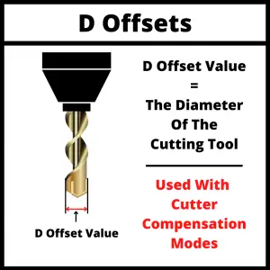
D Offsets and Cutter Size
G41 works with D offsets. A D offset stores the diameter of a specific cutting tool in the machine’s controller.
When you call G41 D1, you’re telling the machine: turn on cutter comp left, and use the diameter stored in offset number 1.
Even two identical endmills from the same box will have slight variations in diameter. Measuring each one and entering the actual diameter into the offset table is how you get consistent part sizes across tools.
The Tool Offset Table
The tool offset table (sometimes called the offset library or tool table) is where you store these values. Depending on your machine, it may store diameter offsets separately from length offsets, or combine them under the same offset number.
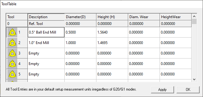
Check your machine’s documentation to know which format yours uses. Some machines use D offsets for diameter only. Others store both diameter (D) and length (H) under a single offset number per tool.
The bottom line: the table tells the machine the physical size of each cutter. G41 reads from that table to know how far to shift the tool path.
G41 Programming Format
There are multiple ways of formatting aThe most common format is:
G41 D1G41 turns on cutter compensation left. D1 tells the machine to use the diameter stored in offset number 1. On most Fanuc-style controls and industrial machining centers, this is the format you’ll use.
Two other formats exist, mostly for hobby or entry-level machines:
- G41 P[radius] — directly specifies the tool radius as a number (e.g., G41 P0.25 for a 0.5″ diameter endmill)
- G41 X[value] — same function as the P format on some controls
If you’re working on industrial equipment, learn the D offset format. That’s what you’ll use in a real shop.
G41 Example Program
Here’s a simple contour milling example using G41:
G90 G54 G00 X-1.0 Y0        (Rapid to approach position, outside the part)
G43 H01 Z0.1                 (Tool length comp, move to clearance height)
S1200 M03                    (Start spindle at 1200 RPM)
G01 Z-0.25 F10.0             (Plunge to depth)
G41 D01 X0 Y0 F15.0          (Turn on comp left, lead-in move to part)
X4.0                         (Mill along the part edge)
Y3.0
X0
Y0
G40 X-1.0                    (Cancel comp, lead-out move — off the part)
G00 Z1.0                     (Rapid to safe Z)
M05                          (Stop spindle)
Notice that G41 is turned on during a move (the lead-in), and G40 is also canceled during a move (the lead-out). Both moves are made away from the part. This is the correct way to use cutter compensation.
G41 vs G42
G41 and G42 are the two cutter compensation directions:
- G41 — shifts left relative to tool travel direction (climb milling)
- G42 — shifts right relative to tool travel direction (conventional milling)
Climb milling is standard on CNC machines. The cutter and the workpiece feed in the same direction, chips fall behind the cutter, and tool life is better. G41 is almost always the right choice.
Conventional milling (G42) cuts against the feed direction. The tool has more resistance, generates more heat, and wears faster. You’ll rarely program it intentionally, but you might encounter it in older G-code programs.
Canceling G41 with G40
G41 is canceled with G40. When you’re done with your comp operation, you need to turn it off correctly.
Two rules that matter:
1. Cancel cutter comp off the part. When G40 executes, the tool shifts back to center. If you cancel while the cutter is against the part, the tool will move into the workpiece. Cancel with at least half the cutter diameter of clearance.
2. Always make a move when canceling. Include a coordinate in the same block as G40 — or in the next block. Some controllers react unexpectedly if no motion is programmed when cutter comp is canceled. The machine has to know where to move..
COMMON MISTAKE – Canceling G41 while the cutter is still on the part
When cutter comp cancels, the tool shifts back to its center position — which means it moves into the part.
To avoid problems when canceling cutter comp, always lead out to a clear position before canceling. Cancel off the part and make a move when you cancel.
When to Use G41
G41 is used during climb milling, which is the standard milling method on CNC machines.
In climb milling, the cutter moves in the same direction as the feed. The chips fall behind the cutter, there’s less resistance against the tool, and you get a better surface finish with less tool wear. G41 positions the tool correctly for this cut.
G42 is used for conventional milling — where the cutter moves opposite to the feed direction. It’s rarely used in CNC work, but you’ll encounter it on some older programs.
Common operations that use G41:
- Contouring (milling along a profile)
- Pocketing
- Facing
- Engraving
Any operation where the cutter’s edge needs to follow a precise profile should have cutter compensation active.
Other types of compensation
Cutter compensation (G41/G42) handles the diameter of the tool. There’s also tool length compensation, which handles how long the tool is.
Almost every program you write will use G43 along with G41 or G42. The two work together: G43 sets the correct depth, G41 or G42 sets the correct diameter offset.
FAQS
What’s the difference between G41 and G42?
G41 shifts the tool to the left of its travel direction — used for climb milling, which is standard on CNC machines. G42 shifts right and is used for conventional milling, which is rare in CNC work.
What happens if I forget to cancel G41?
If cutter compensation stays active into a tool change or the end of the program, most controllers will alarm out. On some older machines, uncanceled comp can cause unexpected moves. Always cancel with G40 before a tool change or end of program.
Do I need to use cutter compensation on every operation?
Not always. Drilling, tapping, and boring cycles don’t need cutter comp — the tool cuts on its tip, not its side. Cutter comp is mainly for milling operations where the side of the cutter is cutting a profile or contour.
What is a D offset in G41?
A D offset stores the diameter of a cutting tool in the machine’s offset table. When you program G41 D1, the machine reads the diameter from offset 1 and uses it to calculate how far to shift the tool path.