Types of compensation
CNC machines have three main types of compensation:
- Cutter compensation/tool diameter compensation
- Tool length compensation
- Work/fixture offsets
These compensation modes allow the machine to accommodate for things such as the location of a part in the machine or the size of a cutting tool.
Compensation allows the machine to adjust how it reads the CNC G code so that the same program can be used in multiple ways.
Using compensation modes allows the CNC to run the same program and get the same results even if the factors we mentioned above (cutting tool, workpiece location) are changed between runs.
The machine will have no problem adjusting for a new cutter as long as we tell the machine the diameter and length of the new cutting tool.
The values that tell the machine how long the tool is or what its diameter is are called offsets.
There are multiple compensation codes and offset codes.
Luckily, the list isn’t long. Let’s go through them one by one.
Ready to master CNC programming?
Try the free 30 minute intro course to see how simple and easy G code can be. Take the shortcut to becoming a G Code Master today!
Cutter compensation/tool diameter compensation
The first type of compensation is compensation that accounts for the size or diameter of the cutting tool. This is often referred to as simply cutter compensation.
There are two types of cutter compensation.
Before we talk about what cutter compensation does when it is on, let’s talk about how to turn it off.
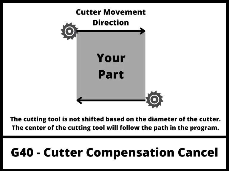
G40 – Cutter compensation cancel
The two cutter compensation modes are both modal commands.
This means that they stay on and in effect until they are changed or cancelled.
Selecting G41 or G42 switches between the two modes. If you want to turn off cutter compensation you will need to use the cancel command.
G40 is the off button for cutter compensation.
Calling it in your program will cancel any active cutter compensation.
Because modal commands stay on until changed or turned off, you often see cancel commands used in safety blocks of code found at the beginning of the program or a new section of the code such as when changing tools.
The illustration below shows how the CNC will move when cutter compensation is off.
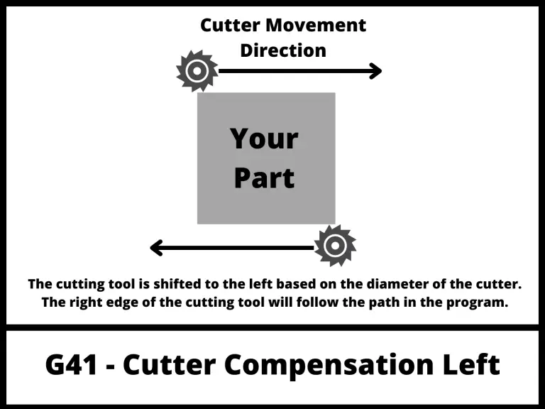
G41 – Cutter compensation left
G41 is the most common cutter compensation. It is used when climb milling.
The G41 code tells the CNC to shift the cutter to the left of the cutting path to account for the size of the cutter.
See the pic below for help understanding what that means in practice.
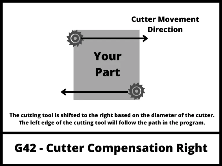
G42 – Cutter compensation right
G42 is used when conventional milling.
The G42 code tells the CNC to shift the cutter to the right of the cutting path to account for the size of the cutter.
G42 is not used nearly as often as the G41 code.
D offsets

Diameter (D) offsets are the location where the size (diameter) of the tool is stored in the CNC control.
D01 will be the offset where the size information is stored for tool #01. D02 will be for tool #02 and so on.
D offsets are set with the D code.
Tool length compensation
G43 – Tool length compensation +
G43 is the command to turn on tool length compensation.
Just like G40-G42, G43 is modal which means it will stay on until changed or canceled.
G43 is for positive tool length compensation. You should be aware there is also a negative tool length compensation mode (G44) but it is rarely used and not something that beginners should be worried about.
G43 is used frequently and you can expect to see it used in 99.9% of the CNC programs you will come across.
G49 – Tool length compensation cancel
Just like G40 cancels cutter compensation based on the diameter of the tool, G49 does the same for tool length compensation.
Like many other cancel commands, G49 can be found at the beginning or ending of different sections of code to ensure the machine is in the correct mode as tools are changed and different operations are performed.
H offsets

Height (H) offsets are the location where the length of the tool is stored in the CNC control.
This value is the difference in location between the end of the spindle and the end of the cutting tool.
H01 will be the offset where the length of tool #01 is stored. H05 will be for tool #05 and so on.
Height offsets are set with the H code.
Fixture/work offsets
Work offsets are used to tell the machine where it should reference all program values from.
For example, imagine if you wanted to machine four separate parts to be all the same. You could load all four parts into your CNC machine and set a work offset location for each separate part.
Once the work offsets are stored, you could call out the first work offset and then run your program.
Next you could call out the next work offset and run the same program again. This would run the same program in a new location resulting in two of the same part. And rinse and repeat as much as needed.
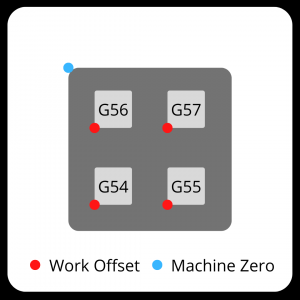
G54-G59 – Work offsets
G54 through G59 are the standard work offsets that you can expect to find on just about any CNC machine.
Work offsets identify an X, Y & Z coordinate zero location. Work offsets go by many other names such as program zero, part zero, zero location, etc.
Some machines may be capable of storing many more work offset locations, but it is best to concentrate on the most common codes first. Check your individual machine documentation to learn how to program with more work offsets.
If you are very new to CNC programming with G code then be on the lookout for a G54 code.
This is the first work offset and as a result is the most common one used. Often shops will only have a need for this single work offset. As shops and machine become more advanced you can expect to see more usage of additional work offsets.
Just like the other offset modes we have talked about; work offsets are also modal commands.
Expect to find them in the safety blocks of code and because they are important enough to be included in the safety block section, you should be very careful about making sure you have identified the correct work offset at all times in the program.
Ready to master CNC programming?
Try the free 30 minute intro course to see how simple and easy G code can be. Take the shortcut to becoming a G Code Master today!