What is a CNC offset?
Offsets are the adjustments that the CNC machine will make based on different features of the machine.
There are three types of offsets:
- Diameter offsets
- Height offsets
- Work offsets
Ready to master CNC programming?
Try the free 30 minute intro course to see how simple and easy G code can be. Take the shortcut to becoming a G Code Master today!
Types of CNC offsets
Each of the three offset types has a specific purpose.
They each allow for flexibility when running your program. This includes allowing you to use the same program even if you need to change cutting tools.
Height (H) offsets

The height offset refers to the location difference between the spindle and the cutting tool.
This difference in location is stored in the machines offset library. Height offsets are usually stored in the same number location as the tool.
For instance, T01 (tool 1) and H01 (height offset 1) or T05 (tool 5) and H05 (height offset 5).
This makes it easier to match up the necessary offset with the correct tool.
The G43 code is used to turn on tool length compensation using an H offset.
For example, G43 H01 turns on tool length comp with the first H offset.
Once tool length compensation is turned on with the G43 code, it will stay on until it is turned off with the G49 cancel code or switched to a new H offset such as H02 or H05.
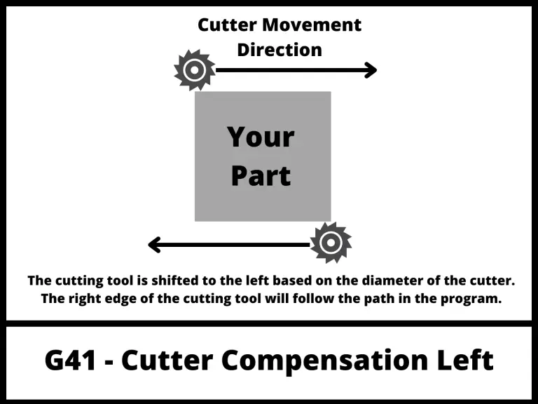
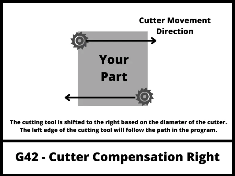
Diameter (D) offsets

While H offsets adjust for the length of the cutter, D offsets compensate for the diameter of the cutting tool.
D offsets are also stored in the machines offset library. D offsets are usually stored in the same number location as the tool they are used with.
T04 (tool 4) and D04 (diameter offset 4) would usually be matched together.
G41 and G42 are the two cutter compensation modes that are used with D offsets.
They tell the machine to adjust the path of the cutter so that the edge of cutter follows the path given in the CNC program. G41 shifts the cutter left and G42 shifts the cutter right.
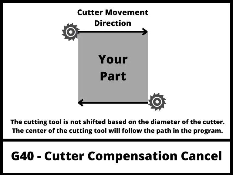
With cutter compensation off using the G40 code, the machine will move the center of the cutter along the path in the program.
This can make it difficult to get the correct size, especially when using different or multiple cutters.
Telling the machine the size of the cutters with your D offsets allows it to account for them and run the same program with different tools ang get the same size part.
If you didn’t have cutter compensation, then you would need to create a new version of the program every time you wanted to use a new tool.
Just like tool length compensation with G43, cutter comp with G41 and G42 are modal commands so those adjustments will stay on until switched or turned off with the G40 code.
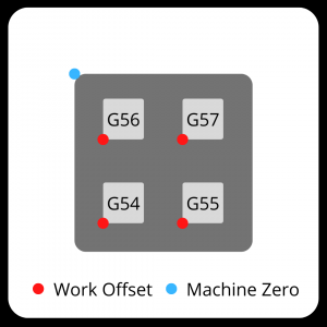
Work offsets (G54-G59)
Work offsets are basically the stored location of your part in the machine.
You use them to set the XYZ zero location when working in absolute positioning mode.
There are multiple work offsets available.
The six most common are G54 through G59. Most machines will also have others available, but the format varies from machine to machine.
Fanuc controls are one of the most common controllers. If they allow additional work offsets, the Fanuc format for using them is G54.1 P1, G54.1 P2 and so on. The P number is the additional offset.
In most cases the six offsets of G54 through G59 that are common on all machines will be more than enough.
One benefit of having multiple work offsets is how easy they make it to run multiple parts at once. You can set the work offset for multiple parts and run the same program with a new work offset each time.
This works well when you a fixture that holds multiple parts in your CNC.
Where are offsets stored?
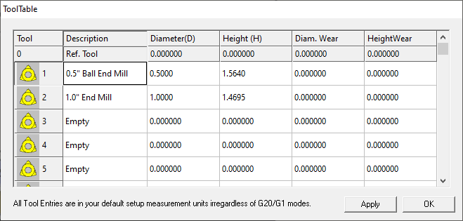
Offsets are stored in the tool offset table or library.
This tool table allows you to describe the different dimensions of the tool that will affect the program.
This includes the tool radius or diameter (D offset) and its length (H offset).

Some machines allow you to store the H and D offsets together in one offset. In this example, tool T01 would use both H01 and D01 as offsets.
Other machines may require the offsets to be stored individually.
When the offsets are stored individually, the programmer should maintain a system so that the offset numbers used are consistent.
In other words, the first H offset would always be stored in the 01 location and the first D offset would always be stored in the 51 location.
Having a system like this will help prevent errors in your program.
Ready to master CNC programming?
Try the free 30 minute intro course to see how simple and easy G code can be. Take the shortcut to becoming a G Code Master today!