What is a G code?
G code is the programming language used by CNC machines of all types.
This includes everything from mills and lathes to 3D printers and laser engravers.
G code consists of commands made up of letters and numbers that tell the CNC machine what to do. Most letters in the alphabet are used as codes to make the machine do something.
This can be a little confusing because while G code refers to the programming language used by CNC machines, there is also a large group of codes that are frequently used which start with the letter G. This group of codes is often referred to as simply “G codes”.
This post will cover the most common group of codes that start with the letter G, but we also have resources to help with the other letter codes if you need it.
Ready to master CNC programming?
Try the free 30 minute intro course to see how simple and easy G code can be. Take the shortcut to becoming a G Code Master today!
What types of codes are used in CNC programming?


The two largest groups of codes are G codes and M codes.
G codes are preparatory functions.
These codes prepare the machine to perform an action by setting various machine modes such as working in inches vs millimeters.
There are dozens of G codes which are used, and they vary somewhat from machine to machine.
The most common G codes are listed below.
For the most part, the commonly used G codes are consistent across the different machine makes but check your machine manual to be sure.
M codes are miscellaneous functions.
These are easier to remember as “machine functions” because this group of codes controls different parts of the CNC machine such as turning the spindle or coolant on and off.
The rest of the CNC codes consist of the remaining letters A through Z.
G and M codes are the only ones to worry about that have multiple codes within the same letter. In other words, there is a G01 and a G02 code. This isn’t true for other codes such as F, S, X, Y or Z.
Working with G Codes
G codes set various machine modes including turning them on and off.
Only one G code can be active at a time from each group.
If you use the G20 code to turn on inch mode then the machine will basically turn off metric (mm) mode. You can’t have both codes active at the same time.
These are called modal commands.
Some modal commands can be canceled (turned off) without setting another mode. For example, cutter compensation can be set to adjust left with G41 or right with G42. It can also be turned off (canceled) with G40 so there is no cutter compensation.
Inch/metric mode on the other hand can not be turned off. One of the two codes must be active at all times. There is no G code for turning the units the machine is working with off.
The most common G code groups are listed below:
Common G Codes
Movement G Codes
Movement codes are some of the most often used G codes in CNC programming. They are used to move the cutting tool around the machine.
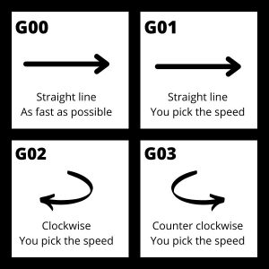
The G codes for movement are:
- G00 – Rapid travel
- G01 – Straight line movement (linear interpolation)
- G02 – Circular movement clockwise (circular interpolation clockwise)
- G03 – Circular movement counterclockwise (circular interpolation counterclockwise)
G00 is used for quickly moving the machine around when not cutting. The machine will move at the max allowed speed. This helps reduce the time it takes to run a program.
G01 through G03 are for cutting movements. They will move at the most recently listed feedrate specified with the F code.
Unit Modes
There are two unit modes that can be used when CNC machining.
G20 is used for working with imperial (inch) units and G21 is used for working with metric (mm) units.
You want to pay attention to your unit mode because 1 inch is 25.4 times bigger than 1mm so being in the wrong unit mode could be disastrous!
Positioning Modes
There are two types of positioning that can be used by the CNC.
Absolute positioning with G90 treats every new location that the machine reads as a location relative to a fixed point in the machine.
Incremental positioning using G91 reads every new location as a distance from its current location. Every time the machine moves to a new location in incremental mode, the new location becomes the new zero location.
The main body of most CNC programs is written in absolute positioning mode and smaller sections of the program are often written in incremental positioning mode.
Incremental positioning is usually used for repetitive features such as drilling a number of holes.
The pictures below show how the locations given to the machine differ between the two positioning modes. The numbers in parentheses ( ) are the coordinates that the CNC is given for each new move.


Compensation Modes and Offsets
Offsets and compensation modes allow the CNC machine to be more flexible. Using them allows you to use the same program with multiple machines as well as different cutting tools.
Offsets and compensation modes also make CNC programs easier to read and understand.
Tool Length Compensation
Tool length compensation is how the CNC machine accounts for the length of the cutting tool.
G43 turns tool length compensation on and G49 turns it off. G44 also turns tool length compensations on, but it is almost never used.
Using tool length compensation allows you to tell the CNC machine how long your cutter is. This lets you use the same program across multiple different tools. Each tool will have its own adjustment, or offset value, stored in the machine’s memory.
Tool length compensation uses H offset values stored in the machine.
H offsets are selected using the H code.

Cutter Compensation
Just like tool length compensation adjusts for the length of the cutting tool, cutter compensation adjusts for the diameter of the cutter.
If cutter compensation is off with G40 then the machine will move the center of the cutting tool along the path in the CNC program.
If cutter comp is on with either G41 – left compensation, or G42 right compensation then the machine will adjust the location so that the edge of the cutter follows the path given in the CNC program.
Like tool length compensation, this allows multiple different cutters to be used with the same program. Without cutter compensation, the program would need to be rewritten each time you wanted to use a new tool.
Cutter compensation is in the XY direction and tool length compensation is in the Z direction.
Cutter compensation uses D offset values stored in the CNC controller.
D offsets are selected using the D code.

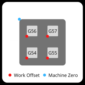
Work Offsets
While tool length and cutter compensation modes adjust for the cutting tool, work offsets adjust for the CNC machine itself in the program.
There are many different sized CNC machines available. Because machines vary in size, the location within the machine for a part can change.
Using a work offset such as G54 allows you to set a zero location for the program. This allows a much simpler and easier to read program. Also, work offsets let you use the same program in different machines.
Without work offsets you would need to write a new program for each CNC machine you want to run it on.
Most CNC machines have multiple work offsets available. G54-G59 are the most common.
Using multiple work offsets can be used to run more than one part at a time. The zero location gets switched and the same program is run again.
Multiple work offsets can even be used in a single program.
Canned Cycles
Canned cycles are a single code that allows you to perform common, repetitive machining functions such as tapping or peck drilling.
For example, peck drilling involves drilling into the part, backing up, drilling deeper, backing up again and repeat.
Using canned cycles allows you to have a simple, easy to read line code that gives the machine instructions for what can be a long process.

Using canned cycles can change the length of your program by a large amount. Smaller programs are usually easier to read and programs that are easier to read are usually easier to troubleshoot as well.
Next Steps
That covers the most common G codes, but what about the other letter codes?
Once you’ve mastered the G codes listed above, dive into the list of M codes.
There are a lot less M codes that get used and almost all of them are essential to know.
After that, check out the Complete List of CNC Letter Codes. You will likely know some of the common ones such as F for setting feed rates or S for setting spindle speeds through learning about the various G & M codes.
Our complete list of codes rounds them all up and puts them all in one place to make learning easy.
Check out our comprehensive CNC G code training:
Ready to master CNC programming?
Try the free 30 minute intro course to see how simple and easy G code can be. Take the shortcut to becoming a G Code Master today!