G02 tells your CNC machine to move in a clockwise circle. It follows a path along a set radius — like tracing the edge of a coin — while cutting at a controlled speed.
Any time you need to cut a curved path going clockwise, G02 is the code you’ll use.
Key Takeaways
- G02 moves the tool in a clockwise arc — use G03 for counterclockwise
- Requires an endpoint (X/Y) and a radius (R) or center offsets (I/J) to define the arc
- It’s a modal code — it stays on until you switch to G00, G01, or G03
- G02 and G2 are the same thing — the zero is optional
| G02 – At A Glance | |
|---|---|
| Function | Clockwise circular interpolation |
| Format | G02 X__ Y__ R__ F__ or G02 X__ Y__ I__ J__ F__ |
| Type | Modal (Group 1 – Motion) |
| Cancelled by | G00, G01, G03 |
| Required params | Endpoint (X/Y) + R or I/J |
What Does G02 Do?
G02 moves the cutting tool along a clockwise arc from one point to another. You give it an endpoint and a radius, and it figures out the curved path between the two.
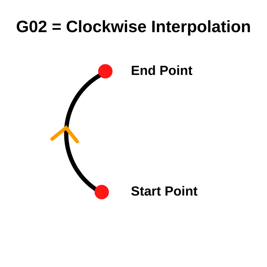
The machine doesn’t move in a perfect circle. It actually takes a series of very small straight steps that add up to look like a curve. This is called interpolation.

To use G02, you need three things:
- An endpoint — where the arc stops (X and Y coordinates)
- A radius — how big the arc is (R), or center offsets (I and J)
- A feed rate — how fast the tool moves (F)
G02 is a modal code. That means it stays active until you turn it off with another movement code like G00, G01, or G03.machine stays in clockwise arc mode until you switch to G00, G01, or G03.
G02 Format
The most common format uses the R word to set the radius:
G02 X__ Y__ R__ F__You can also use I and J instead of R. I and J define the center of the arc as an offset from your starting point:
G02 X__ Y__ I__ J__ F__Start with the R format — it’s easier to understand. Use I and J when you need to cut a full circle or an arc larger than 180°.
G02 Code Example
O0100 (Program number)
G90 G54 G17 G21 (Absolute mode, work offset, XY plane, metric)
G00 X0. Y-25. (Rapid to arc start point)
M03 S1200 (Spindle on CW at 1200 RPM)
G43 H01 Z5. (Tool length comp, move to clearance height)
G01 Z-5. F100. (Feed down to depth)
G02 X25. Y0. R25. F200. (Clockwise arc: 90° cut, 25mm radius)
G00 Z50. (Rapid to safe height)
M05 (Spindle off)
M30 (End program)
The tool starts at X0, Y-25. It cuts a clockwise arc to X25, Y0 — a 90° curve with a 25mm radius. The radius in the R word matches the distance from the start point to the center of the arc.
COMMON MISTAKE – Using a Negative R Value
A negative R value tells the machine to take the long way around the arc — more than 180°. A positive R takes the short route. Mix them up and the tool goes the wrong way, or cuts into your part.
Check your arc in simulation before you run it to make sure you got it right.
G02 vs G03
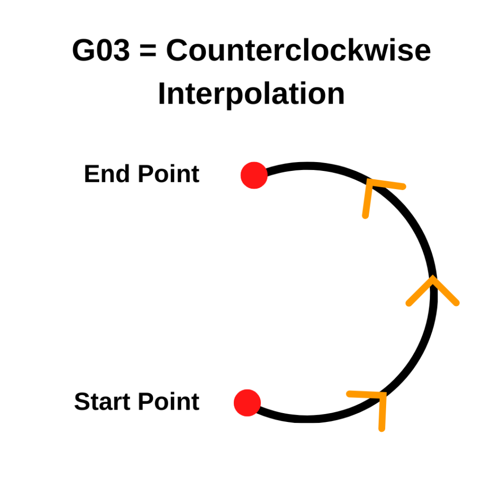
G02 and G03 work the same way. The only difference is direction. G02 goes clockwise. G03 goes counterclockwise. Both are viewed from above, looking down at the XY plane.
Which one you need depends on the shape of the part. Outside corners often use G02. Inside corners might use G03. CAM software picks the right one for you automatically — but if you’re writing code by hand, think through the direction before you write it.
G2 vs G02 — Does the Zero Matter?
No. G2 and G02 do the exact same thing. The leading zero doesn’t change anything.
Textbooks and formal references tend to use G02 while many programmers will use G2 to save a keystroke. If your shop has a standard, follow it — otherwise use whichever you prefer.
When to Use G02
Use G02 any time you need to cut a clockwise arc or radius. Common situations:
- Rounding an outside corner on a part
- Cutting a full or partial circular profile
- Blending a smooth radius between two straight cuts
- Milling around a curved feature
In a real program, G02 usually comes after the tool is positioned, the length offset is applied (G43), and the tool has fed down to depth with G01.
Things to Check Before You Run G02
Units
Know whether you’re working in inches or millimeters. G20 sets inches, G21 sets millimeters.
A 25mm arc run in inches mode will move 25 inches — not what you want.
Absolute vs. Incremental Mode
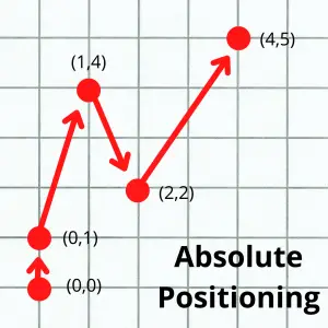
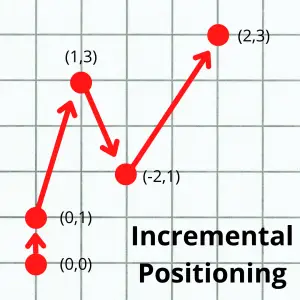
How the controller interprets your coordinates depends on whether you’re in G90 (absolute) or G91 (incremental) mode.
- Absolute (G90): coordinates are measured from the program zero.
- Incremental (G91): coordinates are measured from the current position.
The images below show the difference between the absolute and incremental positioning modes. The numbers in parentheses are the locations given to the the machine to make the move.
Start and Stop Positions
Think through the full path the tool takes — not just the arc itself. Where is the tool starting? Where does it end up? Is there anything in between, like a clamp or vise jaw? It’s easy to forget about fixturing and end up crashing into it.
How to Cancel G02
There’s no specific cancel code for G02. Just switch to any other movement code:
- G00 – Rapid travel
- G01 – Straight-line feed move (Linear interpolation)
- G03 – Counterclockwise arc (Circular interpolation CCW)
The new code takes over on that line and G02 turns off.
Codes Used With G02
You’ll rarely see G02 by itself. Here’s what usually goes with it:
- G17/G18/G19 – Sets the cutting plane (XY, XZ, or YZ). Most mills default to G17 (XY).
- M03 – Spindle on, clockwise
- M08 – Flood coolant on
- M09 – Coolant off
- N – Program line number
- R – Radius size
- S – Set spindle speed
- X – X axis location
- Y – Y axis location
FAQS
What is the difference between G02 and G03?
G02 moves clockwise. G03 moves counterclockwise. Both use the same format — endpoint plus radius or I/J plus feed rate. The direction is the only difference.
Can I cut a full circle with G02?
Yes. Set your start and end point to the same location, then use I and J to define the center. You don’t need an X/Y endpoint when the arc starts and ends at the same spot.
When should I use I/J instead of R?
Use I/J for full circles and arcs over 180°. The R method can confuse some controls on large arcs. I/J is always explicit about where the center is.