The F code sets the feedrate — how fast the cutting tool moves through the material. It’s one of the most important values in any CNC program. Set it too slow and you waste time. Set it too high and you break tools.
Key Takeaways
- F sets the cutting speed (feedrate) for moves made with G01, G02, G03, and most canned cycles
- G00 (rapid) ignores the F value entirely — the machine always rapids at max speed
- Two feedrate modes exist: per minute (in/min or mm/min) and per revolution (in/rev or mm/rev)
- Mills typically run in per-minute mode (G94); lathes more often use per-revolution mode (G99)
- Feedrate stays active until you change it — it’s a modal command
| F Code – At A Glance | |
|---|---|
| Function | Sets the cutting feedrate |
| Format | F[value] — example: F15.0 or F0.008 |
| Type | Modal (stays active until changed) |
| Used with | G01, G02, G03, canned cycles |
| Ignored by | G00 (rapid travel) |
| Unit modes (mill) | G94 = per minute, G95 = per revolution |
| Unit modes (lathe) | G98 = per minute, G99 = per revolution |
What Does the F Code Do?
The F code tells the machine how fast to move the cutting tool when making a cut. It works with any motion code that cuts material — linear moves (G01), arcs (G02/G03), and drilling cycles.
One thing to know right away: G00 ignores the feedrate. Rapid moves always run at the machine’s maximum speed, no matter what F value was last programmed.
F Code Format
The basic format is just the letter F followed by a number:
F15.0Decimal points are allowed. The number of decimal places depends on the unit mode your machine is running.
- Inch, per minute: one decimal place — example: F12.5
- Metric, per minute: one decimal place — example: F200.0
- Inch, per revolution: four decimal places — example: F0.0846
- Metric, per revolution: three decimal places — example: F0.329
Feedrate Modes: Per Minute vs. Per Revolution
Per Minute (mm/min or in/min)
This mode sets how far the tool travels in one minute. It does not depend on spindle speed — if the spindle slows down, the feed rate stays the same.
This mode is standard on most mills. It’s activated with G94 on mills and G98 on lathes.
Per Revolution (mm/rev or in/rev)
This mode sets how far the tool moves per spindle rotation. As the spindle speeds up or slows down, the feed automatically adjusts to keep chip load consistent.
This mode is common on lathes. It’s activated with G95 on mills and G99 on lathes.
Most lathes switch between these modes regularly depending on the operation. Most mills stay in per-minute mode.
COMMON MISTAKE – Forgetting that G98 and G99 mean something different on lathes vs. mills
On a mill, G98 is a canned cycle return mode (initial point). On a lathe, G98 sets feedrate per minute. Copying code between machine types without checking this will cause problems.
F Code in a Real Program
Here’s what F looks like in context on a mill program:
G90 G54 G00 X1.0 Y0.5      (Rapid to start position)
G43 H01 Z0.1               (Tool length offset, move to clearance)
G01 Z-0.25 F5.0            (Feed down to depth at 5 in/min)
G01 X3.0 F15.0             (Feed across at 15 in/min)
G00 Z1.0                   (Rapid back to clearance — F ignored)
What Factors Affect the Right Feedrate?
There’s no single correct feedrate — it depends on your specific setup. Here are the main factors:
Cutting Tool
- Sharpness: A dull tool requires slower feeds to avoid breaking
- Size: Larger tools can generally handle higher feeds than small diameter tools
- Material: Carbide tools run faster than high-speed steel (HSS). Ceramic tools can run faster still
Workpiece Material
Softer materials like aluminum, brass, and plastic allow much higher feedrates than tough materials like stainless steel or titanium. Start conservative with any new material.
Spindle Speed
Feedrate and spindle speed work together. “Speeds and feeds” are paired for a reason — they both affect chip load, heat, and tool life.
Depth and Width of Cut
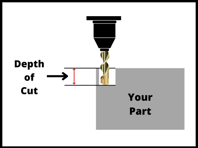
Deeper or wider cuts put more force on the tool. When you increase depth or width, you typically need to slow the feed down to compensate.
Coolant

Flood coolant reduces heat and can allow higher feedrates. Running dry often means cutting slower.
Machine Condition

Worn or loose machines may need slower feeds to hold tolerance and avoid vibration. A newer, rigid machine handles higher feeds better.
How to Calculate Feedrate
Milling Feedrate (per minute)
The standard formula for milling feed rate is:
Feed Rate (in/min) = RPM × Number of Flutes × Chip Load- RPM = spindle speed in revolutions per minute
- Number of flutes = number of cutting edges on the tool
- Chip load = how thick each chip should be (get this from your tool manufacturer’s chart)
Example: 4-flute end mill, RPM = 2000, chip load = 0.004 in/tooth
Feed Rate = 2000 × 4 × 0.004 = 32.0 in/minProgram that as: F32.0
Converting Between Per Minute and Per Revolution
Feed per revolution = Feed per minute ÷ RPM
Feed per minute = Feed per revolution × RPM
Example: F200.0 mm/min at 1000 RPM = 200 ÷ 1000 = 0.200 mm/rev
COMMON MISTAKE – Too aggressive chip load for a long tool
A long tool deflects more than a short one. The same chip load that works fine on a short end mill can cause chatter, poor finish, or breakage on a long reach tool.
When sticking out more than 3× the tool diameter, reduce your feed rate.
How to Choose a Starting Feedrate
Most machinists start with manufacturer specs — the tool data sheet or catalog will give you recommended chip loads and speeds for different materials. Use those as your starting point, then adjust from there.
Good starting resources:
- Tool manufacturer charts (Kennametal, Sandvik, OSG, etc.)
- Machinery’s Handbook
- CAM software (most calculate feeds and speeds automatically)
- Online feeds and speeds calculators (FSWizard, G-Wizard, etc.)
General guidelines:
- Carbide tools can run faster than HSS — in some cases 3–5× faster
- Harder workpiece materials need slower feeds
- Slower feeds = longer tool life, less heat, better finish
- Most manufacturers give a range — start at the low end and work up
Feedrate Override
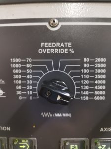
The feedrate override knob on the machine control panel lets the operator adjust the programmed feedrate on the fly — anywhere from 0% to 200% of the programmed value.
This is useful when running a new program for the first time. Set the override to 50% and gradually increase it as you gain confidence in the program.
COMMON MISTAKE – Forgetting about your feedrate override
Why it matters: The next operator (or you, later) assumes the machine is running at programmed speed.
Cycle times will be off, and the parts may not be cut correctly if feeds are intentionally matched to spindle speeds.
FAQs
What does the F code control in CNC?
The F code controls the feedrate — the speed at which the cutting tool moves through the material during a cut. It applies to G01 linear moves, G02/G03 arc moves, and most canned cycle operations.
Does G00 use the F code?
No. G00 (rapid positioning) always moves at the machine’s maximum speed regardless of the F value. The feedrate is only active during cutting moves.
What’s the difference between feed per minute and feed per revolution?
Feed per minute sets how far the tool moves in 60 seconds, independent of spindle speed. Feed per revolution sets how far the tool moves per spindle rotation, so it automatically adjusts if the spindle speed changes. Lathes commonly use per-revolution mode (G99); mills typically use per-minute mode (G94).
How do I know what feedrate to use?
Start with the tool manufacturer’s recommended chip load for your material. Multiply chip load × number of flutes × RPM to get your starting feed per minute. Adjust based on machine rigidity, tool stickout, and cut depth.