Table of Contents
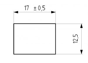
ToggleThe definition of a tolerance block is a section on an engineering drawing or blueprint that identifies tolerances for a dimension that aren’t specifically called out on the print. Notice how the 17.5 dimension below has a tolerance directly associated with it.
Now look at the 12.5 dimension and notice that no tolerance is specified. Because there is no tolerance called out, the tolerance in a tolerance block (general tolerances) would be applied to this specific dimension.
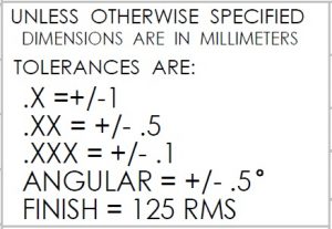
Note: The contents of the tolerance block are often referred to as the general tolerances. Depending on the units used on the blueprint, the tolerance block can be specified in metric or imperial (inch) units.
Most tolerance blocks are identified based on the number of decimal places of the feature on the blueprint.
Using our previous examples again, notice that the 12.5 dimension has one number after the decimal place. Based on the tolerance block, this would assign the +/- 1 mm tolerance to the dimension.
If the dimension was instead 12.54 then the tolerance assigned would be +/- .5mm. Angular dimensions often are specified in the same way. In our example, all unspecified angular tolerances would be assigned the =/- .5° tolerance.
GD&T is a complicated subject and understanding it correctly can be the difference between a perfect part and scrap.
The best way to learn GD&T is from experienced teachers who can break down the material into manageable pieces.
Luckily, we know someone.
And MachinistGuides.com readers get an exclusive discount on training!
For more information see these related articles:
© 2025 Machinist Guides