Table of Contents
ToggleWhat does typical mean on a blueprint?
Typical on an engineering drawing identifies a repeated feature. This is identical to a feature which is identified as 2x or 5x.
A typical dimension callout will occasionally be followed by a 2x, 5x or similar, to specify the quantity of features which are tolerance the same.
The typical callout will most often be used as part of a repeating pattern such as a bolt hole circle, to identify the hole sizes or angle between the holes.
Another common application is to identify a common chamfer size on a component. It should be noted that the notation of “typical” is not a part of the current revision of the ASME Y14.5 standard and therefore not a recommended notation for use on an engineering drawing. There are however countless blueprints in the wild which may already use this language.
What is the symbol for a typical dimension?
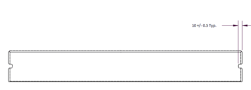
There is no GD&T symbol for a typical dimension. A typical dimension callout is identified with either TYP. or TYPICAL. In the example below, the typical notation is used to reference that the slot on both sides of the part is to be machined to the same depth.
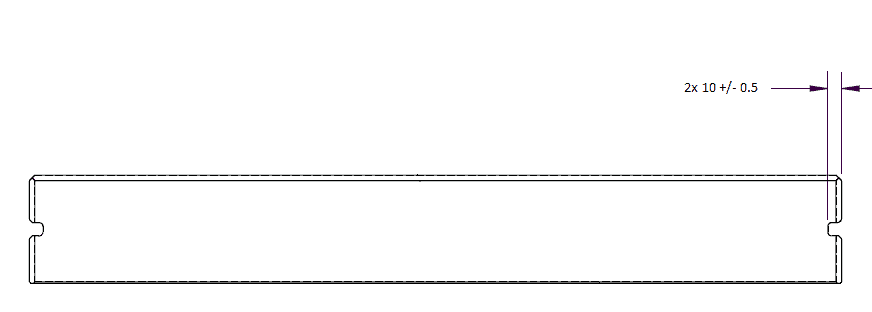
A better way to identify the same dimension would be as shown below. It is best to not leave anything to the imagination of the person interpreting the blueprint.
Want to learn more?
GD&T is a complicated subject and understanding it correctly can be the difference between a perfect part and scrap.
The best way to learn GD&T is from experienced teachers who can break down the material into manageable pieces.
Luckily, we know someone.
And MachinistGuides.com readers get an exclusive discount on training!
Related Articles
For more information see these related articles: