What is a chamfer?
A chamfer is an angle on the edge of a workpiece.
They are created for mainly for protecting the chamfered object as well as anyone who might come in contact with the object.
The edge can be the outside of the part, where a hole breaks through a surface or where any two surfaces meet.
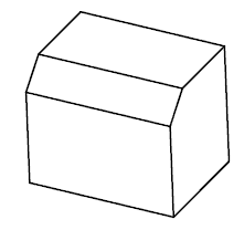
Notice the chamfered edges in the picture above.
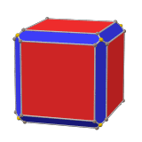
The cube above has chamfered corners where all the main faces intersect.
Chamfering those intersections reduces the sharpness of, or softens the corners.
Types of chamfers
Leg length chamfers
The most common way to spec a chamfer is by giving its leg length size and the chamfer angle.
In the picture of a triangle below, the legs are the a and b sides of the triangle.

If no angle is given, the chamfer angle would be assumed to be 45 degrees. This can be a dangerous assumption though. It is always best to confirm the chamfer angle when not directly specified.
Face width chamfers
Occasionally, a chamfer will be specified as being measured as a face width. This can be seen abbreviated as F.W. on some blueprints.
In the picture below, the leg length of the chamfer would be the length of the a and b sides. These would be equal in a 45 degree chamfer. The length of the c side would be the face width of the chamfer.
If a chamfer is called out as a face width, then it is to be measured along the hypotenuse of the chamfer.
To convert a leg length dimension to face width simply multiply the leg length value by 1.414. To convert from a face width dimension to a leg length dimension, reverse the process and divide by 1.414.
It should be noted that these conversion factors only work if the chamfer is at 45 degrees (the most common chamfer angle). If you need to calculate the face width of a chamfer at a different angle use a triangle calculator.
Chamfers compared to similar features
Chamfer vs bevel
A chamfer and a bevel are the same, especially in the case of machining.
Some will debate this point and argue that a chamfer takes the sharp corner off the part and that a bevel would do the same but all the way to the opposite side surface.
While there are some diagrams available online that will show this as true, this is incorrect. Merriam-Webster clearly defines a chamfer and bevel as the same thing.
Chamfer vs break edge
Chamfers are often left as an afterthought for blueprint drafters.
Many times they have no functional requirement but are merely added to protect the part and anyone who might come into contact with it from damage. Deburring an edge is very similar.
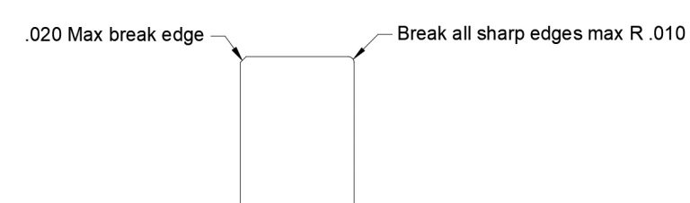
In cases where the requirements are not strict, you will often see a break edge or break all edges requirement listed.
This means the sharp edge should be removed from part, but it is not directly controlled. In cases where a break edge is specified, the drafter is generally looking for a chamfer size of .010″-.020″ and sometimes even less.
Break edge callouts will rarely be identified with an angle associated with them.
Chamfer vs countersink

Countersinks are chamfers applied to a round feature such as a hole.
The main difference between chamfers and countersinks is that chamfers are usually specified at 45 degrees and countersinks have a larger variety of common angles.
Countersink angles are also specified as the angle between two opposite sides of the feature. This results in the angle spec being doubled. A 45 degree chamfer would often be listed as a 90 degree countersink. Common countersink angles are 82, 90, 100 and 120 degrees.
Chamfer vs deburr
As I noted above, a deburr callout is very similar to a break edge. Deburring is the act of removing a sharp edge and often raised edges along the feature.
Tiny bits of raised metal can be quite dangerous. Deburring will remove these sharp bits. Similar to break edges, deburr callouts are usually pretty loosey goosey.
Chamfer vs fillet
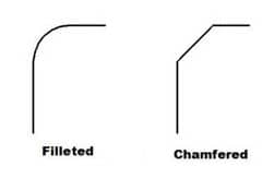
A fillet is a rounded or radiused corner and a chamfer is a straight cut. Notice the difference in the picture above.
Chamfers do not have to be a 45 degree angle as shown in the picture above, but this is certainly the most common configuration.
How to specify chamfer dimensions
Dimensioning chamfers is done with a call out that specifies the length of the chamfer along with the angle of the chamfer. If no angle is given the chamfer is assumed to be at 45 degrees.
Chamfers can also be specified by giving both legs of the chamfer such as:
Chamfer all edges .025″ x .025″
Chamfer notation example #1
If the example above read “Chamfer all edges and corners .030”, the callout would be the same as it is written currently. Angles other than 45 degrees are used, but are much less frequent.
Chamfers are often specified in the notes of a blueprint such as in the example above.
Chamfer notation example #2
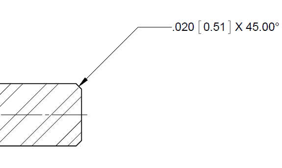
In this example, the chamfer would have a leg length of .020″ and a chamfer angle of 45.00 degrees.
Measuring chamfers
How to measure the size of a chamfer
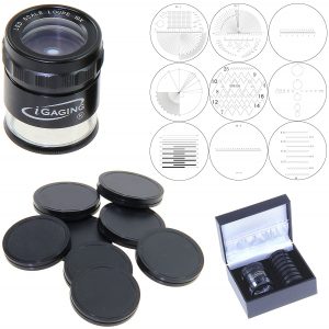
A chamfer length or depth can be measured utilizing many different pieces of measuring equipment. Optical comparators and CMMs are often used in industry, but if you are reading this you will likely want to measure your chamfer with a gauge called a pocket comparator, often referred to as an eye loupe.
The pocket comparator uses a magnifying lens and reticle to enable the user to measure the size of the chamfer.
How to measure the angle of a chamfer
Chamfer angles are often assumed to be the same angle as the tool used to generate them. The most common chamfer angle is 45 degrees.
Depending on the part geometry, different tools can be used to measure a chamfer’s angle. The angle can be calculated using the triangle calculator referenced above or a protractor can be used.
Want to learn more?
GD&T is a complicated subject and understanding it correctly can be the difference between a perfect part and scrap.
The best way to learn GD&T is from experienced teachers who can break down the material into manageable pieces.
Luckily, we know someone.
And MachinistGuides.com readers get an exclusive discount on training!
Related Articles
For more information see these related articles:
