Whether you are a seasoned machinist or a machine operator starting a new career, a good book can go a long way towards developing your understanding of the parts, pieces and processes involved in the machining trade.
We have laid out our recommendations for all skill levels and even included some quality choices for topics such as CAD and GD&T.
Check out Machinist Guides picks for best machining and CNC related books!
Best Beginner Machining Book
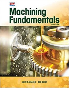
Machining Fundamentals
It’s not quite machining for dummies, but this text is easily the most beginner friendly book while also going in depth on the subject.
If you take a beginner machining course, this is likely the textbook that will be used. It covers everything from manual machining to CNC and everything in between. This textbook does a good job of not assuming you have previous knowledge and instead teaches all the basics and then some in an easy-to-understand format.
One of the best things about this title is that there are a lot of pictures to show you what is being taught. There is no better beginner’s book for machining. If you are looking for something that is primarily focused on CNC machining then look for one of the books listed below instead.
Best Beginner CNC Book
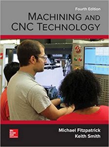
Machining and CNC Technology
Machining and CNC Technology is a great overall machining book similar to our Best Beginner Machining Book.
Where this book excels is in providing an excellent introduction to CNC related topics. Too often the actual operation and setup of the machine are not given enough coverage.
This book gives a great introduction to CNC machining and covers everything from machine setup to program planning and g code tutorials.
Machining and CNC Technology is another textbook that is so thorough it is often used for training in machine tool classes.
Best CNC Programming Book
CNC Programming Handbook
Not a book for beginners. The CNC Programming Handbook by Peter Smid goes in depth on just about every CNC programming related topic.
Everything is covered and in great detail. Personally, this isn’t the type of text I would read straight through. Instead, I recommend using it like a CNC version of the Machinery’s Handbook.
This is absolute CNC reference grade material.
The CNC Programming Handbook makes a great comprehensive desk reference. When it comes to learning CNC programming, if this book doesn’t have it then most likely no book does.
You won’t need it on a daily basis but when you come across a topic that you don’t understand, it will be an invaluable resource.
Best Beginner GD&T Book
2018 Ultimate GD&T Pocket Guide
GD&T can be a complex topic to learn. Our best GD&T book recommendation is 488 pages! That’s a lot of information to take in.
Luckily, there are many different “pocket guides” out there that condense it down to a beginner level so you can comprehend the basics.
This pocket guide does a good job of covering the most common applications of GD&T and it’s likely that unless you are working in inspection, it will cover everything that you need.
Even experienced inspectors can benefit from having a quick reference handy.
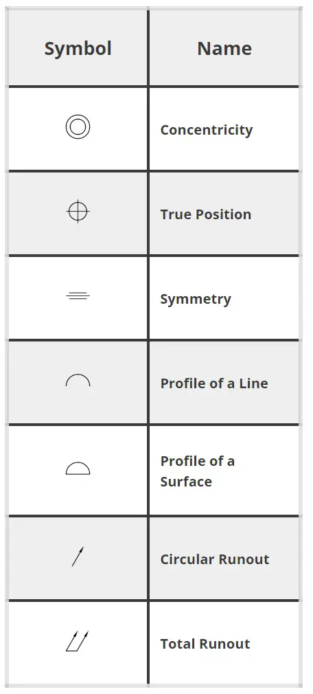
Best Geometric Dimensioning and Tolerancing (GD&T) Book
GD&T: Application and Interpretation
Geometric dimensioning and tolerancing can be a difficult subject to tackle. Fortunately, this book by Bruce Wilson does a great job of breaking it down into smaller pieces.
In my opinion, when it comes it GD&T related matters, a picture says a thousand words. Luckily this book contains countless examples to make understanding some of the more difficult concepts of GD&T much simpler.
One item worth noting is that this book is based on the ASME Y14.5 2018 revision. This is the most recent revision of the drawing standard and many other textbooks available are based on older revisions of the standard. For reference, 2009 was the previous revision of ASME Y14.5.
Note: If your shop doesn’t have a copy (which they should), more experienced GD&T users may want to consider a copy of the ASME Y14.5-2018 standard to have around for reference as well.
Best Overall Machinist Reference Book
Machinery’s Handbook
This is the book by which all other references are judged. Machinery’s Handbook, which is often referred to as the Machinist Handbook, is the quintessential reference for all machining.
This is not a book for beginners, but instead for someone who already has some knowledge of machining. Every machine shop should and likely already does have a copy or two laying around. Each new edition continues to add new and relevant content to an already extensive collection of important information.
Don’t be afraid to pick up a previous edition if you can find it used or cheaper. The difference between one edition isn’t that great. Just avoid a copy that is five or ten editions out of date.
Every machinist should have a copy of this book available to them.
Best Beginner CAD Book
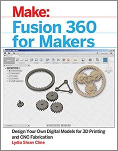
Fusion 360 for Makers
If you are just getting started with CAD, then in all likelihood you will be working with Fusion 360. Fusion 360 is a free (for personal use) piece of CAD software from Autodesk, makers of Inventor. Inventor is one of the most popular pieces of drafting software used in machine shops around the world.
Learning Fusion 360 will teach you skills which will transfer to other more advanced pieces of software. Although, I should point out that Fusion 360 is no slouch and will allow you to create some pretty advanced widgets and doodads if you take the time to learn it.
Fusion 360 for Makers is a great starting point for newbies to learn the basics and get acquainted with the software.
Best Budget Beginner Book for Lathes
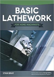
Basic Lathework for Home Machinists
If you are just getting started with lathes and are looking for a guide to start you off cheap then this is the book. It is not the most comprehensive, but it does a good job laying things out for beginners.
The abundance of pictures helps machining newbies wrap their head around the parts and processes involved with metal lathes. The only complaint would be that the pictures are in black and white which makes it a little bit harder to see some of the finer details in the photos.
If you aren’t ready to dive into a literal textbook yet, then this book can get you started at a budget friendly price.
Best Budget Beginner Book for Mills
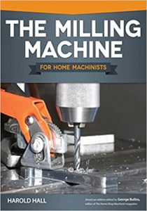
The Milling Machine for Home Machinists
Just like Basic Lathework for Home Machinists, this book is a good starter book.
One area where The Milling Machine for Home Machinists excels is the color pictures. There are a lot of them and they make it easier to understand the topics being covered.
This is not the book you want if you have been running a mill for any length of time. It covers entry level material only. Once you fully understand the information covered, think about stepping up to one of the more comprehensive machining books for beginners such as Machining Fundamentals or Machining and CNC Technology.
Conclusion
Thanks for checking out our guide to the best machining and CNC books. Hopefully they help add to your physical and mental library.
P.S. If you have a good recommendation for a machining book please share it in the comments below.
Related articles
For more information check out these related articles: