S CNC Code Explained: An Easy Intro for Beginners [Spindle Speed]

What is the S CNC code used for?

The S code is used together with a number value to set the speed of the spindle on a CNC machine.

The number value can have up to four digits and cannot have a decimal point. 100.5 is not an acceptable value to use when setting the spindle speed. 100 or 101 would be acceptable alternatives.

The number value is in revolutions per minute (RPM).

For example, to set the machines spindle to 3000 RPM use “S3000”.

The majority of machines will allow four digits to be used to set the spindle RPM. So anything from 1 to 9,999 RPM. Some machines will allow five digits which allows them to go from 1 to 99,999 RPM

The required spindle speed will vary and can be higher or lower depending on the material of the workpiece, surface finish requirements and the limitations of the CNC machine itself.

When to use the S code?

S codes show up in CNC programs at many locations including at the beginning of the program, after setting the spindle rotation direction (clockwise/counterclockwise) and also whenever there is a change of material, surface, or tool.

Setting the spindle speed at the start of each new section of the program ensures that the spindle is running at the correct RPM if part of the program needs to be rerun for any reason.

Ready to master CNC programming?

Try the free 30 minute intro course to see how simple and easy G code can be. Take the shortcut to becoming a G Code Master today!

Types of spindle control

The spindle is a very important part of any CNC machine. It doesn’t matter if you are working with a mill or a lathe.

Almost everything you do with your CNC will involve the spindle in some way or another.

Below are the types of control that you have over the spindle and some of it’s related functions as well as the codes they use.

Direction of rotation – M03 & M04
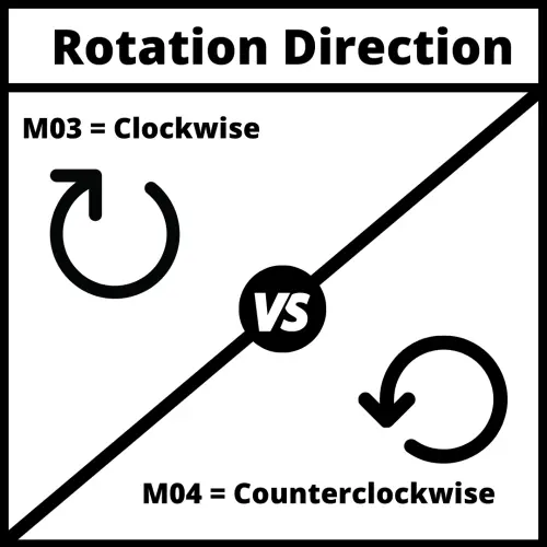
Spindle direction

The direction of rotation of the spindle can be set in the CNC program by using either the M03 code (clockwise rotation) or the M04 code (counterclockwise rotation).

Using either of these codes turns the spindle on in the direction chosen.

Most machines use tooling that requires using clockwise rotation of the spindle (M03).

Spindle stop – M05

The M05 code is used to stop the spindle.

M05 is normally used when there is a tool change or at the start of a new section of the program.

The spindle will also stop after the tool goes to the home position at the end of the program when using the M30 code.

The emergency stop button can also be used to stop the spindle in the case of emergencies.

Speed

There are two types of speed control for a CNC spindle. 

CNC mills mainly work in RPMS and you usually will not need to specify this in your program.

CNC lathes on the other hand use G96 and G97 to switch between the two speed modes.

Revolutions per minute – G97

Using this spindle speed mode, the spindle will turn at a constant rate as specified by the S code.

For example if you set the speed with S5000, the machine spindle will rotate at 5,000 RPMs until it is changed with another S code or the spindle is stopped using the M05 code.

Constant surface speed – G96

The other spindle speed mode is constant surface speed using the G96 command.

This code instructs the machine to maintain a constant cutting speed at the tip of the tool.

A smaller diameter workpiece will need to spin faster to maintain the same surface speed as a larger part.

The picture below shows how if both parts make one revolution, then the larger part will have traveled faster because it needs to cover a larger distance in the same amount of time.
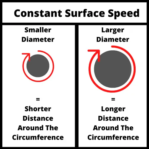
illustration that shows the difference between the cutting speed of a smaller and larger diameter for cutting speed

Using the constant surface speed mode will cause the machine to change the RPMs of the spindle as the size of the part changes so that the cutting speed is constant.

This way of programming can provide a better surface finish and extend tool life.

Spindle orientation – M19

The M19 command is used to precisely load a tool into the spindle. 

This is more critical with certain canned cycles such as boring.

Tool change – M06

Most machining centers allow the swapping of tools in and out of an automatic tool changer.

Automatic tool changers increase the productivity of the machine by decreasing the amount of time needed to swap cutting tools.

Common codes used with the S command

Spindle speed vs cutting speed

Both spindle speed and cutting speed are commonly used together, but they mean different things.

The cutting speed given by the F code controls how fast the tool advances in a given machining process. The cutting speed controls the forward movement at which the tool will remove material while cutting.

Meanwhile, spindle speed (S code) is the number of turns the spindle can do in one minute (revolutions per minute). Both are really important factors to be aware of when you are programming.

Speeds and feeds. Take note because this will be referred to often.

Proper speeds and feeds prevent tool breakage and increase tool life while also allowing for a higher quality surface finish.  

How should you change your spindle speed based on the workpiece?

Small pieces usually require less speed than workpieces of big diameters.

However, it also depends on the process and the material you are machining.

If the material is very rigid, it is recommended to use a low spindle speed at first and low feed rates, later you use a higher spindle speed for an optimal end finish of the workpiece and higher feedrate.

Ready to master CNC programming?

Try the free 30 minute intro course to see how simple and easy G code can be. Take the shortcut to becoming a G Code Master today!
T CNC Code Explained: An Easy Intro for Beginners [Tool Selection]

What does the T CNC code do?

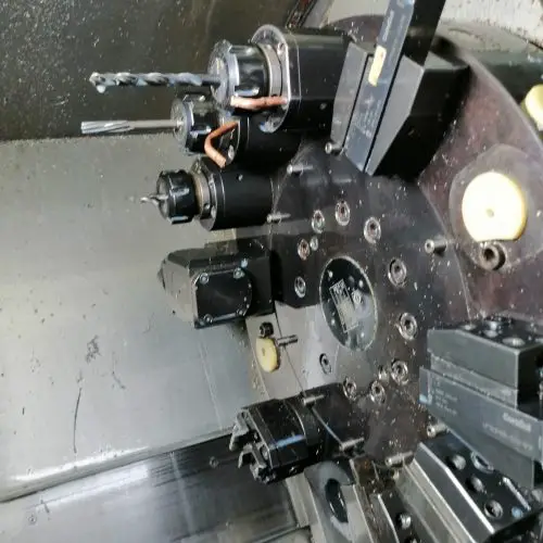
On most CNC machines, the T code tells the machine the tool to place in the tool changer to prepare it for a tool change.

The M06 command will then perform the tool change.

On some CNC machines, the T code will actually switch to the tool called out.

The T command is a very important CNC code because most programs will use multiple tools during the execution of a program.

It is not uncommon for dozens of tool changes to be performed in the process of running a more complex program.

When does the T code get used?

The T code is used at the start of a program to make sure the correct tool is loaded before any machining is performed.

After this initial setup, the T code is used every time the machine switches to a new tool.

If tool #1 is currently in the CNC spindle, calling tool #2 with the T02 command will ready it in the tool changer. Using the M06 command will swap tools.

Readying the tool before the switch saves precious machining time, something that is more important for high volume production machining.

Even though the tool is already loaded in the tool changer, it is advised to still call the T02 command in this instance to make sure that the correct tool is loaded.

The code would look like this:

T02

<machining code here>

T02 M06

Again, this format is used to ensure that the correct tool is placed in the CNC spindle during the tool change.

Without using the T02 command right before the M06 tool change command, it is possible that another is loaded in the tool change position and will be swapped in.

Imagine if you needed to re-run a portion of the code and started your program after the initial T02 code. If you didn’t repeat the T02 code right before the tool change then the machine would use the last tool number from its memory.

There is a good chance that it isn’t swapping the correct tool which can mean a machine crash.

Ready to master CNC programming?

Try the free 30 minute intro course to see how simple and easy G code can be. Take the shortcut to becoming a G Code Master today!
How to change tools

CNC cutting tools are changed using the M06 command. On some machines (usually older CNCs), the T code will cause the machine to perform a tool change.

Check your machine manual to know how your machine will react.

If your machine is equipped with an automatic tool changer, then it is likely that you will be using the M06 command to change tools.

an automatic tool changer on a dmg mori cnc machine
Automatic tool changer carousel

Where should you document your tools?

Information about your tools should be stored in two locations, on your machine setup sheet and in your tool offset library.

The setup sheet is used to communicate to the machine operator what tools are expected to be loaded in the machine while running the program.

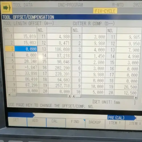
The tool offset library, sometimes called the tool offset table stores information related to the size of your cutting tools. This includes both the diameter (D offset) and tool length or height (H offset).

Offset Library
Offset library with H offsets on the left and D offsets on the right

The D offset and H offset values allow the machine to compensate for the size of the cutting tool and accurately machine the part.

Offsets and your cutting tools

Two of the most important characteristics of your cutting tools are their length and diameter. 

These two characteristics are stored as H (height) and D (diameter) offsets.

Knowing these two values and storing them in your offset library allows the machine to adjust for the size of the cutter when running the program. 

Without these adjustments using height (H) and diameter (D) offsets, the program would need to be rewritten for each new tool. Not the most efficient way to machine parts.

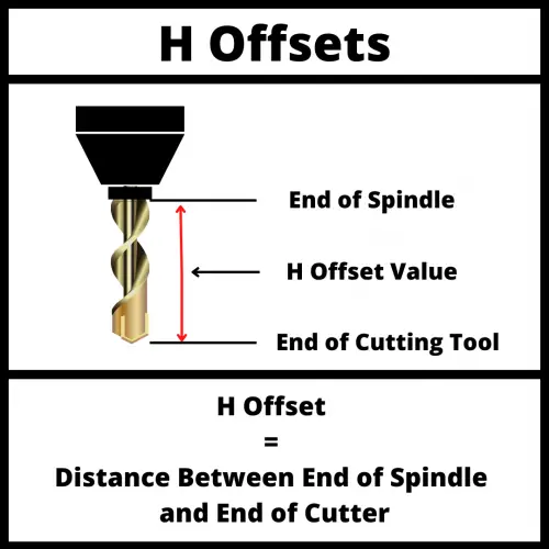
illustration of a cnc cutting tool that shows what an H offset is

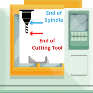
The value of the H offset is the distance between the end of the spindle and the end of the cutting tool.

The H code is used to select the H offset stored in the offset library when tool length compensation is turned on with the G43 code.

illustration of a cnc cutting tool that shows what an D offset is

The D code is used to choose the D offset to be used when cutter compensation is turned on with either the G41 – Cutter compensation left or G42 – Cutter compensation right codes are used.

The D offset value is a number stored in the offset library that tells the CNC the size (diameter) of the cutting tool. 

Once the machine knows the size of the cutter it can adjust how it runs the program based on that size.

Frequently asked questions about the T code

How is the T code used differently on mills vs lathes

As stated above, most CNC milling programs will use more than one tool to complete the machining of a workpiece.

Therefore, using the T code for tool changes is necessary.

On lathes, the T change is used less often because the same cutter can perform many turning operations.

However, operations such as parting-off, threading, and drilling require specific tools. The number of tools allowed on a CNC lathe depends on the number of cutters that fit in the machine’s turret.

What does T0X.0X mean?

You may see some codes that have two numbers separated by a dot along the T code (e.g. T01.01).

This formatting exists because some controllers such as Fanuc allow different offsets to be assigned to the same tool.

Depending on the type of operation performed by the tool, you may need to change its offset values. T01.01 is tool #1, offset 1. T01.02 would be tool #1, offset 2.

Ready to master CNC programming?

Try the free 30 minute intro course to see how simple and easy G code can be. Take the shortcut to becoming a G Code Master today!

X, Y, & Z CNC Codes Explained: An Easy Intro for Beginners [Coordinates]

What kind of coordinate system is used in CNC machining?

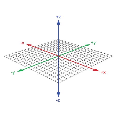
Almost every CNC machine uses a Cartesian coordinate system based on an X, Y, and Z-axis.

The coordinate system allows the machine to identify locations, move in specific directions and establish positions in a three-dimensional space.  

Coordinate systems are formed by the axes (X, Y & Z), planes, and an origin where the three axes meet. 

Using an X, Y or Z code in a CNC program tells the machine to go to a specific location along those axes. Location changes can be in one or more axes. 

If only a Z axis coordinate is given then the machine will only move in the Z axis. This is the same for the other axes as well.

XY Plane
The grid in the picture shows the XY plane. The XZ and YZ axes combine to make planes as well.

Ready to master CNC programming?

Try the free 30 minute intro course to see how simple and easy G code can be. Take the shortcut to becoming a G Code Master today!
Terms to know

To understand the coordinate system used by CNC machines, you need to first understand a few terms and concepts.

Coordinates

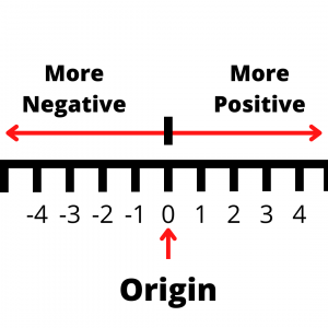
a number line that shows positive and negative numbers as well as the origin location

A coordinate is a location given in one or more axes.

Axis or plural axes

An axis is a straight line.

Along this straight line, each axis has a positive and a negative side.

The negative side continues on forever with larger and larger negative numbers. -1, -10, -99, -20,346 on til negative infinity.

On the other end of the axis are larger and larger positive numbers. 1, 5, 24, 578, 356,728 and on til positive infinity.

The two sides of the axis are separated by a center point.

At the center point the value of the axis is 0. This is called the origin.

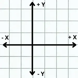
Where the X and Y axes cross is the XY origin

Origin

The origin is the zero location of one or more axes. 

Typically, when talking about origins we are referring to the zero location of multiple axes.

CNC mills are usually 3 axis machines and lathes are 2 axis. Both types of machines can have more axes but let’s keep things simple.

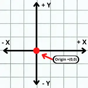
the X and Y axes shown on graph paper with the origin identified.

Less axes are usually easier to understand so let’s start with 2 axis coordinates.

With two axes, the origin would be the (0,0) location.

The is the location where the two straight line axes cross. This could be any two axes (XY, YZ, XZ) but generally we are referring to the X and Y axes. (0,0) is (X=0, Y=0).

Note that the two axes are perpendicular, or at 90 degrees to each other.

When talking about three axes, we are referring to the X, Y and Z axes.

When working with three dimensional coordinates, the origin is the spot where all three axes meet.

This is the (0,0,0) location.

Each of the axes are still perpendicular to each other. The order of axes is the same as before with the Z axis added on so (0,0,0) is (X=0, Y=0, Z=0).

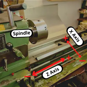
a lathe with the X and Z axis shown and the spindle identified
A 2 axis lathe
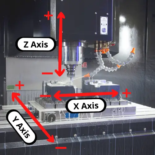
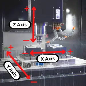
an illustration that shows the X, Y and Z axes on a CNC machine
A 3 axis mill

Plane

XY Plane

A plane is a two-dimensional flat surface. 

The most common one when talking about CNC machines is the XY plane. The XY plane is shown as the grid in the picture above.

The plane consists of all the possible coordinate location combinations possible in the X and Y axes.

There are three different types of plane combinations: XY, YZ, and XZ, and each plane has four quadrants with corresponding negative and positive values, two axes and an origin.

Quadrant

coordinates on a graph paper background that shows the different X and Y quadrants

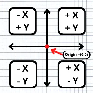
A quadrant is an area of the coordinate system plane. The four quadrants are shown below.

Quadrant 1 has positive X and positive Y values.

Quadrant 2 has negative X and positive Y values.

Quadrant 3 has negative X and negative Y values.

Quadrant 4 has positive X and negative Y values.

CNC machinists will want to pay attention to what happens when their machines switch quadrants. 

Often changing the direction of travel from one direction to another will result in small defects or unintended features on the workpiece depending on the quality of the CNC machine.

Understanding Cartesian coordinates on a CNC machine

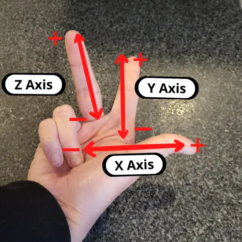
Usually, an easy way to understand the coordinate system for your CNC machine is to follow the Right-Hand Rule.

Hold your hand out palm up with your thumb and index finger pointed outwards, and your middle finger pointed upwards. 

Place your hand in front of your CNC machine, aligned with the machine’s spindle, and you’ll see the axes line up perfectly.

  • The thumb is the X-axis.
  • The index finger is the Y-axis.
  • The middle finger is the Z-axis.

The three fingers point to the positive side of each axis. The negative side is in the opposite direction.

Right Hand Rule
The thumb and index finger make an L shape and the middle finger is pointed straight up

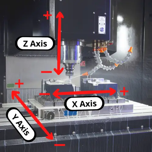
Let’s compare that to our 3 axis mill to see how they line up.

an illustration that shows the X, Y and Z axes on a CNC machine

How are coordinates used in CNC machining?

Most CNC machines use a conventional cartesian coordinate system and assign the order of axes movement as follows:

  • X-axis allows movement “left” and “right”
  • Y-axis allows movement “forward” and “backward”
  • Z-axis allows movement “up” and “down”

However, there are a few exceptions to this rule, that will depend on the machine model or manufacturing company.

Some machines can switch the Z and Y axis, which can lead to confusion. Be sure to check all these details in your machine’s manual.

Movement in the coordinate system is related to the movement of your cutting tool. Many times, the cutting tool may not move in one or more axes but instead the control will move the table to act as if the tool moved.

Machine reference point

Every CNC machine has its own origin point or Home location that will serve as the machine’s coordinate system’s origin.

The machine reference point is a known point for the CNC machine.

You might move the zero location using a work offset such as G54, but the machine is calculating everything based off the reference point.

The CNC control allows you to do this to make the program easier to create and understand.

Work coordinate system

A work coordinate system sets a new origin location for the machine to use when running the CNC program.

You wouldn’t want to program to random coordinate locations in your machine. You also wouldn’t want to make a new program every time you wanted to make the same part on a different CNC machine.

The solution is a work coordinate system.

We touched on it earlier but using a work offset such as G54, G55 or one of the others commonly available on CNC controllers allows you to set your part or a fixture as the origin location.

Once the part or fixture is set as the X, Y and Z zero location, the program can be run.

Using a work coordinate system or work offset allows the CNC programmer and operator more flexibility in their programs and setup.

Often the work offset origin location will be either be where a corner of the part or the center of the part intersects the top surface.

Absolute vs incremental coordinates

Everything we have talked about so far has been discussing absolute coordinates.

Absolute coordinates are a type of coordinates that are based on a fixed origin (zero) location.

In CNC machines, absolute coordinates are set using the G90 code.

There are exceptions but most CNC programs are mainly written using absolute coordinates.

The other type of coordinates that can be used are incremental coordinates.

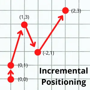
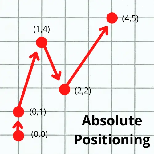
graph paper example of absolute positioning with multiple points as examples
graph paper example of incremental positioning with multiple points as examples

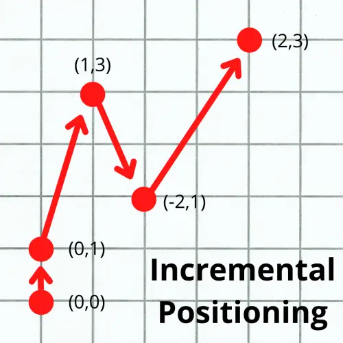
Incremental coordinates have a constantly changing origin location. Each time the CNC machine moves to a new location, that location becomes the origin. 

In other words, each new move is relative to the machine’s current location.

Incremental coordinates are set using the G91 code in a CNC program. They are usually reserved for specific, repetitive features such as a series of holes that need to be drilled or something similar.

The pictures above show the same machine movement in the two different positioning modes. The locations given to the machine are given in parentheses ( ).

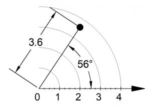
Polar coordinates

Credit “ToolNotes.com © 2021, used by permission”

Most beginners don’t need to be too concerned with polar coordinates, but it is still helpful to be aware that they exist.

Polar coordinates are another way of specifying machine locations, like Cartesian coordinates.

Instead of X, Y and Z locations, polar coordinates use a radius, an angle, and a Z location.

Polar coordinates vs cartesian coordinates

Polar coordinates make calculations easier with circular motion, arcs, and circular paths.

On the other hand, Cartesian coordinates make linear movement easier to comprehend, and it is far more commonly used.

CNC machines are set to operate with a cartesian system by default. However, most CNC machines and controls include the option to use polar coordinates if needed.

CNC machines with multiple axes

Hobbyist CNC machines usually work with three axes (X, Y, & Z) as explained above.

Industrial grade machines can often be found with one or more additional axes. The most common is the addition of a rotary 4th axis.

4th, 5th and 6th axis machines are not uncommon.  

Each of these axes rotates around one of the first 3 axes. The 4th axis rotates around X. The 5th around Y. The 6th around Z.

Ready to master CNC programming?

Try the free 30 minute intro course to see how simple and easy G code can be. Take the shortcut to becoming a G Code Master today!
Quick Guide to CNC Coolant Codes [M07, M08 & M09]

Which codes control coolant use on a CNC machine?

There are three main CNC M codes which control coolant use:

M07, M08 and M09.

M08 and M09 are the most common codes used. 

In addition, many machines have special coolant functions available such as through spindle coolant.

Special coolant codes tend to vary from machine to machine so make sure to check your individual machine for specialty coolant function.

Ready to master CNC programming?

Try the free 30 minute intro course to see how simple and easy G code can be. Take the shortcut to becoming a G Code Master today!
M07 [mist coolant]

The M07 code is a modal command which turns on mist coolant.

Mist coolant is compressed air and coolant (usually oil). 

It can be more efficient than flood coolant and in some situations be better at clearing chips than flood coolant, but it is used far less often than flood coolant with the M08 command.

M08 [flood coolant]

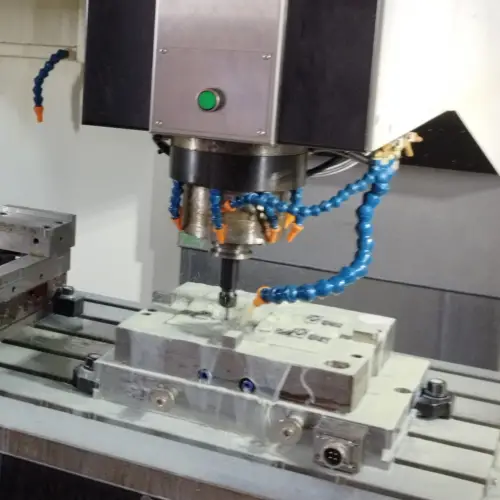
cnc machine table with coolant lines and spindle shown
Flood coolant on a workpiece

M08 turns on the coolant for the main spindle.

In general, you will find this coolant aimed directly at the cutting edge of the tool.

Flooding the area with coolant has multiple benefits. The coolant reduces the heat build up from the cutting action, lubricates the cutter and helps to clear chips from the cutting area.

These three benefits of using flood coolant all work to reduce any heat that is caused by the cutting action which helps extend the life of your cutting tool.

M09 [coolant off]

The M09 code is used to turn off both types of coolant flow.

You never want to turn off coolant while the cutter is still cutting. On the opposite end of things, you should never turn coolant on if the cutter is already cutting.

Always start and stop coolant flow when the cutter is not actively engaged with the part.

What is coolant used for in CNC machining?

Coolant for CNC machines is used to keep the workpiece and cutting tool at a lower temperature during the cutting process.

Both the cutter and the part tend to get hotter because of the friction created cutting.

Coolant is also used to clear chips from the cutting area. If chips are not cleared from the cutting area then you can end up recutting chips. Built up chips can also lead to built up heat which can damage your cutter or part.

Recutting chips also has a tendency to create poor surface finishes.

Types of coolant that can be used

The main types of coolant used on CNC machines are:

  • Air: This type of coolant reduces heat and clears the chips, but it does not lubricate the workpiece. This type of coolant is used more often with sensitive materials.
  • Mist: With mist coolant, the pressure of the coolant is kept low and less coolant is used. This can be beneficial if your CNC doesn’t have a coolant capture system. Mist coolant lubricates the cutter and clears chips.
  • Flood: This is also a low-pressure form of coolant. Flood coolant lubricates, removes chips and reduces heat buildup.
  • High pressure: High pressure coolant is similar to flood coolant. The only difference is that it hits the workpiece at greater than 1000psi. The higher pressure and higher quantity of coolant helps cool the cutter better and remove more chips.
  • Through spindle: Through spindle coolant delivers the coolant directly where it is needed. It is better at clearing chips in many cases because the coolant from the spindle pushes the chips out of a hole or pocket.

What is CNC coolant made of?

Coolants are categorized into four groups depending on the material that they are made of:

  • Synthetic fluids: They are made of lubricants and rust inhibitors usually dissolved in water. It is basically soluble oil mixed with water to create coolant.
  • Semi-synthetic fluids: These coolants are a mix between synthetic polymer and oil.
  • Soluble oils: They contain a mix of 40 percent or more of oil and the rest is water.
  • Straight oils: These ones are derived from petroleum, they are not diluted with water.

List of common CNC coolant brands

There are many different brands of CNC coolant available. Some of the most commonly used ones are:

  • Castrol
  • Chem Arrow
  • ChemTool
  • Fuchs
  • Hangsterfers
  • Master Fluid Solutions
  • Quaker Houghton
  • Qualichem
  • Tower Coolant
  • Yushiro

Frequently asked questions

Does every CNC machine have coolant capabilities?

Yes and no.

You can expect that industrial level CNC machines will have coolant capabilities.

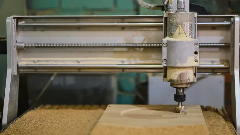
Home or hobbyist level machines such as CNC routers often do not have coolant capabilities, but they can usually be added on if needed.

cnc wood router
CNC router without coolant capability

Which code turns CNC coolant off?

The M-code to turn coolant off is M09.

However, there are other stopping commands that also turn off coolant such as:

Ready to master CNC programming?

Try the free 30 minute intro course to see how simple and easy G code can be. Take the shortcut to becoming a G Code Master today!
Quick Guide to CNC Compensation Modes [Cutter Comp, Tool Length Comp and Offsets]

Types of compensation


CNC machines have three main types of compensation:

  • Cutter compensation/tool diameter compensation
  • Tool length compensation
  • Work/fixture offsets

These compensation modes allow the machine to accommodate for things such as the location of a part in the machine or the size of a cutting tool.

Compensation allows the machine to adjust how it reads the CNC G code so that the same program can be used in multiple ways.

Using compensation modes allows the CNC to run the same program and get the same results even if the factors we mentioned above (cutting tool, workpiece location) are changed between runs.

The machine will have no problem adjusting for a new cutter as long as we tell the machine the diameter and length of the new cutting tool.

The values that tell the machine how long the tool is or what its diameter is are called offsets.

There are multiple compensation codes and offset codes.

Luckily, the list isn’t long. Let’s go through them one by one.

Ready to master CNC programming?

Try the free 30 minute intro course to see how simple and easy G code can be. Take the shortcut to becoming a G Code Master today!
Cutter compensation/tool diameter compensation


The first type of compensation is compensation that accounts for the size or diameter of the cutting tool. This is often referred to as simply cutter compensation.

There are two types of cutter compensation.

Before we talk about what cutter compensation does when it is on, let’s talk about how to turn it off.

G40 – Cutter compensation cancel


The two cutter compensation modes are both modal commands

This means that they stay on and in effect until they are changed or cancelled.

Selecting G41 or G42 switches between the two modes. If you want to turn off cutter compensation you will need to use the cancel command.

G40 is the off button for cutter compensation

Calling it in your program will cancel any active cutter compensation.  

Because modal commands stay on until changed or turned off, you often see cancel commands used in safety blocks of code found at the beginning of the program or a new section of the code such as when changing tools.

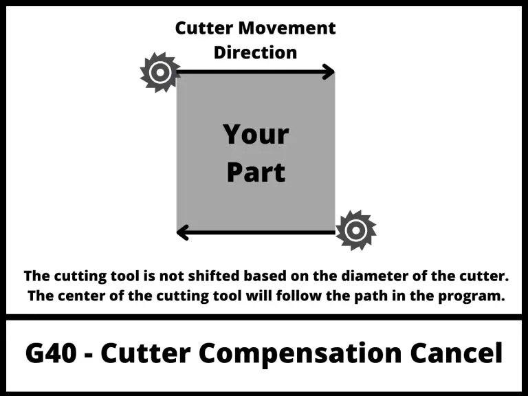
The illustration below shows how the CNC will move when cutter compensation is off.

illustration that shows how a CNC will act when there is no cutter compensation mode active

G41 – Cutter compensation left


G41 is the most common cutter compensation. It is used when climb milling.

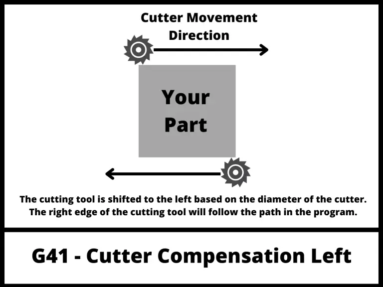
The G41 code tells the CNC to shift the cutter to the left of the cutting path to account for the size of the cutter.

See the pic below for help understanding what that means in practice.

illustration that shows how a CNC will act when using cutter compensation left with the G41 code

G42 – Cutter compensation right


G42 is used when conventional milling.

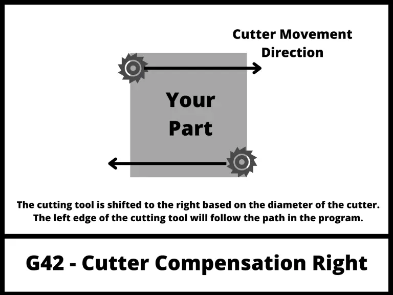
The G42 code tells the CNC to shift the cutter to the right of the cutting path to account for the size of the cutter.

G42 is not used nearly as often as the G41 code. 

illustration that shows how a CNC will act when using cutter compensation right with the G42 code

D offsets


illustration of a cnc cutting tool that shows what an D offset is

Diameter (D) offsets are the location where the size (diameter) of the tool is stored in the CNC control.

D01 will be the offset where the size information is stored for tool #01. D02 will be for tool #02 and so on.

D offsets are set with the D code.

Tool length compensation


G43 – Tool length compensation +


G43 is the command to turn on tool length compensation. 

Just like G40-G42, G43 is modal which means it will stay on until changed or canceled.

G43 is for positive tool length compensation. You should be aware there is also a negative tool length compensation mode (G44) but it is rarely used and not something that beginners should be worried about.

G43 is used frequently and you can expect to see it used in 99.9% of the CNC programs you will come across.

G49 – Tool length compensation cancel


Just like G40 cancels cutter compensation based on the diameter of the tool, G49 does the same for tool length compensation.

Like many other cancel commands, G49 can be found at the beginning or ending of different sections of code to ensure the machine is in the correct mode as tools are changed and different operations are performed.

H offsets


illustration of a cnc cutting tool that shows what an H offset is

Height (H) offsets are the location where the length of the tool is stored in the CNC control.

This value is the difference in location between the end of the spindle and the end of the cutting tool.

H01 will be the offset where the length of tool #01 is stored. H05 will be for tool #05 and so on.

Height offsets are set with the H code.

Fixture/work offsets


Work offsets are used to tell the machine where it should reference all program values from.

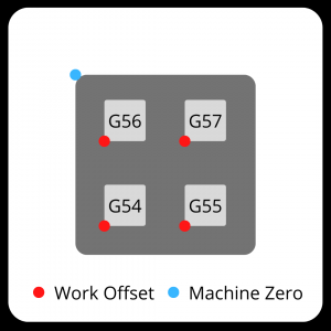
For example, imagine if you wanted to machine four separate parts to be all the same. You could load all four parts into your CNC machine and set a work offset location for each separate part.

Once the work offsets are stored, you could call out the first work offset and then run your program.

Next you could call out the next work offset and run the same program again. This would run the same program in a new location resulting in two of the same part. And rinse and repeat as much as needed.

visual to show cnc work offsets G54-G59 with the zero locations shown
Example of a CNC machine set with 4 work offsets

G54-G59 – Work offsets


G54 through G59 are the standard work offsets that you can expect to find on just about any CNC machine.

Work offsets identify an X, Y & Z coordinate zero location. Work offsets go by many other names such as program zero, part zero, zero location, etc.

Some machines may be capable of storing many more work offset locations, but it is best to concentrate on the most common codes first. Check your individual machine documentation to learn how to program with more work offsets.

If you are very new to CNC programming with G code then be on the lookout for a G54 code. 

This is the first work offset and as a result is the most common one used. Often shops will only have a need for this single work offset. As shops and machine become more advanced you can expect to see more usage of additional work offsets.

Just like the other offset modes we have talked about; work offsets are also modal commands.

Expect to find them in the safety blocks of code and because they are important enough to be included in the safety block section, you should be very careful about making sure you have identified the correct work offset at all times in the program.

Ready to master CNC programming?

Try the free 30 minute intro course to see how simple and easy G code can be. Take the shortcut to becoming a G Code Master today!
Beginners Guide to Rapid Traverse for CNCs

Key Points

  • Rapid traverse is full speed movement
  • Rapid travel and rapid traverse are the same thing
  • The G code for rapid traverse is G00 on CNC mills and lathes
  • The rapid speed can be adjusted using the rapid override

What is rapid traverse?

Rapid traverse, sometimes referred to as rapid transverse or rapid travel, is used for moving a machine tool around the workpiece as fast as possible. 

Depending on the type of machine tool, this is accomplished in different ways. See below for more information related to CNC and manual machines.

How fast does the machine move in rapid traverse?

First let’s talk about speed.

Rapid traverse speeds vary based on the machine.  A good quality desktop CNC will usually be capable of speeds around 100 inches per minute (IPM).

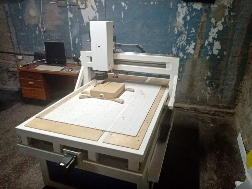
homemade cnc router machine
Homemade “garage” CNC

Larger, industrial grade CNC can often move at speeds of 1,000 inches per minute or more. 

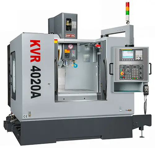
industrial cnc machine
Industrial grade CNC mill

No matter what type of CNC you are using, you will want to make sure that nothing is in the way when these moves are being made in a CNC machine. 

Crashing a CNC at normal speeds is bad enough, crashing a CNC at rapid speeds could be catastrophic.

Can rapid traverse speed be adjusted?

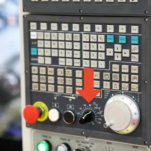
cnc control board with rapid travel dial identified with arrow
Rapid Override Dial

Most CNC machine controls have an adjustment to dial back the rapid travel speed. This is often referred to as Rapid Override or something similar. This override allows the CNC operator to adjust the rapid speed, usually in the form of a percentage of the full speed.

Some shops need to run full speed. Time is money after all, but many machine shops will dial things back a little for safety.

How does the CNC move during rapid travel?

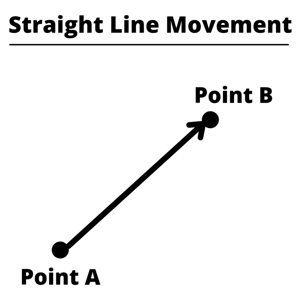
straight line movement example

Newer CNCs will move in a true straight line fashion, however some older CNCs can process the command in different ways.

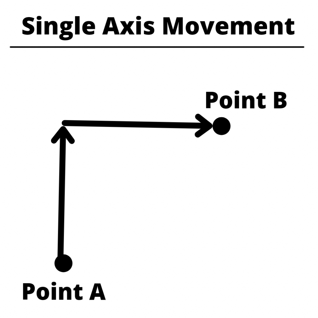
Some machines may only move one axis at a time while others will move in other strange ways. The most important thing is to be aware how your specific CNC control will process the rapid travel command and create your program to account for this movement.

Because various machines will process commands in different ways, this means you may not be able to take a program and a setup and run it on a different machine.

What is the G code for rapid traverse?

rapid traverse code example

The G code for rapid movement is G00. 

This applies to both CNC mills and lathes. 

In the example above, G00 is the code for rapid traverse and the X and Y values are the position that the machine is to rapidly move to.

Rapid movement can happen in the Z axis as well.

What should you think about when using rapid travel?

When you are zipping your CNC back and forth think about:

  • Part location – it can be easy to forget about a step in your part and attempt to move over the top of you part at a Z height that is too low
  • Fixturing – similar to your part location, remember that you often have clamps, vises, etc. that will be in your machine and it’s best to avoid them
  • Removing material – don’t cut in rapid mode, it will result in size issues and poor surface finishes at best

Rapid traverse in manual machining

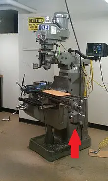
bridgeport milling machine with rapid power feed pointed out
Power feed marked by red arrow

Many manual machines, such as a Bridgeport mill, use a power feed to rapidly move around the workpiece. 

These power feeds are not as fast as a CNCs rapid moves but they are still much quicker than the standard speed which usually involves cranking a handle to position the machine. 

Related articles

For more information see these related articles:

Guide to CNC M Codes [List and Quick Reference]

What are M codes used for?

In CNC machining, M codes are used to control machine and miscellaneous functions.

This includes turning off and on features such as the machine spindle as well as coolant functions. They also control how the CNC reads and flows through the program.

M codes are the second most common codes used in CNC programming. 

We’ve laid out what each M code does, but remember that some CNC makers switch things around a little bit.

You can bet that the most common codes such as the ones for starting and stopping your spindle, coolant and program will be the same but some of the others might vary.

For anyone new, be sure to check out our post on the first M codes to learn to make sure you start with the important stuff.

List of M Codes

When the machine gets to this code it will stop everything, including the spindle and coolant until the operator tells the machine to continue on.

Learn more about the M00 code

The machine will check the control panel and if the optional stop switch is on, the machine will stop just like with M00.

Programs often have optional stops placed at the break of sections in the program such as the start of a hole drilling sequence.

Learn more about the M01 code

A leftover from the NC days. Ends the program without rewinding to the start again. 

In many machines now, M02 is no different than M30. How it gets treated depends on the specific CNC control model.

Learn more about the M02 code

Turns the spindle on in the clockwise direction. This is the spindle direction used by most cutting tools.

Learn more about the M03 code

Turns the spindle on in the counterclockwise direction. 

Learn more about the M04 code

Turns on a coolant mist. Some machines treat it as coolant source 1 on.

Learn more about the M07 code

Turns the coolant on to soak the workpiece. Some machines treat it as coolant source 2 on.

Learn more about the M08 code

Turns off all coolant sources.

Learn more about the M09 code

M19 CNC M Code

M19 - Orient Spindle

Gets the tool ready for tool change. Aligns the keyways. 

The M06 code will do this as well but calling it ahead of time can make the tool change process faster.

Stops everything including the spindle, movement, coolant and will go back to the beginning of the program.

Learn more about the M30 code

Frequently Asked Questions

What are M codes used for in a CNC program?

M codes are used for turning miscellaneous functions on and off such as the spindle and coolant.

What is the difference between G and M codes?

M codes turn things on and off while G codes switch modes in the machine such as working in inches or mm.

G codes also prepare the machine for functions such as canned cycles for drilling or boring holes.

What other types of CNC codes are used in CNC programming?

There are many other CNC codes that get used such as:

  • Location based codes such as A, B, C, I, J, K, X, Y & Z
  • Machine related codes such as F, R & S
  • Offset related codes such as D, H & T
  • Program related codes such as G, N, O, P & Q 

Absolute and Incremental CNC Positioning Modes [G90 & G91]

a graphic of a cnc machine with text that says learn g code today cnc positioning modes

What is a CNC positioning mode?

In CNC programming, a positioning mode refers to the way the CNC machine will read and understand every new XYZ location it is given.

For CNC machines, there are two positioning modes available.

The two modes are absolute positioning and incremental positioning.

Absolute mode is set using the G90 code and incremental mode is set using the G91 code.

Want to learn more about CNC G Code?

G90 [Absolute Positioning]

Absolute positioning is the mode that most of your CNC programs will be written in.

The alternative is incremental mode, and it is usually reserved for specific sections of a CNC program such as repetitive features.

The G90 code sets the machine into absolute positioning mode.

When G90 is active all locations will be given relative to a fixed point called the origin.

When we discuss coordinates, we list them in the order XYZ. If you see (1,2,3), then X=1, Y=2, and Z=3. Sometimes this is simplified to only show the X and Y coordinates such as (4,5). In this example, X=4 and Y=5.

an illustration that shows the X, Y and Z axes on a CNC machine
3 axis CNC mill

Now that you understand coordinate locations, let’s talk about the origin again.

The origin is the (0,0,0) location. This means X, Y & Z all equal zero at this one point.

In absolute positioning mode the origin (sometimes called the zero location) is a fixed point. 

This means it doesn’t move.

Using absolute positioning, you will set a location in your CNC machine as the origin and all locations in your CNC program will be given from that origin.

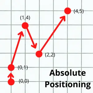
Each new machine location is given in parentheses () below. Notice how all locations are relative to the initial (0,0) location.

graph paper example of absolute positioning with multiple points as examples

Advantages and disadvantages of absolute positioning

Advantages

  • Easier to track the location of your cutting tool throughout the program
  • Changing one location doesn’t affect all of the following locations in the program

Disadvantages

  • Code can be hard to read for repetitive tasks such as drilling a large number of holes

G91 [Incremental Positioning]

While absolute positioning with G90 has a fixed origin or zero location, incremental positioning with G91 has a zero location that changes with each move.

Every time the cutting tool moves to a new location, that location becomes the new zero point.

Compare the picture below to the absolute positioning pic:

graph paper example of incremental positioning with multiple points as examples

The numbers in parentheses () are the coordinates that the machine would be given to move to each new location in the two different positioning modes.

If at any time in the program we gave the machine a (0,0) coordinate in absolute positioning, the machine would return to the origin in the lower left corner.

If we did the same in incremental mode, the machine wouldn’t move. 

In incremental mode the origin changes each move and a (0,0) would tell the machine to move zero units in both directions.

Giving the CNC a (0,0) location in incremental mode would tell it to stay put.

Advantages and disadvantages of incremental positioning

Advantages

  • Easier to read code for repetitive features and patterns
  • Can reuse incremental sections of code easily either in the same program or as a subprogram

Disadvantages

  • Each location affects every location after it so changing one requires changing all others after it

Where you will find G90 and G91 in a CNC program

Setting the correct positioning mode is an important part of any CNC program.

For this reason, the positioning mode is often set in the safety lines of the program.

Safety lines are a line or lines of code that show up at the beginning of the program and at specific locations in the program. They are used to make sure the machine is prepared to run the next section of code.

They get used at the beginning of the program to set all the necessary modes before starting machining.

Safety lines often show up again when a tool is changed or a new machining operation is being performed.

Check out the “sections” of a small CNC program below:

  • Program start
  • Machine exterior profile of piece
  • Drill pattern of holes
  • Add counterbores to holes
  • Program end

At the start of each of these sections you can expect to find safety lines that set the necessary modes needed for the upcoming operation. Doing this allows individual sections of the program to be re-run if needed.

Imagine you ended the program in incremental mode after using the counterboring canned cycle. Then you measure your part and realize the length and width are oversize.

Bummer!

So you decide to adjust your offsets and re-run the exterior profile section of the program.

If you don’t have safety lines that make sure the machine is set to absolute positioning mode, then the machine will remain in incremental mode and interpret the code very differently.

Setting your positioning mode is very important. Even if it doesn’t change often in the program, the codes get used frequently to make sure all the correct modes are set.

Which positioning mode is better?

Neither positioning mode is better, but they do have their own uses.

The body of most CNC programs will be written in absolute positioning mode. 

This is because it is easier to understand and visualize where the cutter is.

In absolute mode you only need to know where the origin and the new location are to understand your position in the machine.

In incremental mode you need to know every move the machine has made to know what position you are at. That can mean a lot of calculations to figure out where you are located.

This might make it seem like absolute positioning mode is the best and should be used for everything, but that is not always the case.

Incremental mode is great for patterns and features that repeat. 

This means incremental mode is often used when working with canned cycles.

Which codes will be affected by your choice of positioning mode?

Any code that uses XYZ movement as part of the code will be affected by your positioning mode.

All movement codes are affected by your choice of positioning mode:

Canned cycles are another set of commonly used codes that will be affected. They vary from machine to machine but generally canned cycles are the G73-G89 codes.

Another important code that is affected by your positioning mode is G28. The G28 zero return command can behave very differently from one mode to the other, so make sure you know how your machine will react before using it.

This isn’t a complete list of codes. 

There are many more that are affected by your choice of positioning mode, but this is a good start for anyone new to CNC machining.

As always, know your machine and check the manual if available to fully understand how it will react to any code you give it.

Frequently asked questions about CNC positioning modes

What happens if you don’t select a positioning mode?

On most CNC machines, there is a default positioning mode.

If you don’t use the G90 or G91 command, the machine will stay in the default mode.

The default mode is most often set to incremental mode for safety reasons.

It is not recommended to rely on the default modes of your machine to make sure you are in the correct positioning mode. 

You should always set the positioning mode you need with either a G90 or G91 code.

Can you use the G90 and G91 codes on the same line/block?

No, it is not possible to use the G90 and G91 commands on the same line.

Both G90 and G91 are modal commands from the same group. This means turning one on turns the other off.

With G90 and G91, only one code can be active at a time.

What could happen if you use the wrong positioning mode?

To put it simply, your machine could crash.

Moving to the (0,0) location in absolute mode with G90 will bring you to the part zero location. This could be any location you chose on your workpiece.

Moving to the (0,0) location in incremental mode with G91 will not move your machine at all.

These are two very different commands being executed based on the positioning mode.

Forgetting to set the correct positioning mode can cause the CNC machine to act in very unexpected ways for the programmer. Unexpected is never good when it comes to CNC machining.

Because being in the correct positioning mode is so important, the positioning mode is often set in the safety lines of the program.

Safety lines are used to make sure the machine is in all of the correct modes before running a section of the CNC program.

Want to learn more about CNC G Code?

Modal G & M Codes for Your CNC [What They Do & How to Use Them]

a graphic of a cnc machine with text that says learn g code today modal codes

What is a modal command?

Modal commands are a type of CNC code that stay active once turned on until the code is either turned off or switched to another code in the same group.

For example, if left cutter compensation is turned on with G41 it will stay on until either the G42 code switches the machine to right cutter compensation or the G40 command is used to turn off cutter compensation altogether.

Want to learn more about CNC G Code?

Why and how are modal commands used?

Modal commands are useful because they increase productivity. 

Modal commands can save time for the CNC programmer and make the CNC program smaller.

Using modal codes allows you to not have to write the same code repeatedly. This also has the added benefit of making the program easier to read.

By using modal commands you set the machine modes once and then switch them as needed.

A good example of this is your unit mode.

Most programs will be written in either inches or millimeters. It is not common for a program to switch between the two unit types. 

Using modal commands allows you to use the G20 code and set the machine in inch mode at the start of the program and leave it on.

Without the capability to use modal commands, you would need to tell the machine that every new line of code was in inches. 

This would make for a very busy, hard to read program with a bunch of codes repeated throughout.

Modal commands make the programming easier to create and easier to read.

Remember you can only have one modal command from the same group active at a time. 

Also, there are some commands which are one-shot codes. This means they only affect the line they are used on.

The various modal groups are shown below.

Modal command groups

To really drive the point home, remember:

You can only have one modal code active from each group. 

If you use G20 to put the machine in inch mode and then use the G21 command to put the machine in metric mode, they are not both active. The G20 command gets turned off when the G21 command is turned on.

Some of the groups of codes have a cancel command which can be used to turn all codes in the same group off. 

Not every code group has a cancel command though. 

For instance, you will always be in either G20 (inches) or G21 (mm). It is not possible to turn both off. One or the other must be active.

If a code group has a cancel command, it is discussed in the individual group sections below.

Movement [G00, G01, G02, G03]

One of the most frequently used group of codes is movement codes.

CNC machines need to move to cut, drill, and grind parts along with many other functions.

Many times, large portions of your CNC program will be exclusively movement codes as the machine performs its cutting operations.

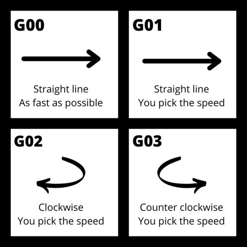
In the movement group of codes there are four different codes:

You move with G01, G02 and G03 to make cutting movements to make all kinds of shapes and cuts on the part, but what about G00?

G00 is rapid movement and is used to move the machine as quickly as possible when it is not in the process of cutting.

Moving rapidly reduces the total machining time, otherwise known as cycle time. While this might not make a huge difference for making one part in your garage, shaving a minute off each part for an order of 1,000 pieces really adds up.

a comparison of the type of movement created with G00, G01, G02 and G03 cnc g codes

Units [G20, G21]

comparison of units of measurement for cnc programming

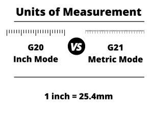
We talked about it above but the codes used to set your units are very important.

G20 sets the machine in imperial units (inches) and G21 sets the machine in metric units (mm).

Switching between units is not advised. Set your units and stick with them.

Cutter compensation [G40, G41, G42]

Cutter compensation is a mode that allows the machine to adjust for the size of the cutting tool.

This allows the same program to be used with multiple different cutting tools. Without cutter compensation, you would need to write a new program each time you had a new cutter.

illustration that shows how a CNC will act when there is no cutter compensation mode active

The first code in the group is the cutter compensation cancel command, G40. When this code is active, the CNC will move the center of the cutting tool along the tool path listed in the program.

This is useful when you want to drill a hole at a specific location.

The two cutter compensation modes which cause the machine to adjust the tool path are:

illustration that shows how a CNC will act when using cutter compensation left with the G41 code
illustration that shows how a CNC will act when using cutter compensation right with the G42 code

Both modes adjust the path of the cutting tool so that the edge of the cutter follows the toolpath of the program.

G41 is used when climb milling and G42 is used when conventional milling.

G41 is used far more often than G42.

Both G41 and G42 take into account the D offset value to tell the CNC how much to adjust the tool path. 

The D offset value is listed when turning on cutter compensation. For example, to turn on left cutter compensation with the first D offset the line of code would be:

G41 D1

Tool length compensation [G43, G49]

an illustration of a cnc machine that shows how a g43 code offsets the program

Just like the diameter of the cutter needs to be accounted for, so does the length of the cutting tool.

G43 is the code to turn on tool length compensation. 

This code is used along with an H offset value which is stored in the CNC controller similar to the D offsets used in cutter compensation.

Tool length compensation is used for many of the same reasons cutter compensation with G41 and G42 is used. 

It allows the machine to adjust for the length of the cutting tool and not require a new program to be created each time the tool is changed.

Technically, G43 is for positive tool length compensation and G44 is for negative tool length compensation.

For anyone just learning about modal commands, they should ignore G44 for the time being. 

G44 is not used often and is not something that a beginner can expect to deal with.

Focus on G43 and G49 when first learning CNC programming.

Speaking of G49. G49 is the code to cancel tool length compensation. 

Remember cancel just means turn it off.

You might think that you would need to turn off tool length compensation much like you would with cutter compensation, but this is rarely true.

Instead, the machine will switch between tools by using different H offsets for different length cutters.

When tool length compensation is off using a G49 code, the machine will move the tip of the spindle to each new location instead of the tip of the cutter. 

Because you will almost always have a cutting tool in your spindle, tool length compensation with G43 is almost always on.

Fixture/work offset [G54-G59]

Fixture offsets, sometimes called work offsets are how the machine knows where your part is located in the machine.

They tell the machine the zero location in the three axes (X, Y, & Z). The machine will execute the program based on this zero location.

Using work offsets allows you to easily set up for a different part or even use one program to run multiple parts at once. 

You can tell the machine the location of your first part by using G54, run your program then set the work offset to G55 so the machine knows where the second part is and proceed to run the same program again.

visual to show cnc work offsets G54-G59 with the zero locations shown

Just like your D and H offsets allow flexibility in your CNC programming and setup, work/fixture offsets with G54-G59 do the same.

It should be noted that G54 through G59 are the most common work offsets used and can be found on most machines. 

In addition to these six offsets, most machines (especially new models) will be able to use many more offsets. How they are used varies from machine to machine so check your machine manual.

Positioning mode [G90, G91]

Positioning modes tell the CNC machine how to interpret each new location it is given.

There are two types of positioning modes which can be used:

Absolute positioning with G90 tells the machine that all dimensions are measured from the datum/origin (0,0,0). This is a fixed point in the machine that will not change unless the work offset is changed.

Incremental positioning with G91 tells the machine that each new location becomes the zero location (0,0,0).

The pictures below show the same tool path in both positioning modes. The coordinate location of each new move is listed in parentheses ().

graph paper example of absolute positioning with multiple points as examples
graph paper example of incremental positioning with multiple points as examples

Canned cycles [G80, G81, G82, G83, G84, G85, G86, G87, G88, G89]

Canned cycle are modal commands which are used for programming repetitive CNC operations.

They have the benefit of making your CNC program both shorter and easier to read and understand.

Canned cycles are a big topic on their own so I will only include a brief description of what each code is used for. If you need more information about any of the individual canned cycles, then click the links below:

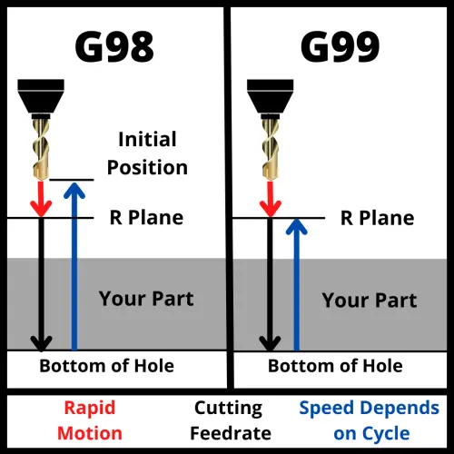
Plane returns [G98, G99]

Plane returns tell the machine how to act after finishing a canned cycle. 

The two options are:

G98 returns to the point where the canned cycle was started. 

G99 returns to the R plane, which is the point where the controlled feedrate (not rapid) started.

visualization of how a cnc machine moves using g98 and g99 codes shows motion of travel for the machine

The R plane is lower than the initial point. This can allow for shorter machining time because the machine is not travelling as far.

Often a series of holes will be drilled and both G98 and G99 return codes will be used in the process.

The G99 code gets used when the machine is able to stick close to the part and move to the next hole.

The G98 code is used when the machine needs to retract further, for instance if you needed to avoid a clamp or something else in the way of your cutter.

G98 retracts further and takes longer but is generally the safer option.

You should be careful using both G98 and G99 though.

Pay close attention to the initial point (your Z height when starting the canned cycle) and your R plane (set with the R code in your canned cycle callout).

The initial point should be set at a level that is higher than any objects in the machine such as the part itself, clamps, fixtures, etc.

Plane selection [G17, G18, G19]

There are 3 codes that tell the machine which plane to work in:

  • G17 for the XY plane
  • G18 for the XZ plane
  • G19 for the YZ plane

Most programs will be written using the G17 code and work in the XY plane.

Modal M codes

In addition to the modal G codes listed above, there are also modal M codes available for controlling various machine functions.

These modal M codes work in the same way as the G codes. Once they are used, they will stay on until canceled or switched to another code in the same group.

Spindle commands [M03, M04, M05]

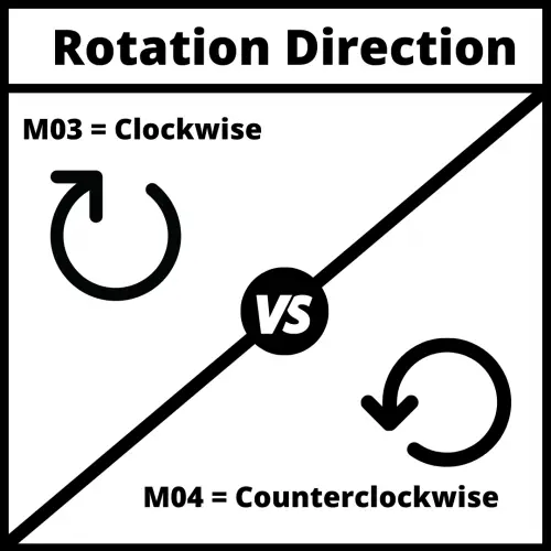
Spindle direction

This group of modal commands controls the CNC spindle. They are:

Coolant [M07, M08, M09]

The next group of modal M codes controls the machines use of coolant.

Mist coolant is usually a combination of coolant and compressed air but this can vary from machine to machine and sometimes you may find that it is only compressed air or not even available on your specific machine.

Flood coolant is the normal CNC coolant mode where the machine floods the cutting tool and workpiece with coolant.

M07 modal command turns on the mist coolant and it will be directed to the material cutting.

Other modal commands

There are many other modal commands which can be used for CNC programming. 

They vary by machine and not all machines will have each type of modal code.

The codes laid out here are the most common modal commands and will give anyone trying to learn CNC programming a good start towards learning the ins and outs of modal commands.

Frequently asked questions about modal codes

Modal vs one shot codes

While there are a lot of modal codes, not every CNC code is modal.

There are also one-shot (non-modal) commands as well. These codes only affect the line they are used on.

A couple of the commonly used one-shot codes are:

What happens if I don’t set a modal code?

When the CNC machine starts up it sets the machine to various default modes as set in the setup parameters of the machine.

It is never advised to rely on the startup modes of the machine to create your program. It is always better to call out any needed codes specifically in your program.

If you don’t set a modal command, the machine will remain in the default modes as set in the system parameters.

Want to learn more about CNC G Code?

Ultimate Guide to CNC Codes

Here is our Ultimate Guide to CNC Codes. Below is a list of CNC codes with a description of what they are.

Click on the code if you want to find out more including multiple examples to help you understand how to use them in your programs.

A - Rotation Around the X Axis

Rotates around the 4th axis of the machine if equipped.

B - Rotation Around the Y Axis

Rotates around the 5th axis of the machine if equipped.

C - Rotation Around the Z Axis

Rotates around the 6th axis of the machine if equipped.

Specifies the tool diameter offset to be used for cutter compensation (G41 and G42).

Learn more about the D code

Sets the feed rate to be used for movement. The feed rate is used when moving using codes such as G01, G02 & G03.

The feed rate is not used when using rapid travel (G00).

Learn more about the F code

Sets various modes in the machine or prepares the machine to perform a function such as a canned cycle.

Learn more about G codes

Specifies the height offset to be used when turning tool length compensation on (G43) or off (G49)

Learn more about the H code

I CNC Code

I - Radius Center in X Axis

Identifies the location of the center of a radius for a circular move relative to the current X axis location. 

J CNC Code

J - Radius Center in Y Axis

Identifies the location of the center of a radius for a circular move relative to the current Y axis location. 

K CNC Code

K - Radius Center in Z Axis

Identifies the location of the center of a radius for a circular move relative to the current Z axis location. 

L CNC Code

L - Number of Subprogram Repetitions

Used with the M98 subprogram call command. L lists how many times the subprogram will be repeated.

M codes turn on and off various machine functions such as the spindle or coolant. 

They are also used for program start and stop functions.

Learn more about M codes

Identifies the sequence or line number of the program. They are not required but they can help make a CNC program easier to follow. 

Learn more about the N code

The program number is the first CNC word in the program.

Learn more about the O code

When used with an M98 code, P identifies the subprogram number.

When used with G04 or canned cycles, P specifies the amount of time to dwell.

Learn more about the P code

Used with G73 and G83 peck drilling cycles. Q identifies the depth of each drilling peck before the drill backs up to break chips.

Learn more about the Q code

When used with G02 and G03, R specifies the size of the circular curve to be machined.

When used with a canned cycle such as G73, R specifies the location of the rapid plane.

Learn more about the R code

Sets the speed of the spindle.

Units are in revolutions per minute (RPM)

Learn more about the S code

Selects a tool to prepare it for tool change. M06 will cause the CNC to swap the currently loaded tool with the one selected with the T code.

Some machines do not require the use of a M06 code and will swap tools by simply using the T code.

Learn more about the T code

Specifies the location to be moved to in the X axis. 

The distance will be affected by whether the machine is in absolute (G90) or incremental (G91) mode.

Learn more about the X code

Specifies the location to be moved to in the Y axis. 

The distance will be affected by whether the machine is in absolute (G90) or incremental (G91) mode.

Learn more about the Y code

Specifies the location to be moved to in the Z axis. 

The distance will be affected by whether the machine is in absolute (G90) or incremental (G91) mode.

Learn more about the Z code

; - End of Block

Signifies the end of a block of code. A single block will usually consist of one line of code.

Useful when testing code by stepping through the blocks in single block mode.

Slash Block Skip CNC Code

/ - Block Skip

Used together with a switch on the CNC control. 

When the switch is on the machine will read and execute lines that start with the / character. When the switch is off, these lines will be ignored.