Quick Guide to CNC Subprograms [Tips & Tricks]

What is a subprogram in CNC programming?

Subprograms are a separate CNC program chosen to be run from within another program. 

Subprograms can be run (called up) from the main CNC program or from within another subprogram.

They are used to perform repetitive machining operations or sequences such as drilling, counterboring and countersinking a hole.

CNC machines run the lines of code in a program in order. 

Using subprograms allows the programmer to jump around to different sections of the current program or to run a different program and come back to the current program.

Ready to master CNC programming?

Try the free 30 minute intro course to see how simple and easy G code can be. Take the shortcut to becoming a G Code Master today!

What is the difference between a subprogram and the main program?

The commands to end the main program and a subprogram are different.

The main CNC program ends with either M30 (most machines) or M02 (older machines) code. 

No further code will be run after either of these codes.

A subprogram ends with the M99 command

The M99 code returns the machine to the program which called the subprogram. The machine will continue to run code in this program.

CNC codes used when working with subprograms

How to call a subprogram

There are two ways to run subprograms: M97 and M98.

The difference between M97 and M98 is the program location they move to.

M97 will jump to a new line in the current program.

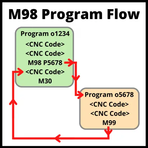
M98 will run an entirely different program.

Format for using M97

The format for using an M97 code is:

M97 P1234 L5

This line of code will tell the machine to move to line N1234 of the current program. The L code tells the CNC machine to run the subprogram five times. 

The L code can be left out if the subprogram will only be run once.

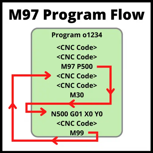
Line 1234 will be after the program end command (M30). Once the machine reaches the M99 command it will return to the line after the example shown above.

Format for using M98

The format for using an M98 code is:

M98 P5678 L2

This line of code will tell the machine to go run program number 5678 two times. The L code tells the CNC machine to run the subprogram twice. 

The L code can be left out if the subprogram will only be run once.

Program 5678 will perform any necessary machining functions and then end with an M99 command instead of M30. The M99 command will make the machine return to the line after the example shown above.

On the other hand, both commands (M98 and M97) use parameters K (or L) as the number of repetitions of a given subprogram. The use of the letter K or L depends on the CNC model. Always check the machine’s manual for further details.

Subprogram example

Main program

O1234
G21                             (metric mode)
G17 G40 G80           (select XY plane, cancel cutter compensation and canned cycles)
G91 G28 Z0              (home z axis)
M03 S1200               (turn spindle on)
G90 G54 G43 H1     (incremental mode, select work offset, turn on tool length compensation)
G00 X5.0 Y5.0          (rapid to hole #1 location)
Z2.0                            (position tool above part)
M98 P5555               (run subprogram)
G28 Z0                       (home z axis)
M30                            (end program)

Subprogram

O5555
G91                             (set incremental movement mode)
G81 Z-10.0 F200     (drill hole #1)
X5.0                            (drill hole #2)
Y6.0                            (drill hole #3)
X-5.0                           (drill hole #4)
G00 Z20.0                 (rapid to safe location above part)
M99                            (return to main program)

In the example above, the machine will create a pattern of four holes. This pattern could be easily repeated by moving to the start of the pattern in a new location and running the subprogram again.

To do this the location of the repeated pattern would be listed after the subprogram call in the main program and the subprogram call of M98 P5555 would be listed again. The machine would then make the same pattern of holes in the new location.

What are subprograms used for?

Subprograms are used for repeating tasks. 

This can be machining of a part or controlling the machine itself.

Part related subprograms

Most of these subprograms include canned cycles in their lines of code to perform repetitive machining operations such as drilling, pecking, tapping, threading, bearing, and boring.  

They also help to run the same program in different parts of the workpiece, even if they don’t include canned cycles.

This can include rotating or changing the tool, contouring or finishing.

Machine related subprograms

Subprograms can also be used to control the machine.

Changing a tool in the CNC might consist of turning the coolant off, turning the spindle off and moving it to a safe location, setting or canceling a variety of modes, and finally switching the tool.

A subprogram can be created to automate the tasks and make sure it is executed the same way each time. 

This makes the operation less prone to errors or crashes.

This benefit only gets better as the amount of operations performed gets longer.

Benefits of using a subprogram

The greatest benefit of using subprograms is reducing the lines of code which makes the program easier to read and edit.

Subprograms can also reduce the number of errors in the program. Less lines of code means less possible sources of problems.

Drawbacks of using a subprogram

Subprograms are meant to make the program easier to work with for both the programmer and anyone using it. If not done correctly, they can have the opposite effect.

Programmers should remember that part of their job is making sure that the program is easy to use for the operator.

It can also be easy to have the wrong modal commands or offsets chosen when starting or ending a subprogram. Following a good program format that uses safety lines or blocks of code can protect from this happening.

If it is important that a mode or offset is needed in a specific section of your program, it is best to use the necessary code to make sure things are set correctly. Assuming your machine is in the correct mode already is dangerous.

Making subprograms inside your subprograms (nesting) also has the potential to cause confusion. Repeatedly switching between programs can be confusing for both programmers and operators.

For a more in-depth description of subprogram nesting, see additional info on the topic further down in this post.

Differences between subprograms and canned cycles

Subprograms are small blocks of code used to perform repeatable machining operations or functions.

Canned cycles are commands that give the machine instructions for a pattern of movements used to simplify code.

Canned cycles are used for operations that the majority of CNC users will need such as drilling or counterboring a hole. Subprograms can be made custom to the needs of the individual machine user.

In a way, canned cycles are like mini subprograms that can be used easily in your program without needing to create a separate subprogram.

There are often times where canned cycles are used together with subprograms to increase the efficiency of the program even further.

How do modal commands work in subprograms?

Modal commands work the same way as they do in the main program. This means they stay on until changed or turned off.

If a modal command is on when starting the subprogram, it will stay on while running the subprogram. The same is true when switching from the subprogram to the main program.

The safest thing to do is make sure your safety blocks cover the required codes for each section of code.

What is nesting in CNC programming?

So far we have concentrated on running a subprogram from our main program, but did you know you can also run a subprogram from within a subprogram?

This is called nesting.

Nesting can be a powerful tool but can quickly get out of control. 

Most CNC controllers will allow up to four level deep nesting.

This means calling a subprogram in a subprogram in a subprogram in a subprogram in your main program.

Confusing right? That is why in most cases it isn’t a good idea to nest that deep. For most applications, one level deep is enough.

Even two level nesting can be hard to follow. Three and four levels are definitely not advised if you are reading this post.

The bulleted list below shows how subprogram structure works.
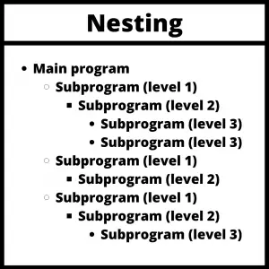
bullet point list used to show nesting structure of CNC programs

Tips for numbering your subprograms

Create a system for numbering your programs and subprograms to avoid confusion.

Some choose to set aside blocks of numbers for each type of program. For example, O0001-O4999 for main programs and O5000-O9999 for subprograms.

Others make their subprograms closely follow their main program numbers. If the main program is O1000 then the subprograms will be O1001, O1002 and so on.

Ready to master CNC programming?

Try the free 30 minute intro course to see how simple and easy G code can be. Take the shortcut to becoming a G Code Master today!
G42 CNC Code Explained: An Easy Intro for Beginners [Cutter Comp Right]

What does a G42 code do?

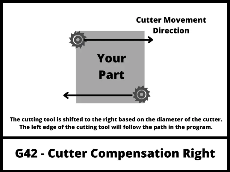
G42 is a modal command called cutter compensation right.

This code adjusts the path of the cutting tool based on the diameter of the cutter.

If you are looking towards the direction that the cutter is moving, the tool path is shifted to the right.

There are also codes for using no cutter compensation (G40) as well as using cutter compensation left (G41).

Ready to master CNC programming?

Try the free 30 minute intro course to see how simple and easy G code can be. Take the shortcut to becoming a G Code Master today!
What is cutter compensation?

illustration that shows how a CNC will act when using cutter compensation right with the G42 code

Cutter compensation is a CNC mode that allows the CNC controller to adjust for the size of the cutting tool.

Setting the size of the cutting tool allows you to use the same program with multiple different cutting tools.

Turning cutter compensation on tells the machine to shift the cutting tool either left with G41 or right with G42. The shift is half of the diameter of cutting tool, otherwise known as the radius.

Visualizing which way the machine will shift can be a little tricky. The shift happens as if you are looking towards the direction that the cutter is moving.

G41 vs G42

There are two different cutter compensation modes that can be used:

The direction of the shift is relative to the cutting tools direction of movement.

G41 is used when climb milling, which is the most common type of milling used.

G42 is used when conventional milling. Conventional milling sounds like it would be the standard but in reality, it is rarely used.

When climb milling, the cutter moves in the same direction as the stock feeds, which means that the workpiece produces less resistance to the cutting as the chips fall behind the cutter.

This type of milling helps prolong the life of the cutters and creates a better surface finish. This is the most commonly used milling method CNC machines.

On the other hand, with conventional milling the cutter runs in the opposite direction of the stock feed, which means that the cutter will have more resistance against the workpiece and cause more tool wear resulting in a shorter tool life.

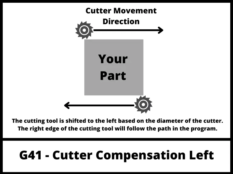
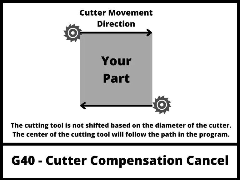
The two images below show how the CNC will move when the other cutter compensation modes are active.

illustration that shows how a CNC will act when using cutter compensation left with the G41 code
illustration that shows how a CNC will act when there is no cutter compensation mode active
How the CNC will move when cutter compensation is off

Advantage of using cutter compensation

The advantage of cutter compensation is that you won’t need to rewrite your program continuously to adjust for the size of your tool.

Imagine you bought a new end mill, and it came in 0.001” smaller than the last one. This would mean that your parts would now come out larger than before. To account for this you can use cutter compensation and your D offsets to tell the machine how big the cutter is.

This allows you to continue using the same program even though your cutter has changed.

Cutter sizes and D offsets

Even if you were to buy two of the same cutters, it is likely that there is a small difference in size between them. This difference in size is accounted for using offsets.

There are H offsets and D offsets that can be used when CNC machining.

illustration of a cnc cutting tool that shows what an D offset is

Because we are talking about cutter compensation with G42, we are going to focus on D offsets.

D offsets are stored in your machine’s controller, and they store the diameter of your cutting tool.

Now usually when the machine reads the coordinates given in the program, it moves the center of the cutting tool to that position. This can make it difficult to get the correct size especially when using different or multiple cutters.

Telling the machine the size of the cutters with your D offsets allows it to account for them and run the same program with different tools and get the same size part.

If you didn’t have cutter compensation, then you would need to create a new version of the program every time you wanted to use a new tool.

Using Tool Offset Table for Cutter compensation

mach 3 tool offset table

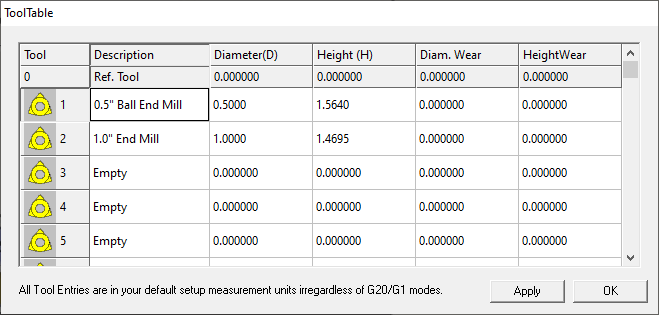
The Tool Offset Table, sometimes called Tool Table or Offset Library, is simply a table that the operator uses to store the offset values. This can include both diameter (D) and tool length (H) offsets.

Tool offset tables vary and some machines will only store one type of offset.

This means you may need to store both your diameter and tool length offsets in a D offset.

Some other machines may allow you to store the diameter and length of a cutting tool in the same offset number. The setup varies by machine so check yours out to make sure you know how it works.

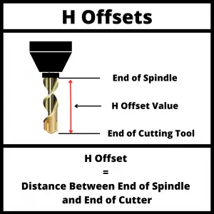
The purpose of the Tool Table is to tell the CNC machine what the dimensions of the cutting tool are. This includes radius and length.

How to turn off cutter compensation

Cutter compensation with G42 is canceled by using the G40 code which cancels all active cutter compensation modes.

Alternatively, G42 can be canceled by switching to cutter compensation right by using the G41 code.

The two main things to pay attention to when using G40 to cancel cutter compensation are:

  • Cancel cutter comp when you are off the part more than half the diameter of the cutter
  • Make a move when canceling cutter compensation

Canceling off the part enough keeps the machine from running back into the part.

Making a move forces the machine to move in a consistent way. Some machines can react unexpectedly if no move is made when canceling cutter compensation. The machine basically thinks it has teleported location.

Don’t teleport your CNC. Make a move when canceling cutter compensation.

G42 programming format

There are multiple ways of formatting a G42 command:

  1. G42 D1. When the G42 code is used with a D offset it is meant to be used on a machine with a built-in tool table in the controller. G42 turns on cutter compensation left and D1 tells the machine to adjust the tool path based on the size stored in the first D offset.
  2. G42 P2. The P value is the radius of the tool used in the operation. This format is used more often on hobby level machines.
  3. G42 X2. This format is the same as using the P value.

Focus on learning the first format unless you plan to only ever use simple home level machines.

Other types of compensation

The other main form of compensation is tool length compensation.

Tool length compensation is turned on with either G43 or G44. Although G44 is almost never used. G43 is by a super wide margin the most often used tool length compensation.

Tool length compensation accounts for the length of the cutting tool relative to the end of the spindle.

Tool length compensation is canceled with the G49 code.

Ready to master CNC programming?

Try the free 30 minute intro course to see how simple and easy G code can be. Take the shortcut to becoming a G Code Master today!

G84 CNC Code Explained: An Easy Intro for Beginners [Tapping]

What is a G84 CNC code?

A G84 command activates the tapping canned cycle.

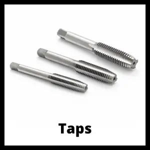
Tapping is threading the female portion of a mating pair. Basically, this means you are creating the thing that will be screwed into.

three different taps used for creating internal threads with a CNC machine

Tapping is done by rotating the spindle, which holds the tap, down through the hole until it reaches the desired depth (bottom of the hole).

Once at the bottom of the hole, the spindle will change directions and reverse out of the hole.

The G84 code is also used for peck tapping.

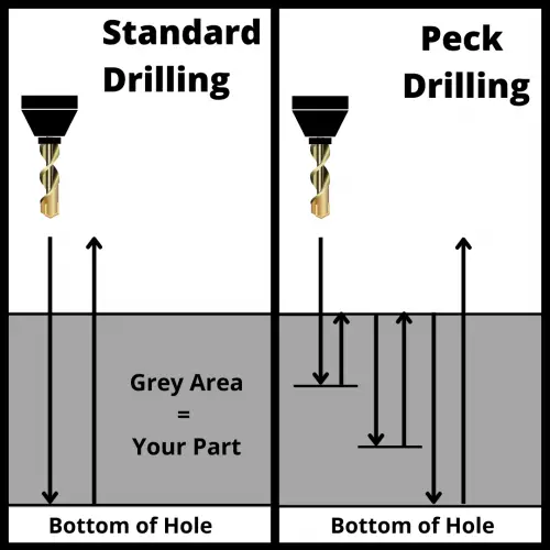
Peck tapping is similar to peck drilling where the machine will tap in steps. 

illustration that shows the difference between peck drilling and standard drilling in a CNC machine

For instance, if your peck depth was 0.1” then the machine would feed down 0.1” and then back up. Then the machine would feed down to 0.2” and back up. Rinse and repeat going 0.1” lower with each peck.

Ready to master CNC programming?

Try the free 30 minute intro course to see how simple and easy G code can be. Take the shortcut to becoming a G Code Master today!
When to use a G84 code?

The G84 code is used when you want to tap (thread) an existing hole in a part.

Never use the G84 command to drill a hole.

This operation is only meant to remove the material that will form the threads of the holes, not create the hole as well.

Other codes used with the G84 code

When using a G84 code you need to consider all the aspects that control the tapping process, these are:

The retracting value (R) or clearance level refers to the plane perpendicular to the Z-axis where the tool can move safely from one hole to another.

The R value should be set so the machine will clear any and all obstacles including clamps, fixtures and the part itself.

G84 code format

The format for using a G84 command is shown below:

G98 (or G99) G84 X2.0 Y3.0 R1.0 Z-5.0 F25.0

It would be easy to assume that the Z location is the location of the start of the hole. In reality, it is the Z location for the bottom of the hole tapping movement.

Keep in mind that the X and Y coordinates of the hole are not usually in the same line as the G84 command.

In most programs you will see them in this format:

X2.0 Y3.0
G98 G84 R1.0 Z-5.0 F25.0

The program first identifies the coordinates of the hole and then starts the tapping process.

How to cancel a G84 code?

The G84 code is canceled with the G80 command.  

If the G84 code is not canceled, the machine will try to tap a hole at every new location given in the program.

The G80 command cancels all canned cycles.

What to think about when using a G84 code?

Retract planes

visualization of how a cnc machine moves using g98 and g99 codes shows motion of travel for the machine

The G84 command is usually followed by G98 in the same line of code, in which case the machine will use the Z coordinate (height of the first hole) to move between holes. Keeping in mind this aspect can prevent redundant coding and machining errors.

When tapping it is advisable to set your R plane higher than usual.

CNC machines are capable of switching between modes very quickly, but the change is not instantaneous. 

The higher R plane gives the machine time to stabilize and ensure it is working at the correct feedrate before starting the cut.

Speeds and feeds

You will need to set the spindle speed before using the G84 cycle. 

When using G84, the spindle should always be moving clockwise through the use of an M03 command.

The feed rate of code G84 will be the pitch of your thread.

Various holds or overrides for speeds and feeds will not work when tapping. This is for safety purposes.

Hole size and location

Before using the G84 there must be a previous drilling cycle.

The correct hole diameter for a tapping operation will be the final diameter of the screw minus the pitch. For example, the diameter of the hole for an M10 x 1.5 mm hole will be 8.5 mm.

Keep in mind that the X and Y coordinates of the hole are not usually in the same line as the G84 command. The standard format for selecting your hole location and calling the G84 tapping cycle is shown below:

X50.0 Y50.0
G84 Z-40.0 R5.0 F20

The machine is moved to the location of the hole to be threaded and then the hole cycle is used.

G84 rigid tapping

Rigid tapping means that the tap can remain rigid throughout the cycle. The machine spindle locks in with the feedrate similar to the screw cutting process.

There are tapping heads specially designed for this process.

To perform Rigid Tapping, the machine should be able to synchronize feed motion and spindle speed. 

This option may not be available on all machines, especially older ones.

Check your machine manual to make sure you are capable of rigid tapping.

However, Rigid Tapping mode can cause issues due to chips sticking to the tool or increased cutting resistance. That’s why it is important to consider peck tapping.

G84 peck tapping

Including the Q code in the G84 command line will immediately set the machine to a peck tapping cycle.

This means that the spindle will rotate to a specified depth (Q value) in each tapping peck and then repeat the process, one step or “peck” at a time until reaching the bottom of the hole.

Peck tapping allows chips to exit the hole, making the tapping process easier and safer. 

The downfall of peck tapping is that it increases machining time when compared to standard tapping.  

The picture below is for drilling but it is the same concept. The pecks do not need to come all the way back up either.

You can drill down 0.200″ and then retract 0.100″ and then repeat the process going down 0.100″ at a time.

illustration that shows the difference between peck drilling and standard drilling in a CNC machine

G84 vs G74

The G74 cycle is the left-hand tapping cycle, sometimes called the reverse tapping cycle.

It performs the same operation as the G84 command but with the difference that the spindle rotates counterclockwise instead of clockwise.

The G74 left hand tapping cycle creates left hand internal threads while the G84 canned cycle creates standard or right-hand internal threads. Left hand threads are the opposite of your standard threads.

If G84 creates threads that are lefty-loosey, righty tighty then G74 creates threads that are righty-loosey, lefty tighty. In other words, G74 creates threads that would be screwed in the opposite way of normal.

The G74 command also has the ability to peck tap.

Both the G74 and G84 commands are modal commands which means they will stay on and in effect until they are either changed or canceled.

The cancel command to use with both cycles is the G80 code.

Ready to master CNC programming?

Try the free 30 minute intro course to see how simple and easy G code can be. Take the shortcut to becoming a G Code Master today!
G86 CNC Code Explained: An Easy Intro for Beginners [Boring with Rapid Retract]

What does a G86 code do?

The G86 command activates a boring canned cycle.

The steps the machine will take are:

  1. Rapid traverse to the R plane
  2. The machine will start boring/reaming from the R plane to the bottom of the hole (Z) at the listed feedrate (F)
  3. At the bottom of the hole, the spindle will stop and then the machine will rapid move back out of the hole.

This cycle will feed into the hole at a set feedrate but move at max speed coming back out.

The G86 canned cycle is very similar to G85 command except G85 will make the machine feed back out of the hole instead of rapid retract.

Ready to master CNC programming?

Try the free 30 minute intro course to see how simple and easy G code can be. Take the shortcut to becoming a G Code Master today!
What is boring?

Boring uses a single point cutting tool to create holes very accurately. This includes size, location and roundness requirements.

Boring involves creating a hole either by drilling it or some other means and then making it larger through the boring operation. Often this will require taking multiple passes to “sneak up” on the correct size requirements.

Other codes used with the G86 code

There are many different parameters used in a G86 code. They are similar to those used in other canned cycles. 

See the list below to understand all the different parts of the code.

The retracting value (R) or clearance level refers to the plane perpendicular to the Z-axis where the tool can move safely from one hole to another. 

The R value should be set so the machine will clear any and all obstacles including clamps, fixtures and the part itself.

Format for using a G86 code

G86 X2.0 Y3.0 R1.0 Z-5.0 F25.0

It would be easy to assume that the Z location is the location of the start of the hole. In reality, it is the Z location for the bottom of the boring/reaming movement.

Keep in mind that the X and Y coordinates of the hole are not usually in the same line as the G86 command.

In most programs you will see them in this format:

X2.0 Y3.0
G98 G86 R1.0 Z-5.0 F25.0

The program first identifies the coordinates of the hole and then starts the boring/reaming process.

How to cancel a G86 code

The G80 code is used to cancel the G86 boring canned cycle.

G80 is the code used to cancel all canned cycles.

If the G80 code is not used, the machine will attempt to bore a hole at each new location given in the program.

G85 vs G86

G85 and G86 are both boring canned cycles. They both move into the part at the set feedrate.

The G85 code will tell the CNC to feed back out at that same feedrate.

G86 stops the spindle and rapid retracts back out of the hole.

This means that G85 usually provides a better surface finish for the hole being machined, but takes more machining time.

R planes

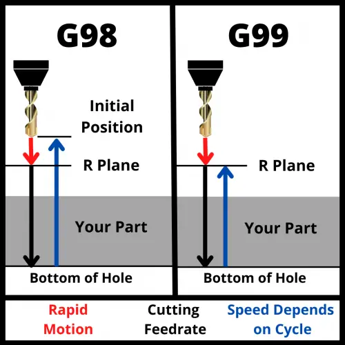
The G98 and G99 codes control what position your machine will return to after finishing a canned cycle. 

The G86 code is most commonly used with the G98 code. 

Retract planes are important because they control how your machine will act when moving between locations when using canned cycles such as G86.

visualization of how a cnc machine moves using g98 and g99 codes shows motion of travel for the machine
G98 and G99 – canned cycle return comparison

Retract planes should be chosen so that the machine avoids any and all obstacles such as clamps, fixtures and the workpiece itself. 

Ready to master CNC programming?

Try the free 30 minute intro course to see how simple and easy G code can be. Take the shortcut to becoming a G Code Master today!
M97 CNC Code Explained: An Easy Intro for Beginners [Subprogram Call by Line]

What does the M97 code do?

The M97 CNC code is a subprogram call by line number.

This means that the machine will run a subprogram contained within the main program.

The machine will jump to the line number in the current program that is called out with the M97 code.

At the end of the subprogram, the M99 code will be used. This signifies the end of the subprogram.

Once the machine reads the M99 code, it will return to the line in the program after the initial M97 code.

illustration that shows the flow of a cnc program when using the m97 command to call a subprogram

Ready to master CNC programming?

Try the free 30 minute intro course to see how simple and easy G code can be. Take the shortcut to becoming a G Code Master today!
Other codes used with the M97 code

Format for using an M97 code

Here is an example of an M97 code in use:

M97 P1234 L5

This line of code will tell the machine to move to line N1234 of the current program. 

The L code tells the CNC machine to run the subprogram five times. 

The L code can be left out if the subprogram will only be run once.

Line 1234 will be after the program end command (M30).

Once the machine reaches the M99 code it will return to the line after the example shown above.

What are subprograms used for?

Subprograms are a separate CNC program selected to run from within another program.

They are used to perform repetitive machining operations or sequences such as drilling, counterboring and countersinking a hole. 

They can also be used for machine related functions such as preparing for a tool change.

CNC machines run the lines of code in a program in order. 

Using subprograms allows the programmer to jump around to different sections of the current program or to run a different program and come back to the current program.

Differences between a subprogram and the main program

The commands to end the main program and a subprogram are different.

The main CNC program ends with either M30 code (for most machines) or M02 (for older machines). No further code will be run after either of these codes.

A subprogram ends with the M99 command

When using the M97 command, M99 returns the machine to the line which called the subprogram. The machine will continue to run code in the program from that point.

Let’s look at that program flow again to see how the machine moves from the subprogram call (M97) to the subprogram and back to the main program after the M99 code.

illustration that shows the flow of a cnc program when using the m97 command to call a subprogram

Benefits of using a subprogram

The greatest benefit of using subprograms is reducing the lines of code which makes the program easier to read and edit.

Subprograms can also reduce the number of errors in the program. Less lines of code means less possible sources of problems.

Drawbacks to using a subprogram

Subprograms are meant to make the program easier to work with for both the programmer and anyone using it. If not done correctly, they can have the opposite effect.

Programmers should remember that part of their job is making sure that the program is easy to use for the operator.

It can also be easy to have the wrong modal commands or offsets chosen when starting or ending a subprogram. 

Following a good program format that uses safety lines or blocks of code can protect from this happening.

If it is important that a mode or offset is needed in a specific section of your program, it is best to use the necessary code to make sure things are set correctly. 

Assuming your machine is in the correct mode already is dangerous. Set the correct modes when you need them.

Making subprograms inside your subprograms (nesting) also has the potential to cause confusion. Repeatedly switching between programs can be confusing for both programmers and operators.

M97 vs M98

There are two ways to run subprograms: M97 and M98.

The difference between M97 and M98 is the program location they move to.

M97 will jump to a new line in the current program.

M98 will run an entirely different program.

M98 Code Flow

Frequently asked questions about the M97 code

How do modal commands work in subprograms?

Modal commands work the same way as they do in the main program. This means they stay on until changed or turned off.

If a modal command is on when starting the subprogram, it will stay on while running the subprogram. The same is true when switching from the subprogram to the main program.

The safest thing to do is make sure your safety blocks cover the required codes for each section of code.

Ready to master CNC programming?

Try the free 30 minute intro course to see how simple and easy G code can be. Take the shortcut to becoming a G Code Master today!
M99 CNC Code Explained: An Easy Intro for Beginners [Subprogram End]

What does the M99 code do?

The M99 CNC code ends the current subprogram.

Once the machine reads the M99 code, it will return to the line in the program after the subprogram was called up.

If the subprogram was started using M97 (subprogram call by line number) then the machine will return to the line in the current program just after the M97 code.

If the subprogram was started using M98 (subprogram call by program number) then the machine will return to the line in the original program just after the M98 code was used.

Ready to master CNC programming?

Try the free 30 minute intro course to see how simple and easy G code can be. Take the shortcut to becoming a G Code Master today!
Other codes used with the M99 code

M97 vs M98

There are two ways to run subprograms: M97 and M98.

The difference between M97 and M98 is the program location they move to.

M97 will jump to a new line in the current program.

illustration that shows the flow of a cnc program when using the m97 command to call a subprogram

M98 will run an entirely different program.

M98 Code Flow

What are subprograms used for?

Subprograms are a separate CNC program selected to run from within another program.

They are used to perform repetitive machining operations or sequences such as drilling, counterboring and countersinking a hole. 

They can also be used for machine related functions such as preparing for a tool change.

CNC machines run the lines of code in a program in order. 

Using subprograms allows the programmer to jump around to different sections of the current program or to run a different program and come back to the current program.

Differences between a subprogram and the main program

The commands to end the main program and a subprogram are different.

The main CNC program ends with either M30 code (for most machines) or M02 (for older machines). No further code will be run after either of these codes.

A subprogram ends with the M99 command. 

It doesn’t matter if you use the M97 or M98 command to call your subprogram, M99 will return the machine to the next line in the original program after the M97 or M98 code was used. 

The machine will continue to run code in the program from that point.

If an M30 code is used to end a subprogram then the machine will stop running. It will not return to the line after the subprogram call like it would when using the M99 command.

Benefits of using a subprogram

The greatest benefit of using subprograms is reducing the lines of code which makes the program easier to read and edit.

Subprograms can also reduce the number of errors in the program. Less lines of code means less possible sources of problems.

Drawbacks to using a subprogram

Subprograms are meant to make the program easier to work with for both the programmer and anyone using it. If not done correctly, they can have the opposite effect.

Programmers should remember that part of their job is making sure that the program is easy to use for the operator.

It can also be easy to have the wrong modal commands or offsets chosen when starting or ending a subprogram. Following a good program format that uses safety lines or blocks of code can protect from this happening.

If it is important that a mode or offset is needed in a specific section of your program, it is best to use the necessary code to make sure things are set correctly. 

Assuming your machine is in the correct mode already is dangerous.

Making subprograms inside your subprograms (nesting) also has the potential to cause confusion. Repeatedly switching between programs can be confusing for both programmers and operators.

For a more in-depth description of subprogram nesting, see additional info on the topic further down in this post.

Frequently asked questions about the M99 code

How do modal commands work in subprograms?

Modal commands work the same way as they do in the main program. This means they stay on until changed or turned off.

If a modal command is on when starting the subprogram, it will stay on while running the subprogram. The same is true when switching from the subprogram to the main program.

The safest thing to do is make sure your safety blocks cover the required codes for each section of code.

What is nesting

So far, we have concentrated on running a subprogram from our main program, but did you know you can also run a subprogram from within a subprogram?

This is called nesting.

Nesting can be a powerful tool but can quickly get out of control. 

Most CNC controllers will allow up to four level deep nesting. This means calling a subprogram in a subprogram in a subprogram in a subprogram in your main program.

Confusing right? That is why in most cases it isn’t a good idea to nest that deep. For most applications, one level deep is enough.

Even two level nesting can be hard to follow. Three and four levels are definitely not advised if you are reading this post which is aimed at beginners.

Ready to master CNC programming?

Try the free 30 minute intro course to see how simple and easy G code can be. Take the shortcut to becoming a G Code Master today!
N CNC Code Explained: An Easy Intro for Beginners [Program Line Number]

What does the N CNC code do?

N codes are used in a CNC program to identify the block or line of the program.

In most programs, the blocks increase by 5 or 10 on each line. This allows you to add lines in between if the program needs to be edited.

N codes are not required.

They can be left out entirely if the programmer chooses to do so.

Some example N code sequences are shown below:

Increment By

N Code Sequence

1

N01

N02

N03

N04

N05

5

N05

N10

N15

N20

N25

10

N10

N20

N30

N40

N50

Where does the N code show up in the CNC program?

If they are used, generally N codes will show up at the beginning of each block and typically run through the entire program.

There are some programmers who chose to only use line numbers (N codes) on important lines such as the start of a new tool.

Why are N codes used?

N codes help the programmer follow along with the program. 

This is especially true for new programmers.

Identifying each line of code with a sequence (N) number makes it easier to find or modify different sections of the program.

Ready to master CNC programming?

Try the free 30 minute intro course to see how simple and easy G code can be. Take the shortcut to becoming a G Code Master today!
Drawbacks to using N codes

Using N codes throughout your program does make the program file size larger because it contains more characters. 

This is more of a problem for older machines with very limited memory.

Format for using an N code

The N-code should be the first thing on every block (line) of the program.

This is how it looks in practice:

N10 G90 F100 S1200 T01.01
N20 G00 X36 Z10
N30 X26 Z2
N40 G01 Z-12 M03
N50 X36 M05
N60 G00 Z10
N70 M30

Notice how the N numbers jump up by 10 on each line.

If we needed to insert a couple more lines of code into the program it might end up looking like this:

N10 G90 F100 S1200 T01.01
N20 G00 X36 Z10
N30 X26 Z2
N34 Y20
N38 X40
N40 G01 Z-12 M03
N50 X36 M05
N60 G00 Z10
N70 M30

When editing the program we tried to keep the lines spaced out in case it needs to be edited again in the future. 

We could have numbered the new lines as N31 and N32 or N32 and N34. It really is up to the person editing the program. 

Good practice is to try and leave gaps in the numbers if possible.

Best way to number your N codes

The standard recommended format for numbering your lines of code is to increment by 5 or 10. 

This will leave spaces between each line in case the programmer needs to edit the program in the future.

N codes when using the M97 code

The M97 code is used for calling a subprogram by line number.

The format for using an M97 code is:

M97 P125

In this example, the machine will read the subprogram call and then jump to line N125 in the current program. 

Using the M97 command allows you to jump around your program.

When using subprograms with M97, the best practice is to put your subprogram lines at the very bottom of the program. 

Doing this will clearly separate your subprogram from the rest of the program.

When you use the M99 code to end a subprogram called with the M97 code, the machine will jump back to the next line after the M97 was used.

The picture below shows how the program flow works.

illustration that shows the flow of a cnc program when using the m97 command to call a subprogram

Frequently asked questions about N codes

Do you have to use sequence (N) numbers in your program?

No, sequence numbers with the N code are not required but they are highly recommended. 

Using them will make your program easier to read and follow.

Additionally, increasing the size of the program is less of an issue with newer machines than it was in years past.

Can you use a negative N number?

No, it is not possible to use negative numbers to identify the lines of a program.

Can you use a N number with a decimal point?

No, you will need to use whole numbers when using the N code.

What happens if my sequence (N) numbers are out of order?

The CNC will read them from top to bottom. 

If you sequence numbers are out of order such as:

N5
N20
N15
N10
N30

The machine will still read them in the order they are shown above. Unless you are using subprograms, the machine just ignores the sequence (N) numbers.

Ready to master CNC programming?

Try the free 30 minute intro course to see how simple and easy G code can be. Take the shortcut to becoming a G Code Master today!
O CNC Code Explained: An Easy Intro for Beginners [Program Number]

Welcome to the exciting world of CNC programming!

If you’re curious about the O CNC code and want to learn how to use it, you’ve come to the right place.

In this easy-to-follow guide, we’ll teach you everything you need to know. Don’t worry if you’re new to this, because the O code is super easy to learn.

So, let’s jump in to discover the O CNC code together!

What does the O code do?

The O code lists the CNC program number. 

It is found on the first line of a CNC program.

Example program numbers

Code BlockProgram Number
O00011
O12341234
O0555555

What range of numbers can you use with the O code?

Most controllers allow the use of program numbers O0001 through O9999.

Some newer machines allow a larger range of program numbers, but they would rarely be used or needed.

O code program example

Code BlockCode Description
O0001(Program number: O0001)
G90 G80(Absolute positioning mode, cancel canned cycles)
G54 G0 X0 Y0 (Select coordinate system G54, rapid move to X0 Y0)
M3 S1000(Start spindle clockwise at 1000 RPM)
G43 H1 Z0.1(Tool length compensation active, move Z to 0.1)
G1 Z-0.5 F100(Linear move to Z-0.5 at a feed rate of 100)
X1 Y1(Linear move to X1 Y1)
X0 Y0(Linear move back to X0 Y0)
G0 Z1(Rapid move to Z1, retracting the tool)
M30(End of program and rewind)

Ready to master CNC programming?

Try the free 30 minute intro course to see how simple and easy G code can be. Take the shortcut to becoming a G Code Master today!
Using the O code when running subprograms with M97 and M98

Subprograms are reusable pieces of code that are often used for repetitive tasks such as drilling holes or changing a tool.

There are two codes used to call subprograms; M97 & M98.

When using M98, the P code is used to choose the subprogram to be run.

For example, M98 P5678 will tell the CNC to run subprogram O5678.

M98 Code Flow

M98 calls a separate program.

The M97 code calls a subprogram by line number in the current program.

Important: M97 and M98 call subprograms differently. M97 jumps to another line in the current program. M98 moves to a completely separate program.

An example of this is M97 P500 will tell the machine to jump to line number 500 in the current program. The N code notes the line number.

illustration that shows the flow of a cnc program when using the m97 command to call a subprogram

Ready to master CNC programming?

Try the free 30 minute intro course to see how simple and easy G code can be. Take the shortcut to becoming a G Code Master today!

Q CNC Code Explained: An Easy Intro for Beginners [Peck Depth]

What does the Q CNC code do?

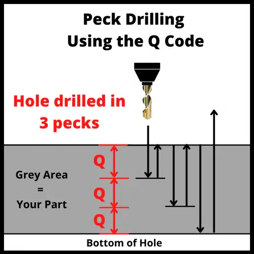
The Q code is used to specify the depth of each peck when peck drilling with either the G73 or G83 code.

The “peck” is how much farther down the machine will drill on each pass.

When peck drilling, the machine drills down, backs up, drills further down, backs up, drills even further down and repeats until the cycle has been completed.

Difference between peck and standard drilling

illustration that shows the difference between peck drilling and standard drilling in a CNC machine

The main difference between peck and standard drilling is that the peck drilling process removes the material in multiple steps, while standard drilling is a one-step process.

Both commands are intended to make holes, but the peck drilling cycle allows more control over how the hole is drilled.

Peck drilling is the first option for CNC programmers when making blind holes. The pecking process helps break chips as well as remove them and any other debris from the hole during the drilling process.

Trouble removing chips from the hole when drilling can cause size and/or surface finish issues.

Standard drilling is far more common when dealing with simple through (thru) holes.

Ready to master CNC programming?

Try the free 30 minute intro course to see how simple and easy G code can be. Take the shortcut to becoming a G Code Master today!

Types of peck drilling

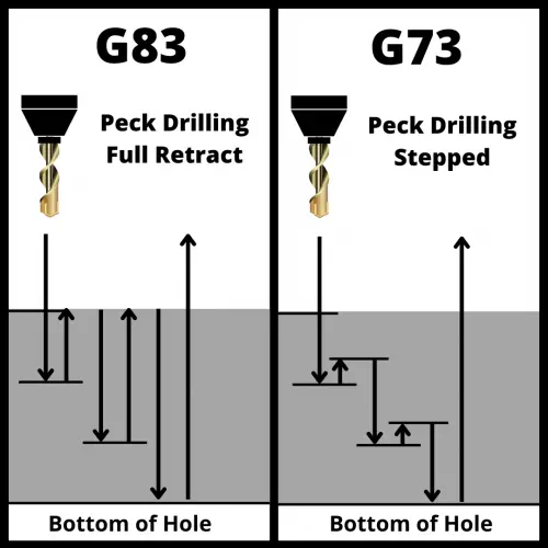
There are two peck drilling cycles, G73 and G83.

They are both canned cycles with one key difference. 

Using the G83 code will retract completely out of the hole after each peck to the retract plane. 

Using the G73 code will only retract to the start of each peck.

an illustration that shows the difference between the G73 and G83 CNC codes

The G73 canned cycle is a peck drilling cycle but with a shorter retract intended for relatively shallow holes. 

Meanwhile, the G83 command is peck drilling with a full retract intended for deep holes.

Both commands are meant to help break and clear chips. 

G83 does a better job of this by fully retracting out of the hole but with the added expense of a longer cycle time.

On the other hand, G73 is designed to break up stringy chips, while G83 is intended to pull chips up and out of deep holes.

Other codes used with the Q code

The Q code is used in peck drilling canned cycles G73 and G83. 

You can also expect to find the following codes used in those canned cycles:

Format for using the Q code

The format for using a Q code is shown below:

G98 G83 R1.0 Z-5.0 Q1.0 F25.0

This example shows a peck depth (Q) of 1.0.

This means that the machine will drill the hole in 1.0 unit steps. This would be 1 inch or 1mm depending on which unit mode you currently have active.

Ready to master CNC programming?

Try the free 30 minute intro course to see how simple and easy G code can be. Take the shortcut to becoming a G Code Master today!

R CNC Code Explained: An Easy Intro for Beginners [Multi Use Code]

What does the R CNC code do?

There are two main functions for the R code when CNC programming, radius size and setting the retract (R) plane.

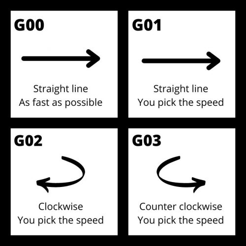
When combined with the G02 or G03 circular interpolation commands, the R code specifies the size of the radius to be machined.

When combined with canned cycles such as G73 through G89, the R code specifies the location of the R plane or clearance height to be used.

Radius size with G02 or G03

There are two types of circular movement (interpolation) that can be used when CNC machining.

They are G02 for clockwise movement and G03 for counterclockwise movement.

a comparison of the type of movement created with G00, G01, G02 and G03 cnc g codes

The format for using both codes is:

G02 (or G03) X10 Y15 R5 F30

The X and Y locations are the end point of the circular movement. 

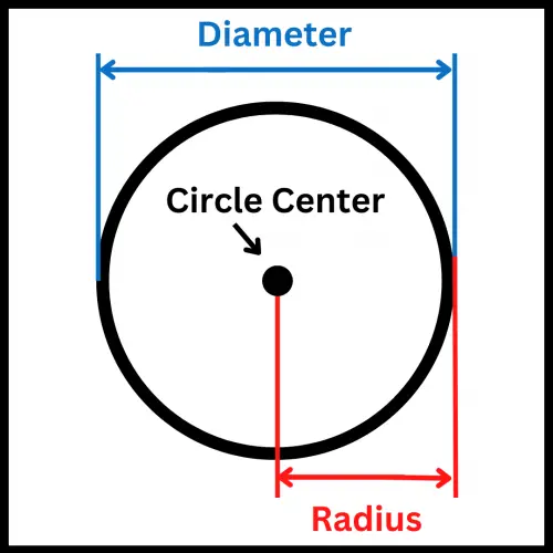
The R value is the radius size of the circle and F is the feedrate.

illustration that compares a circles radius and diameter

Circular movement can also be performed using IJK codes instead of XY locations and an R value.

Both methods are common, so be on the lookout for either type.

Ready to master CNC programming?

Try the free 30 minute intro course to see how simple and easy G code can be. Take the shortcut to becoming a G Code Master today!

R plane with canned cycles

The R plane is a specific height that the CNC will reference when performing a canned cycle.

First it is the height that the machine will rapid travel to and begin the machining part of the canned cycle.

It is also the height that the machine will return to if the G99 [return to R plane] command is active.

If the G99 [return to initial plane] command is active then the machine will return to the start of the canned cycle instead.

visualization of how a cnc machine moves using g98 and g99 codes shows motion of travel for the machine

The G98 and G99 codes are used to switch between the two types of clearance modes available when running canned cycles.

The G98 code moves the cutter further up and away because in most instances the canned cycle is started at a higher Z height location further away from the part. This increases the time that it takes the machine to run the program.

The G99 command is used to keep the machine closer to the part being machined. It should only be used when you are sure that there are no obstacles in the way such as the part itself, clamps or fixtures.

Format for using the R code with canned cycles

The format for using canned cycles is:

G81 X0 Y0 R5 Z1 F5 G98

G81 is the canned cycle. This can be replaced with any other canned cycle as needed.

The R code sets the retract plane height. 

The X, Y and F codes are not required. 

X and Y are the location where the canned cycle will be run. F is the feedrate of the cutter.

Often, the X and Y codes will be placed on the previous line.

It is good practice to include the feedrate (F) code.

Ready to master CNC programming?

Try the free 30 minute intro course to see how simple and easy G code can be. Take the shortcut to becoming a G Code Master today!