M98 CNC Code: Call a Subprogram from Your Main Program

M98 is the CNC code that calls a subprogram by program number. When the machine reads M98, it stops running the current program and jumps to a separate program stored on the controller. When that subprogram finishes, the machine returns to where it left off and keeps running.

Key Takeaways

  • M98 calls a separate CNC program (subprogram) by its program number
  • The subprogram must end with M99 — this sends the machine back to the main program
  • Use the P word to specify which program to call, and the L word to repeat it
  • Whether your machine uses L or K for repetitions depends on the controller — always check the manual
  • M98 calls an external subprogram; M97 jumps to a section inside the current program
M98 – At A Glance
FunctionSubprogram call by program number
FormatM98 P____
Repeat parameterL or K (depends on control)
Ends withM99 in the subprogram
TypeNon-modal

What Does M98 Do?

M98 tells the CNC machine to go run a different program. That other program is called a subprogram.

The machine jumps from the current line to the beginning of the subprogram. It runs every line in that subprogram. At the end of the subprogram, the M99 code sends the machine back to the line right after the M98 command. Then the main program continues as normal.

M98 Format and Parameters

Here is the basic format:

M98 P5678

This tells the machine to go run program number 5678 using the P code. When that program ends with M99, the machine comes back and picks up where it left off.

M98 Code Flow

You can also repeat the subprogram using the L word (or K word, depending on your machine):

M98 P5678 L3

This runs program O5678 three times before returning to the main program. If you leave out L, the subprogram runs once.

COMMON MISTAKE – L vs K for Repetitions

Some CNC controllers use L to set the number of repetitions. Others use K. Using the wrong one won’t always throw an alarm — the machine might just ignore it and run the subprogram once.

If your subprogram isn’t repeating like you expect, check your machine manual to confirm which word your control uses.

What Are Subprograms Used For?

Subprograms are used for any operation you need to repeat in a program. Common examples include drilling patterns, tool change routines, and finishing passes that happen at multiple locations.

Using subprograms keeps your main program short and easier to read. If something needs to change — like a feed rate or depth — you fix it in one place instead of hunting through dozens of repeated lines.

Benefits of Using Subprograms

The biggest benefit is a shorter, cleaner main program. Fewer lines means fewer places for errors. It also means less editing if something needs to change later.

Subprograms are especially useful when a machining sequence repeats at many locations across a part. Think of bolt hole patterns, pockets at multiple heights, or standard deburring passes.

Drawbacks to Watch Out For

Subprograms can backfire if they’re not set up carefully. The most common issue is modal commands carrying over in ways you didn’t expect. If the subprogram leaves the machine in the wrong mode — like incremental positioning or an active canned cycle — the main program can behave unpredictably when it resumes.

Use safety blocks at the start and end of subprograms to confirm the machine is in the state you expect. Don’t assume the mode is correct — set it explicitly.

Nesting subprograms (calling a subprogram from within a subprogram) is another potential issue, mostly because it can quickly get complicated. Most controllers allow up to four levels of nesting, but even two levels can get confusing fast. For most applications, one level deep is enough.

A Real Example: M98 in a Program

Here is what M98 looks like inside an actual program. The main program calls a subprogram to drill a hole pattern at two different locations.

Main program (O0100):

O0100
G90 G54 G00 X0.0 Y0.0     (Move to first location)
M98 P5001 L3               (Run subprogram 5001 three times)
G00 X5.0 Y0.0              (Move to second location)
M98 P5001 L3               (Run subprogram 5001 three times again)
M30                        (End of main program)

Subprogram (O5001):

O5001
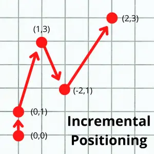
G91 G81 Z-1.0 R0.1 F8.0   (Drill one hole in incremental mode)
X1.0                       (Step over and drill again)
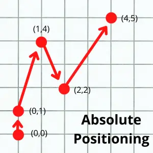
G90 G80                    (Cancel canned cycle, back to absolute)
M99                        (Return to main program)

Each time the main program calls O5001, the machine drills two holes and comes back. Instead of writing that drilling sequence six times, you write it once and call it as needed.

Differences Between the Main Program and a Subprogram

The main program ends with M30 (or M02 on older machines). The subprogram ends with M99.

When M99 runs, the machine returns to the line right after the M98 call in the main program. The main program then continues from that point. Nothing is reset automatically — whatever modal codes were active when you called the subprogram are still active when you return.

M97 vs M98

There are two codes you can use to call a subprogram, M97 and M98. The difference is where they look.

M97 jumps to a line number inside the current program. The subprogram is embedded right there in the same file.

illustration that shows the flow of a cnc program when using the m97 command to call a subprogram

M98 runs a completely separate program stored on the machine. Use M98 when the subprogram is something you want to reuse across multiple main programs.

Tips for Numbering Your Subprograms

Set up a numbering system before you have too many programs to keep track of. Some shops reserve a block of numbers for subprograms — for example, O0001–O4999 for main programs and O5000–O9999 for subprograms.

Another common approach is to number subprograms close to their parent program. If the main program is O1000, its subprograms are O1001, O1002, and so on. This makes it easy to find everything related to a job.

FAQS

What happens to modal codes when M98 calls a subprogram?

Modal codes stay active across the subprogram call. If G91 (incremental mode) is active when M98 runs, the subprogram starts in incremental mode.

If the subprogram changes a modal code and doesn’t reset it, that change carries back to the main program when M99 runs. Always end your subprograms with safety blocks to confirm the machine state.

Can I call M98 inside a subprogram?

Yes — this is called nesting. Most controllers support up to four levels of nesting. That means a subprogram can call another subprogram, which can call another, and so on.

In practice, one level is usually enough. Deep nesting is hard to troubleshoot and easy to lose track of.

Do I need to store the subprogram on the same device as the main program?

Yes. For M98 to work, the subprogram called by the P word must already be stored in the controller’s memory. The exact requirements depend on your specific machine and control (Fanuc, Haas, Mazak, etc.). Check the manual if you get a program-not-found alarm.

What is the difference between M98 and M97?

M97 jumps to a line number inside the current program. M98 calls a completely separate program by its O number. Use M97 when the subprogram is short and only used by that one main program. Use M98 when the subprogram is reused across multiple jobs.

M03 G-Code: Turn the Spindle On (Clockwise) — CNC Basics

What Does M03 Do?

M03 turns the CNC spindle on in a clockwise direction. That’s it — one command, one job.

On a CNC mill, clockwise rotation is the standard for right-hand cutting tools. Right-hand tooling is what you’ll use in almost every situation. So M03 is probably the most common spindle command you’ll ever write.

Key Takeaways

  • M03 starts the spindle in a clockwise direction (right-hand tooling)
  • Always pair it with an S code to set spindle speed — or make sure speed is already set
  • M03 stays on until you cancel it with M05
  • Use M04 for counterclockwise rotation (left-hand tooling)
  • Stop the spindle before changing direction — never switch M03 to M04 mid-program without M05 first
M03 – At A Glance
FunctionSpindle On — Clockwise
FormatM03 or M3
TypeModal
Cancelled byM05
Used withUsed with
ToolingRight-hand (standard)

Setting Spindle Speed with M03

M03 is almost always programmed with an S code. The S code sets the spindle speed in RPM. You can write them on the same line or on separate lines — the machine doesn’t care.

Same line:

S1000 M03

Separate lines:

S1000
M03

Both do the same thing. The spindle will turn on at 1,000 RPM.

If you write M03 without an S code, the machine uses whatever speed was set last. That might be fine — but it’s risky if you’re not sure what’s still in memory. The safer habit is to always set the speed explicitly.

M3 vs M03 — Is the Zero Required?

No. M3 and M03 are identical to the CNC controller.

The zero is just a formatting preference. Textbooks and reference materials tend to show the full M03. In real shop programs, you’ll often see the shorter M3. Either works.

If you’re programming on your own, pick one and be consistent. If you’re in a shop with existing programs, match their format.

M03 vs M04 — Which Direction?

There are two codes that turn the spindle on:

  • M03 — Clockwise. Used with right-hand tooling.
  • M04 — Counterclockwise. Used with left-hand tooling.
Spindle direction

Right-hand tools are the standard. Most mills, drills, and end mills are right-hand cut. You’ll use M03 the vast majority of the time.

M04 shows up occasionally — tapping with left-hand taps, some specialized operations, or certain lathe work. But for everyday milling and drilling, M03 is your go-to.

COMMON MISTAKE – Changing Directions

Never switch directly from M03 to M04 (or vice versa) without stopping the spindle first. Always use M05 between them.

Changing direction while the spindle is still spinning puts stress on the drive and can cause a fault or damage. Stop it, then restart in the new direction.

Turning the Spindle Off — M05

M05 is the spindle stop command. It works no matter which direction the spindle is turning.

If you started with M03, you stop with M05. Same if you started with M04. One command stops both.

Always use M05 before a tool change, before the program ends, and before you change spindle direction.

M03 Example Program

Here’s a simple drilling program using M03 to turn the spindle on before drilling a series of holes with the G81 canned cycle:

O0001                            (Program number)
G90 G54 G17 G40 G49 G80         (Safety line — absolute mode, work offset, cancel comp)
T01 M06                          (Tool change — Drill)
S1200 M03                        (Spindle on clockwise at 1200 RPM)
G43 H01 Z1.0                     (Tool length compensation on)
G00 X1.0 Y1.0                    (Rapid to first hole)
G81 Z-0.75 R0.1 F8.0             (Drill canned cycle)
X2.0                             (Next hole)
X3.0                             (Next hole)
G80                              (Cancel canned cycle)
G00 Z5.0                         (Retract)
M05                              (Spindle off)
M30                              (End program, rewind)

Notice that S1200 M03 appears before the rapid move and canned cycle. The spindle is running before the tool ever gets close to the part.

Other CNC codes to know when working with M03

When you’re writing programs that use M03, you’ll frequently see these codes nearby:

  • S — Sets spindle speed in RPM. Used on the same line or just before M03.
  • M04 — Counterclockwise spindle. The opposite of M03.
  • M05 — Spindle stop.
  • G96 — Constant surface speed mode (mainly on lathes). Tells the machine to maintain a set surface speed, automatically adjusting RPM as the diameter changes.
  • G97 — Constant RPM mode. Locks the spindle at a specific RPM regardless of diameter. This is the default mode on most mills.

FAQS

Does M03 automatically set the spindle speed?

No. M03 only starts the spindle — it doesn’t set the speed. You need an S code to define the RPM. If no S code is given, the machine uses the last speed in memory, which may or may not be correct.

What happens if I forget M05 and the program ends?

On most modern CNC machines, M30 (program end) or M02 will stop the spindle automatically. But it’s still good practice to include M05 explicitly — it makes the program easier to read and doesn’t rely on the controller doing cleanup for you.

Can I use M03 on a CNC lathe?

Yes. M03 works on lathes too. On a lathe, clockwise typically means the spindle rotates so the cutting tool engages the outside diameter correctly for right-hand turning tools. Check your machine’s documentation to confirm the rotation direction for your specific setup.

What’s the difference between M03 and G97 M03?

G97 puts the machine in constant RPM mode — meaning the S code sets a fixed RPM. When you write G97 S1000 M03, the spindle turns on at exactly 1,000 RPM. On lathes, you’d use G96 for constant surface speed mode instead, but mills almost always run G97.

G83 G-Code: Peck Drilling Cycle Explained

What is a G83 CNC code?

G83 is a CNC canned cycle for peck drilling. It drills a hole in a series of steps called pecks, retracting fully out of the hole after each one.

That full retract is the key difference between G83 and other drilling cycles. Pulling the tool completely out gives chips a clean path to escape and lets coolant flush the hole before the next pass.

G83 is a modal command, meaning it stays active until you cancel it with G80.

Key Takeaways

  • G83 drills in steps (pecks), retracting fully to the R plane or initial point after each one
  • Use it when hole depth is 3–4 times the drill diameter or greater
  • Q sets the peck depth — typically no larger than the drill’s diameter
  • Cancel it with G80 when you’re done drilling, or the machine will keep drilling at every XY position in the program
  • G73 is the faster alternative — use it for shallower holes where full chip clearance isn’t needed
G83 – At A Glance
FunctionPeck drilling canned cycle
TypeModal (Group 9)
Cancelled byG80
Returns toG98: initial point / G99: R plane
Key parameterQ — peck depth per pass
Use whenHole depth is 3–4× greater than diameter

Peck Drilling vs. Standard Drilling

Standard drilling (G81) pushes straight to depth in one pass. That works fine for shallow holes in most materials. Peck drilling breaks that depth into steps.

illustration that shows the difference between peck drilling and standard drilling in a CNC machine

Each peck drills a short distance, then the tool retracts. This breaks the chip, clears debris, and lets coolant into the hole. On deep holes, that makes a big difference in hole quality and tool life.

G83 is especially common for blind holes, where chips have nowhere to go except back up the drill flute. Helping them clear the hole prevents packing, which causes oversize holes and broken tools.

Other codes used with the G83 code

G83 code format

G98 G83 X__ Y__ R__ Z__ Q__ F__

Here is a breakdown of each address:

  • X and Y are the hole location
  • R is the clearance height above the part surface
  • Z is the final depth at the bottom of the hole
  • Q is how far the tool drills before retracting (peck depth)
  • F is the feedrate

In practice, you’ll usually see the XY position on its own line before the cycle line:

X2.0 Y3.0
G98 G83 R0.1 Z-1.5 Q0.25 F12.0

The program positions to the hole first, then triggers the drilling cycle. The Z value is the bottom of the hole — not the start.

G83 Example Program

G90 G54 G00 X1.0 Y1.0            (Rapid to first hole position)
G43 H01 Z1.0 M03 S1200           (Tool length comp, spindle on)
G98 G83 R0.1 Z-1.5 Q0.25 F12.0   (Start peck drilling cycle)
X2.0 Y1.0                         (Second hole — cycle repeats)
X3.0 Y1.0                         (Third hole)
G80                                (Cancel canned cycle)
G00 Z5.0 M05                      (Retract, spindle off)

G83 is modal, so after the first G83 line, all the XY moves repeat the cycle automatically. G80 cancels it.

When to Use G83

Use G83 when:

  • The hole depth is 3–4 times the drill diameter or more
  • You’re drilling blind holes and chip clearance is a concern
  • You want a clean finish on deep holes
  • You’re working in tough or stringy materials like stainless steel or titanium

A good general rule: if you’d use more than one peck to comfortably drill the hole manually on a drill press, use G83 on the CNC.

When Not to Use G83

Skip G83 for shallow through-holes in easy materials. Standard drilling with G81 is faster and perfectly fine when chip clearance isn’t a problem.

G83 has a longer cycle time because of the full retracts. If you’re drilling dozens of holes, that adds up. On shallower holes, G73 (partial retract) is often a better choice. 

What to Think About When Using G83

Peck Depth (Q)

Q controls how far the tool drills before it retracts. A larger Q value means fewer pecks and a faster cycle. A smaller Q value is gentler on the tool.

A common starting point is to set Q equal to the drill diameter. So a 0.250″ drill would start with Q0.25. Adjust from there based on material hardness and chip behavior.

Some CNC controls support variable peck depth — where each peck gets progressively shorter to avoid chip packing deeper in the hole. Check your machine manual if you want to use that feature.

Retract Planes

G98 and G99 control where the tool goes after each drilling cycle.

  • G98 returns to the Z height the tool was at when the cycle started (the initial point). Use this when there are clamps, fixtures, or raised features between holes.
  • G99 returns to the R plane only. It’s faster, but be certain the R plane clears everything in your path.
visualization of how a cnc machine moves using g98 and g99 codes shows motion of travel for the machine

If you’re not sure which to use, default to G98. The extra Z travel is worth the safety margin.

Positioning Mode

Check which positioning mode is active before running a G83 cycle.

The wrong mode can put the tool in a completely unexpected location. This is a common cause of machine crashes on drilling operations.

The difference between the two modes is shown below. 

graph paper example of absolute positioning with multiple points as examples
graph paper example of incremental positioning with multiple points as examples

When in absolute mode, the machine will move relative to a fixed zero location.

When in incremental mode, the machine will move relative its current location.

Look at the first move in the pictures above. They both start at (0,0). They both move up one block in the Y axis.

On the second move, in absolute mode the machine the machine is still reading the new location as from the fixed zero location. In incremental mode the move is from the machines current location which is why the move is 1 block shorter in the Y axis.

COMMON MISTAKE – Forgetting G80

If you don’t cancel G83 with G80, the machine treats every XY move after the cycle as a new hole location. It will drill wherever the program sends it next — including over clamps, into fixtures, or off the part entirely.

Always end your drilling section with G80.

How to Cancel G83

Use G80 to cancel G83 and all other canned cycles.

G80

Put G80 on its own line immediately after your last hole. Some programmers also include G80 at the start of a drilling section as a precaution, in case a previous program left a canned cycle active.

G83 vs G73

G73 and G83 are both peck drilling cycles. The difference is how far the tool retracts after each peck.

  • G83 fully retracts to the R plane or initial point after every peck — complete chip clearance, longer cycle time
  • G73 only pulls back a small amount (set by the machine parameter) — faster, but less effective at clearing chips

Use G83 for deep holes where full chip removal matters. Use G73 for shallower holes where you just need to break up chips without the full retract penalty.

an illustration that shows the difference between the G73 and G83 CNC codes
CodeRetractBest For
G83Full retract to R planeDeep holes, blind holes, tough materials
G73Partial retract onlyModerate depth, chip breaking without full clearance

G83 vs Other Drilling Cycles

Code

Name

Function

Simple through-holes, no peck

Drilling with dwell at bottom

Deep holes, full chip clearance

Moderate depth, faster cycle

G80 G-Code: How to Cancel a Canned Cycle (With Examples)

G80 cancels any active canned cycle on your CNC machine. Think of it as the off switch for drilling, tapping, and boring cycles.

Once a canned cycle is active, the machine will repeat that operation at every new position you program. G80 tells the controller to stop.

Key Takeaways

  • G80 cancels all active canned cycles
  • Without G80, the machine will keep drilling (or tapping) at every new move
  • G80 is commonly included in safety lines at the start of a program
  • G00, G01, G02, and G03 also cancel canned cycles — but relying on them for that is bad practice
  • Always cancel your canned cycle explicitly with G80 when you’re done
G80 – At A Glance
FunctionCanned Cycle Cancel
TypeModal (Group 9)
CancelsG73, G74, G76, G81, G82, G83, G84, G85, G86, G89

What are canned cycles?

Canned cycles — also called fixed cycles — are G-codes that automate common hole-making operations. Instead of programming every move individually, a single line of code handles the whole sequence.

Tasks like drilling, peck drilling, tapping, and boring all have their own canned cycle codes. A good example is peck drilling with G83.

Without a canned cycle, you’d need dozens of lines to move the drill up and down through a deep hole. With G83, one line handles it all.

Here’s the complete list of canned cycles G80 can cancel:

When to use G80

Use G80 any time you’re done running a canned cycle and need to move the machine without triggering another operation.

The most common situation: you’ve drilled a pattern of holes and now need to move on — to a tool change, a facing pass, or a repositioning move. Without G80, the machine will try to execute the active cycle at whatever coordinates you move to next.

G80 is also standard in program safety lines. Many shops include it at the top of every program alongside G40 and G49. This ensures no canned cycle was accidentally left active from a previous run.

Here’s what a typical safety line block looks like:

G40 G49 G80      (Cancel cutter comp, tool length comp, canned cycles)

If you ever restart a program mid-cycle — to re-run a section, for example — G80 in the safety lines guarantees the machine starts clean.

G80 Code Example

Here’s a practical example showing G80 used correctly after a drilling cycle:

T01 M06                          (Tool change — drill)
G90 G54 G00 X1.0 Y1.0            (Rapid to first hole)
G43 H01 Z1.0 M03 S1200           (Tool length comp, spindle on)
G99 G81 Z-0.75 R0.1 F8.0         (Drill first hole, return to R-plane)
X2.0                             (Drill second hole)
X3.0                             (Drill third hole)
G80                              (Cancel canned cycle)
G00 Z5.0 M05                     (Retract, spindle off)

After the last hole at X3.0, G80 cancels the cycle. The G00 Z5.0 that follows is a safe retract — not another drilling operation.

COMMON MISTAKE – Skipping G80 After A Canned Cycle

If you forget it and then program a rapid move to a tool change position, the machine may try to drill there. On a Fanuc control you’ll usually get an alarm. On older machines, it could cause a crash.

Always close out canned cycles explicitly with G80.

What other codes cancel canned cycles?

G00, G01, G02, and G03 will also cancel an active canned cycle — but you should never rely on this.

Using a motion code to cancel a canned cycle is implicit. Someone reading your program later won’t necessarily realize the cycle is being cancelled there. It makes programs harder to follow and harder to debug.

Use G80. It’s one extra line, it’s explicit, and it can prevent a serious mistake.

FAQS

Does G80 turn off the spindle?

No. G80 only cancels the active canned cycle. The spindle stays on. You need M05 to stop the spindle separately.

Do I need G80 before a tool change?

Yes — it’s good practice. A T__ M06 command will cancel the canned cycle on most Fanuc controls, but don’t rely on that side effect. Call G80 explicitly before any major program transition.

What happens if I program G80 with no canned cycle active?

Nothing harmful. The controller ignores it. That’s exactly why it’s safe to include in your safety lines at the top of every program — it won’t cause problems whether or not a cycle is active.

Does G80 work the same on all CNC controls?

On virtually all Fanuc-compatible controls and most common systems (Haas, Siemens, Mitsubishi), G80 means canned cycle cancel. It’s one of the most consistent G-codes across different controllers.

G40 G-Code: Cancel Cutter Compensation (Quick Guide)

G40 is the G-code for canceling cutter compensation. If you’ve been using G41 or G42 to offset your tool, G40 is how you turn that off.

G40 is a simple code to use, but there are two rules to know about using it that can prevent a serious machine crash. Make sure you know both.

Key Takeaways

  • G40 cancels cutter compensation (G41 left, G42 right)
  • When G40 is active, the tool center follows the programmed path exactly
  • Always cancel cutter comp while the tool is clear of the part
  • Always include a move on the same line as G40 — never cancel without one
  • G40 is often found in safety lines at the start of a program or operation
G40 – At A Glance
FunctionCancel cutter compensation
TypeModal (Group 7)
CancelsG41, G42
Cancelled byG41, G42
Used onMilling machines, machining centers

What Does G40 Do?

G40 turns off cutter compensation. When it’s active, the CNC controller stops offsetting the tool based on the D offset value — the center of the cutter follows the tool path exactly as programmed.

In the animation below, the arrows represent the programmed tool path. With G40 active, the cutter center tracks those lines directly.

Compare that to G41 (cutter comp left) and G42 (cutter comp right), where the controller shifts the cutter sideways by the tool radius so the edge of the tool follows the path — not the center.

an animation showing how the cnc machine will move with cutter compensation left on
an animation showing how the cnc machine will move with cutter compensation right on

What Is Cutter Compensation?

Cutter compensation is a CNC feature that lets you program a tool path based on the finished part geometry — and then let the controller handle the offset math for you.

Instead of calculating the tool center path yourself, you set a D offset value equal to the tool radius. The controller shifts the tool left (G41) or right (G42) by that amount so the cutting edge follows your programmed profile.

This is useful when you want to run the same program with tools of slightly different diameters, or when you need to make a fine finishing pass by adjusting the D offset without rewriting the program.

Two Rules for Canceling Cutter Compensation

This is where most problems happen. Follow both rules every time you use G40.

Rule 1: Cancel off the part

Cancel cutter compensation only when the tool is clear of the part by more than half the cutter diameter. If you cancel while the cutter is still engaged, the controller removes the offset instantly — and the tool snaps back to the programmed center path. That can mean an unexpected move into the part.

A safe method: raise the tool in Z above the part before canceling comp. Once the tool is clear, program G40 with a move.

Rule 2: Always make a move with G40

Don’t program G40 on a line by itself with no axis movement. Some machines react unpredictably when cutter comp is canceled without a motion block — the controller expects to use that move to ramp out of the compensation. Without it, behavior can vary by machine.

Always pair G40 with an X, Y, or Z move.

Example — Cancel cutter comp safely:

G40 G00 Z1.0    (Cancel cutter comp and rapid up to safe Z)

COMMON MISTAKE – Canceling While In Contact With The Part

When the offset is removed mid-cut, the tool center jumps to the programmed path — which can put the cutter in an unexpected position and damage the part or cause a crash.

Always exit the part before calling G40.

G40 in a Program

Here’s a short example showing G41 turning on, running a contour, and then G40 canceling it cleanly:

G90 G54 G00 X-1.0 Y0.0        (Rapid to approach position, off the part)
G43 H01 Z0.1                   (Tool length comp)
G41 D01 G01 X0.0 Y0.0 F20.0   (Turn on cutter comp left, lead-in move)
X4.0                           (Cut along profile)
Y4.0
X0.0
Y0.0                           (Return to start of profile)
G40 G00 X-1.0 Y0.0            (Cancel cutter comp with a move off the part)
G00 Z1.0                       (Retract)

Notice that G41 is turned on during a lead-in move that approaches the part from off the material — and G40 is canceled with a move that exits the part before the tool is retracted.

Where G40 Shows Up in Programs

G40 appears most often in two places:

Safety lines at the top of the program or operation

Safety lines are a set of modal codes that put the machine into a known state before cutting begins. G40 is included to make sure cutter comp is off before the program runs — even if it was accidentally left on from a previous operation.

A typical safety line might look like this:

G90 G40 G49 G80 G17

This one line cancels cutter comp (G40), tool length comp (G49), any active canned cycle (G80), sets absolute mode (G90), and selects the XY plane (G17).

After a contouring operation

Any time you use G41 or G42 to run a profile, you’ll end the operation with G40.

Other Cancel Commands

G40 is one of several cancel codes in CNC. Here are the most common:

Code

Description

G40

Cancel cutter compensation

G49

Cancel tool length compensation

G50

Cancel scaling

G67

Cancel custom macro call

G69

Cancel rotation

G80

Cancel canned cycles

faqs

What happens if I forget to program G40?

If cutter comp is left on from a previous operation, the next tool may run with an unintended offset active. This is why G40 is included in safety lines — it acts as a reset to guarantee comp is off before the program starts cutting.

Can G40 be used on a lathe?

Cutter compensation (G41/G42) is primarily a milling function for offsetting an end mill or similar tool. Some CNC lathes do support a form of cutter comp for turning, but G40 usage varies by control. On most Fanuc-based lathes, G40 cancels nose radius compensation.

Does G40 need to be on its own line?

No — and it shouldn’t be. G40 should always be combined with an axis move on the same block. Programming G40 alone without a motion block can cause unpredictable behavior on some controls.

What’s the difference between G40, G41, and G42?

G40 cancels cutter compensation. G41 activates it to the left of the tool path (as seen from the direction of travel). G42 activates it to the right. You use G41 or G42 to turn comp on, and G40 to turn it off.

G99 G-Code: Return to R Plane in Canned Cycles

G99 tells your CNC machine to return the cutting tool to the R plane after each canned cycle operation. The R plane is the clearance height you define with the R word in your code — it sits just above the part surface.

This is the faster of the two retract options. The alternative is G98, which lifts the tool all the way back to where it started before the canned cycle. G99 skips that extra travel and keeps the tool closer to the work.

Key Takeaways

  • G99 returns the tool to the R plane after each canned cycle hole — not the initial point
  • It’s faster than G98 because the tool doesn’t travel as far between holes
  • Use it when there are no clamps, fixtures, or obstacles between holes
  • G98 is the safer default — switch to G99 only when you’ve confirmed the path is clear
  • G99 is modal: it stays active until you switch to G98 or cancel with G80
  • On lathes, G99 means something different — it sets feedrate to feed per revolution
G99 – At A Glance
FunctionReturn to R plane after canned cycle
TypeModal (Group 10)
Cancelled byG98, G80
Default on most controlsNo (G98 is default)
Used withG73, G74, G76, G80–G89
Machine typeMachining center (mill)

G99 vs G98

Both G99 and G98 control where the tool goes after finishing each hole in a canned cycle. The difference is how high the tool travels.

visualization of how a cnc machine moves using g98 and g99 codes shows motion of travel for the machine

G99 retracts to the R plane — the clearance height set by the R word in your code. The R plane is close to the part surface. That short move is what makes G99 faster than G98.

G98 lifts the tool all the way back to the initial point — wherever Z was before the canned cycle started. If you started your cycle at Z5.0, that’s where G98 returns after every hole.

G99 is great for reducing cycle time. G98 is safer when clamps, fixtures, or other obstacles are nearby. Use G99 only when you’ve confirmed the path between holes is clear.

COMMON MISTAKE – R plane set too low with G99

If the R plane is set too close to the part (like R0.05), the tool barely clears the surface between holes. That’s fine when moving between holes in flat, open stock — but it’s a crash waiting to happen if there’s a clamp or workstop in the way.

Always set your R value to clear everything on the fixture, not just the part. And if you’re unsure, use G98 instead.

Parameters Used with G99

G99 is paired with a canned cycle code and a set of words that define the hole operation. Here’s what each one does:

  • Initial plane — The Z height before the canned cycle starts. G99 does NOT return here — but you should still set it above all obstacles before starting the cycle.
  • R — The R plane (retract plane). This is where G99 returns after each hole. Set it just above the part surface, clearing all clamps and fixtures.
  • Z — The bottom of the hole. How deep you’re drilling, boring, or tapping.
  • X / Y — The position of each hole on the part.
  • F — Feedrate. How fast the tool moves into the material. Depends on tool diameter and material.

The R value is critical with G99. Because the tool stays at R between holes, anything taller than R will cause a collision. A common starting point is R0.1 (about 2.5mm above the surface) — but verify this against your fixture height.

G99 Code Format

The basic format for a drilling canned cycle with G99 looks like this:

G81 G99 X0 Y0 R0.1 Z-1.0 F5.0
  • G81 — The canned cycle (simple drill). Swap in any canned cycle you need (G82, G83, G84, etc.)
  • G99 — Return to R plane after each hole
  • X0 Y0 — Hole location
  • R0.1 — Retract plane, 0.1″ above the part
  • Z-1.0 — Drill depth
  • F5.0 — Feedrate in inches per minute

X and Y can go on a separate line before the canned cycle call if you prefer. Always include the feedrate — don’t rely on whatever value was last active in the program.

G99 Code Example

This example uses a counterbore canned cycle and switches between G99 and G98 to show how they work together.

N1 G90 G54 G00 X0 Y0           (Absolute mode, work offset, rapid to first position)
N2 G43 H01 Z5.0 M08            (Tool length comp, initial point Z5.0, coolant on)
N3 G82 G99 Z-3.0 R1.0 P500 F50.0   (Counterbore cycle, return to R plane)
N4 X10.0                        (Drill hole at X10 — retracts to R1.0)
N5 G98 X20.0                    (Drill hole at X20 — retracts to initial point Z5.0)
N6 G99 X30.0                    (Back to R plane return for final hole)
N7 G80                          (Cancel canned cycle)

Line by line:

N2 establishes Z5.0 as the initial point. Even though G99 won’t return there, you still need a safe starting height above your fixture.

N3 starts the counterbore canned cycle with G99. The tool returns to R1.0 after each hole. P500 is a 500-millisecond dwell at the bottom of the hole. F50 is feedrate in mm/min.

N4 drills the second hole at X10.0. Because G82 is a modal canned cycle, it repeats with the same parameters. The tool retracts back to R1.0.

N5 switches to G98. After drilling this hole at X20.0, the tool returns all the way to Z5.0. Use this when there’s a clamp or obstacle the tool needs to clear on the way to the next position.

N6 switches back to G99 for the final hole at X30.0 — faster retract, no obstacles.

N7 cancels the canned cycle with G80.

What Does G99 Do on a Lathe?

G99 works completely differently on a CNC lathe.

On a lathe, G99 sets the feedrate mode to feed per revolution. So if you program F0.010 with G99 active, the tool advances 0.010 inches for every full rotation of the spindle.

Feed per revolution is the standard for turning operations because the cut depth stays consistent regardless of spindle speed.

G98 on a lathe sets feedrate to feed per minute — the tool moves at a fixed rate regardless of spindle speed. Less common for turning, but used in some applications.

If you’re reading lathe programs, don’t mix these up — G98/G99 on a lathe have nothing to do with canned cycle retract planes.

FAQS

Is G99 the default on most CNC controls?

No. On most Fanuc-based controls, G98 is the default at power-on and after a reset. G99 needs to be programmed explicitly.

It’s good practice to state it clearly in your code so the intent is obvious — especially if someone else is reading your program.

Is G99 a modal command?

Yes. G99 is a modal command, which means it stays active until you switch to G98 or cancel the canned cycle with G80. It only affects canned cycle operations — it has no effect on rapid moves (G00), linear moves (G01), or circular moves (G02/G03).

When should I use G99 instead of G98?

Use G99 when the path between holes is clear — no clamps, fixtures, or raised features between positions. G99 keeps the tool closer to the part, which reduces travel time and shortens cycle time. If there’s any doubt about obstacles, use G98. The extra travel time is worth it to avoid a crash.

Can I use G98 and G99 in the same program?

Yes. Because both are modal, you can switch between them mid-program. A common approach: use G99 between holes where the path is clear, then switch to G98 before holes near clamps or fixture edges. Just make sure you know the tool path before running it on the machine.

G98 G-Code: Return to Initial Plane in Canned Cycles

G98 tells your CNC machine to return the cutting tool to its starting Z height after each canned cycle operation. That starting height is called the initial point — it’s wherever the Z-axis was before the canned cycle began.

This matters because it keeps your tool safely above clamps, fixtures, and any other obstacles as it moves between holes.

Key Takeaways

  • G98 returns the tool to the initial Z position (where Z was before the canned cycle started)
  • It’s the safer choice when clamps, fixtures, or other obstacles are present
  • G99 is the alternative — it only returns to the R plane, which is closer to the part
  • G98 is modal: it stays active until you switch to G99 or cancel with G80
  • On lathes, G98 means something different — it sets feedrate to per-minute mode
G98 – At A Glance
FunctionReturn to initial point after canned cycle
TypeModal (Group 10)
Cancelled byG99, G80
Default on most controlsYes
Used withG73, G74, G76, G80–G89
Machine typeMachining center (mill)

G98 vs G99

Both G98 and G99 control where the tool goes after finishing each hole in a canned cycle. The difference is how high the tool travels.

visualization of how a cnc machine moves using g98 and g99 codes shows motion of travel for the machine

G98 lifts the tool all the way back to the initial point — the Z position the machine was at when the canned cycle started. If you started your cycle at Z5.0, that’s where the tool returns after each hole.

G99 only retracts to the R plane — a clearance height you define with the R word in your code. The R plane is closer to the part. That makes G99 faster, but it also means the tool might clip a clamp or fixture if you’re not careful.

Use G98 when you have obstacles in the way. Use G99 when the area between holes is clear and you want to shave cycle time.

COMMON MISTAKE – Switching to G99 without checking for obstacles

G99 retracts to the R plane, which is often only 0.1″ above the part. If a clamp or workstop is taller than that, you’ll get a collision.

Always visualize the tool path between holes before using G99 on a crowded fixture.

Parameters Used with G98

G98 is paired with a canned cycle code and a set of words that define the operation. Here’s what each one does:

  • Initial plane – The Z height before the canned cycle starts. G98 returns here after each hole. Set this above all obstacles.
  • R – The R plane (retract plane). The tool moves from here down into the hole. Set just above the part surface.
  • Z – The bottom of the hole. How deep you’re drilling, boring, or tapping.
  • X / Y – The position of each hole on the part.
  • F – Feedrate. How fast the tool moves into the material. This depends on tool diameter and material.

The R value should clear everything on the part — the workpiece, clamps, and fixture plates. A common starting point is R0.1 (about 2.5mm above the surface).

G98 Code Format

The basic format for a drilling canned cycle with G98 looks like this:

G81 G98 X0 Y0 R0.1 Z-1.0 F5.0
  • G81 – The canned cycle (simple drill). Swap in any canned cycle code you need (G82, G83, G84, etc.)
  • G98 – Return to initial point after each hole
  • X0 Y0 – Hole location
  • R0.1 – Retract plane, 0.1″ above the part
  • Z-1.0 – Drill depth
  • F5.0 – Feedrate in inches per minute

X and Y can go on a separate line before the canned cycle call if you prefer. The feedrate should always be included — don’t rely on whatever value was last active.

G98 Code Example

This example drills four holes with a mix of G98 and G99 to show how they work together.

N1 G90 G54 G00 X0 Y0          (Absolute mode, work offset, rapid to first position)
N2 G43 H01 Z5.0 M08           (Tool length comp, initial point Z5.0, coolant on)
N3 G82 G99 Z-3.0 R1.0 P500 F50.0   (Counterbore cycle, return to R plane)
N4 X10.0                       (Drill hole at X10 — returns to R1.0)
N5 G98 X20.0                   (Drill hole at X20 — returns to initial point Z5.0)
N6 G99 X30.0                   (Back to R plane return for final hole)
N7 G80                         (Cancel canned cycle)

Line by line:

N2 establishes Z5.0 as the initial point. That’s the height G98 will return to.
N3–N4 use G99 — the tool retracts to R1.0 (just above the part) between these two holes. Fine here because there are no obstacles in the way.
N5 switches to G98. After drilling this hole, the tool returns to Z5.0. Maybe there’s a clamp near X20 that the tool needs to clear on the way to X30.
N6 switches back to G99 for the final hole — faster retract, no obstacles.
N7 cancels the canned cycle with G80.

What Does G98 Do on a Lathe?

G98 works completely differently on a CNC lathe.

On a lathe, G98 sets the feedrate mode to feed per minute. So if you program F100 with G98 active, the tool moves at 100 inches per minute (or 100 mm/min in metric mode).

G99 on a lathe sets feedrate to feed per revolution — the tool advances a fixed amount for each rotation of the spindle. Feed per revolution is more common for turning operations.

So if you’re reading lathe programs, don’t confuse these — G98/G99 on a lathe have nothing to do with canned cycle retract planes.

FAQS

Is G98 a modal command?

Yes, G98 is a modal command. 

Modal codes will stay on until changed to another code in the same code group or until they are canceled. 

It will only be in effect for running canned cycles though. G98 has no effect on straight line movement with either G00/G01 or circular movement with G02/G03.

What is the initial point in G98?

The initial point is the Z position the machine was at when the canned cycle started. If your tool was at Z5.0 when you called the canned cycle, G98 will return to Z5.0 after every hole. Set your initial point above all clamps and fixtures so the tool clears them safely.

Is G98 on by default?

On most Fanuc-based controls, yes — G98 is the default at power-on and after a reset. You don’t need to program it explicitly unless you want to switch back from G99. It’s always a good habit to program it anyway to make your intent clear.

Can I use G98 and G99 in the same program?

Yes. Because both are modal, you can switch between them mid-program to optimize cycle time. Use G99 between holes where there are no obstacles, and switch to G98 before holes near clamps or fixture edges. Just make sure you know the tool path before you run it.

Does G98 affect feedrate?

Not on a machining center. On a mill, G98 only controls where the Z-axis returns after each canned cycle hole — it has no effect on feedrate. (On a lathe, G98 does control feedrate mode — see the lathe section above.)

G03 G-Code: Counterclockwise Circular Interpolation Explained

G03 tells your CNC machine to move in a counterclockwise circle. It follows a path along a set radius — like tracing the edge of a coin the other way — while cutting at a controlled speed.

Any time you need to cut a curved path going counterclockwise, G03 is the code you’ll use.

Key Takeaways

  • G03 moves the tool in a counterclockwise arc — use G02 for clockwise
  • Requires an endpoint (X/Y) and a radius (R) or center offsets (I/J) to define the arc
  • It’s a modal code — it stays on until you switch to G00, G01, or G02
  • G03 and G3 are the same thing — the zero is optional
  • For full circles, use I/J instead of R
G03 – At A Glance
FunctionCounterclockwise circular interpolation
FormatG03 X__ Y__ R__ F__ or
G03 X__ Y__ I__ J__ F__
TypeModal (Group 1 – Motion)
Cancelled byG00, G01, G02
Required paramsEndpoint (X/Y) + R or I/J

What Does G03 Do?

G03 moves the cutting tool along a counterclockwise arc from one point to another. You give it an endpoint and a radius, and it figures out the curved path between the two.

illustration showing how a cnc machine moves from the start to end point when using counterclockwise circular interpolation

The machine doesn’t move in a perfect circle. It actually takes a series of very small straight steps that add up to look like a curve. This is called interpolation.

illustration showing how a CNC machine makes steps when using circular interpolation
Zoomed in circular interpolation

To use G03, you need three things:

  • An endpoint — where the arc stops (X and Y coordinates)
  • A radius — how big the arc is (R), or center offsets (I and J)
  • A feed rate — how fast the tool moves (F)
illustration showing the radius in a circular interpolation move

G03 is a modal code. That means it stays active until you turn it off with another movement code like G00, G01, or G02.

G03 Format

The most common format uses the R word to set the radius:

G03 X__ Y__ R__ F__

You can also use I and J instead of R. I and J define the center of the arc as an offset from your starting point:

G03 X__ Y__ I__ J__ F__

Start with the R format — it’s easier to understand. Use I and J when you need to cut a full circle or an arc larger than 180°.

G03 Code Example

O0200                          (Program number)
G90 G54 G17 G21                (Absolute mode, work offset, XY plane, metric)
G00 X25. Y0.                   (Rapid to arc start point)
M03 S1200                      (Spindle on CW at 1200 RPM)
G43 H01 Z5.                    (Tool length comp, move to clearance height)
G01 Z-5. F100.                 (Feed down to depth)
G03 X0. Y25. R25. F200.        (Counterclockwise arc: 90° cut, 25mm radius)
G00 Z50.                       (Rapid to safe height)
M05                            (Spindle off)
M30                            (End program)

The tool starts at X25, Y0. It cuts a counterclockwise arc to X0, Y25 — a 90° curve with a 25mm radius. The radius in the R word matches the distance from the start point to the center of the arc.

COMMON MISTAKE – Using G03 When You Need G02

If the arc cuts in the wrong direction, stop the machine immediately.

G02 goes clockwise, G03 goes counterclockwise — viewed from above, looking down at the XY plane.

A quick check: if your arc should curve to the left, it’s G03. If it curves to the right, it’s G02. Always verify in simulation before you run it.

G03 vs G02

G02 and G03 work the same way. The only difference is direction. G03 goes counterclockwise. G02 goes clockwise. Both are viewed from above, looking down at the XY plane.

illustration showing how a cnc machine moves from the start to end point when using clockwise circular interpolation

Which one you need depends on the shape of the part. Inside corners often use G03. Outside corners might use G02.

CAM software picks the right one for you automatically — but if you’re writing code by hand, think through the direction before you write it.

G3 vs G03 — Does the Zero Matter?

No. G3 and G03 do the exact same thing. The leading zero doesn’t change anything.

Textbooks and formal references tend to use G03 while many programmers will use G3 to save a keystroke. If your shop has a standard, follow it — otherwise use whichever you prefer.

When to Use G03

Use G03 any time you need to cut a counterclockwise arc or radius. Common situations:

  • Rounding an inside corner on a part
  • Cutting a full or partial circular profile
  • Blending a smooth radius between two straight cuts
  • Milling around a curved feature

In a real program, G03 usually comes after the tool is positioned, the length offset is applied (G43), and the tool has fed down to depth with G01.

Things to Check Before You Run G03

Units

Know whether you’re working in inches or millimeters. G20 sets inches, G21 sets millimeters.

A 25mm arc run in inches mode will move 25 inches — not what you want.

Absolute vs. Incremental Mode

How the controller interprets your coordinates depends on whether you’re in G90 (absolute) or G91 (incremental) mode.

The images below show the difference between the absolute and incremental positioning modes. The numbers in parentheses are the locations given to the the machine to make the move.

graph paper example of absolute positioning with multiple points as examples
graph paper example of incremental positioning with multiple points as examples

Start and Stop Positions

Think through the full path the tool takes — not just the arc itself. Where is the tool starting? Where does it end up? Is there anything in between, like a clamp or vise jaw? It’s easy to forget about fixturing and end up crashing into it.

How to Cancel G03

There’s no specific cancel code for G03. Just switch to any other movement code:

The new code takes over on that line and G03 turns off.

Codes Used With G03

The codes below are used with the G03 code or commonly found very close to a G03 command in a CNC program:

FAQS

What is the difference between G02 and G03?

G03 moves counterclockwise. G02 moves clockwise. Both use the same format — endpoint plus radius or I/J plus feed rate. The direction is the only difference.

Can I cut a full circle with G03?

Yes. Set your start and end point to the same location, then use I and J to define the center. You don’t need an X/Y endpoint when the arc starts and ends at the same spot.

When should I use I/J instead of R?

Use I/J for full circles and arcs over 180°. The R method can confuse some controls on large arcs. I/J is always explicit about where the center is.

G02 G-Code: Clockwise Circular Interpolation Explained

G02 tells your CNC machine to move in a clockwise circle. It follows a path along a set radius — like tracing the edge of a coin — while cutting at a controlled speed.

Any time you need to cut a curved path going clockwise, G02 is the code you’ll use.

Key Takeaways

  • G02 moves the tool in a clockwise arc — use G03 for counterclockwise
  • Requires an endpoint (X/Y) and a radius (R) or center offsets (I/J) to define the arc
  • It’s a modal code — it stays on until you switch to G00, G01, or G03
  • G02 and G2 are the same thing — the zero is optional
G02 – At A Glance
FunctionClockwise circular interpolation
FormatG02 X__ Y__ R__ F__ or
G02 X__ Y__ I__ J__ F__
TypeModal (Group 1 – Motion)
Cancelled byG00, G01, G03
Required paramsEndpoint (X/Y) + R or I/J

What Does G02 Do?

G02 moves the cutting tool along a clockwise arc from one point to another. You give it an endpoint and a radius, and it figures out the curved path between the two.

The machine doesn’t move in a perfect circle. It actually takes a series of very small straight steps that add up to look like a curve. This is called interpolation.

illustration showing how a CNC machine makes steps when using circular interpolation
Zoomed in circular interpolation

To use G02, you need three things:

  • An endpoint — where the arc stops (X and Y coordinates)
  • A radius — how big the arc is (R), or center offsets (I and J)
  • A feed rate — how fast the tool moves (F)

G02 is a modal code. That means it stays active until you turn it off with another movement code like G00, G01, or G03.machine stays in clockwise arc mode until you switch to G00, G01, or G03.

G02 Format

The most common format uses the R word to set the radius:

G02 X__ Y__ R__ F__

You can also use I and J instead of R. I and J define the center of the arc as an offset from your starting point:

G02 X__ Y__ I__ J__ F__

Start with the R format — it’s easier to understand. Use I and J when you need to cut a full circle or an arc larger than 180°.

G02 Code Example

O0100 (Program number)
G90 G54 G17 G21 (Absolute mode, work offset, XY plane, metric)
G00 X0. Y-25. (Rapid to arc start point)
M03 S1200 (Spindle on CW at 1200 RPM)
G43 H01 Z5. (Tool length comp, move to clearance height)
G01 Z-5. F100. (Feed down to depth)
G02 X25. Y0. R25. F200. (Clockwise arc: 90° cut, 25mm radius)
G00 Z50. (Rapid to safe height)
M05 (Spindle off)
M30 (End program)

The tool starts at X0, Y-25. It cuts a clockwise arc to X25, Y0 — a 90° curve with a 25mm radius. The radius in the R word matches the distance from the start point to the center of the arc.

COMMON MISTAKE – Using a Negative R Value

A negative R value tells the machine to take the long way around the arc — more than 180°. A positive R takes the short route. Mix them up and the tool goes the wrong way, or cuts into your part.

Check your arc in simulation before you run it to make sure you got it right.

G02 vs G03

G02 and G03 work the same way. The only difference is direction. G02 goes clockwise. G03 goes counterclockwise. Both are viewed from above, looking down at the XY plane.

Which one you need depends on the shape of the part. Outside corners often use G02. Inside corners might use G03. CAM software picks the right one for you automatically — but if you’re writing code by hand, think through the direction before you write it.

illustration showing how a cnc machine moves from the start to end point when using counterclockwise circular interpolation

G2 vs G02 — Does the Zero Matter?

No. G2 and G02 do the exact same thing. The leading zero doesn’t change anything.

Textbooks and formal references tend to use G02 while many programmers will use G2 to save a keystroke. If your shop has a standard, follow it — otherwise use whichever you prefer.

When to Use G02

Use G02 any time you need to cut a clockwise arc or radius. Common situations:

  • Rounding an outside corner on a part
  • Cutting a full or partial circular profile
  • Blending a smooth radius between two straight cuts
  • Milling around a curved feature

In a real program, G02 usually comes after the tool is positioned, the length offset is applied (G43), and the tool has fed down to depth with G01.

Things to Check Before You Run G02

Units

Know whether you’re working in inches or millimeters. G20 sets inches, G21 sets millimeters.

A 25mm arc run in inches mode will move 25 inches — not what you want.

Absolute vs. Incremental Mode

How the controller interprets your coordinates depends on whether you’re in G90 (absolute) or G91 (incremental) mode.

The images below show the difference between the absolute and incremental positioning modes. The numbers in parentheses are the locations given to the the machine to make the move.

graph paper example of absolute positioning with multiple points as examples
graph paper example of incremental positioning with multiple points as examples

Start and Stop Positions

Think through the full path the tool takes — not just the arc itself. Where is the tool starting? Where does it end up? Is there anything in between, like a clamp or vise jaw? It’s easy to forget about fixturing and end up crashing into it.

How to Cancel G02

There’s no specific cancel code for G02. Just switch to any other movement code:

The new code takes over on that line and G02 turns off.

Codes Used With G02

You’ll rarely see G02 by itself. Here’s what usually goes with it:

FAQS

What is the difference between G02 and G03?

G02 moves clockwise. G03 moves counterclockwise. Both use the same format — endpoint plus radius or I/J plus feed rate. The direction is the only difference.

Can I cut a full circle with G02?

Yes. Set your start and end point to the same location, then use I and J to define the center. You don’t need an X/Y endpoint when the arc starts and ends at the same spot.

When should I use I/J instead of R?

Use I/J for full circles and arcs over 180°. The R method can confuse some controls on large arcs. I/J is always explicit about where the center is.

G01 G-Code: Linear Interpolation Explained with Examples

G01 is the command that tells your CNC machine to move in a straight line while actively cutting material. If G00 gets the tool where it needs to be, G01 is what actually does the machining.

Key Takeaways

  • G01 moves the tool in a straight line at a feed rate you control with the F command
  • It’s modal — once called, it stays active until you switch to G00, G02, or G03
  • You must have a feed rate (F) set before or on the same line as G01, or the machine will alarm out
  • G01 is for cutting. G00 is for positioning. Don’t mix them up.
  • G1 and G01 are identical — the leading zero is optional
G01 – At A Glance
FunctionStraight-line movement at a controlled feed rate
FormatG01 X__ Y__ Z__
TypeModal (Group 1)
Cancelled byG00, G02, G03
RequiresF (feed rate) — must be set

What Does G01 Do?

G01 sets the machine’s movement mode to linear interpolation — a straight-line move from the current position to a target XYZ location.

The CNC axes move so the path is perfectly straight, not a sequence of individual axis movements.

an illustration that shows the X, Y and Z axes on a CNC machine

Speed is controlled by the F command (feed rate). You set a feed rate, call G01, give it a destination, and the machine handles the rest.

G01 is a modal command, which means it stays active until you replace it with another movement command — G00, G02, or G03. You don’t need to repeat G01 on every line.

Format for using a G01 code

The basic format is:

G01 X__ Y__ Z__ F__

You don’t need all three axes every time — include only the ones you’re moving. The F value only needs to appear once and stays in effect until you change it.

G01 X1.0 F20.0     (Move to X1.0 at 20 IPM — Y and Z don't move)
Y2.5               (Move to Y2.5 — still G01, still F20.0)
X3.0 Y4.0 Z-0.25   (Move all three axes simultaneously in a straight line)

G01 vs G1 — Is the Zero Required?

No. G01 and G1 are identical. Most CNC controls accept both.

In practice, experienced programmers often use the shorter G1 to save keystrokes. If your shop has a programming standard, follow it. If it’s your own code, use whichever format you prefer.

G01 vs G00

Both commands move the tool in a straight line. The difference is speed and intent.

G01 moves at your programmed feed rate. Use it when the tool is cutting material — the speed controls your chip load, surface finish, and tool life.

G00 moves at the machine’s maximum speed and ignores the feed rate entirely. Use it for positioning only — getting the tool to the right spot before you start cutting.

Real Program Example

O0101                           (Program number)
G90 G54                         (Absolute mode, work offset 1)
G00 X0.0 Y0.0                   (Rapid to start position)
G43 H01 Z0.5 M03 S1200          (Tool length comp, spindle on at 1200 RPM)
G01 Z-0.125 F10.0               (Feed to depth at 10 IPM — now cutting)
X4.0                            (Cut along X axis)
Y3.0                            (Cut along Y axis)
X0.0                            (Return along X)
Y0.0                            (Return along Y — square perimeter complete)
G00 Z1.0                        (Rapid clear)
M05                             (Spindle off)
M30                             (Program end)

G01 is called once and stays modal through the entire cutting section. The feed rate is set on that first line and carries through every cut that follows.

What to Watch Out For

Units — Inches vs Millimeters

Make sure your program has the right units code set. G20 is inches, G21 is millimeters. Moving 10 millimeters instead of 10 inches is a crash waiting to happen.

Absolute vs Incremental Mode

G01 works in whatever positioning mode is currently active. G90 (absolute) means all coordinates reference your work zero. G91 (incremental) means coordinates are relative to where you are right now. Know which one you’re in before writing moves.

The images below show the difference between the absolute and incremental positioning modes. The numbers in parentheses are the locations given to the the machine to make the move.

graph paper example of absolute positioning with multiple points as examples
graph paper example of incremental positioning with multiple points as examples

Know Your Path

G01 moves in a perfectly straight line from point A to point B. Before calling it, think about the path — not just the destination.

Clamps, vises, and fixture bolts live between start and end points. A move that looks correct on paper can still crash if something’s in the way.

COMMON MISTAKE – Forgetting Your Feed Rate

Calling G01 without a feed rate set on the same line or earlier in the program. On most controls this triggers an alarm. Always verify F is set before your first G01 cut.

How to Cancel G01

G01 doesn’t have a dedicated cancel command — you switch to another Group 1 movement code:

Using any of these codes will turn G01 off and switch to the new movement mode.

FAQS

What’s the difference between G00 and G01?

G00 moves at the machine’s maximum rapid speed and ignores the feed rate — use it for positioning only.

G01 moves at the feed rate you specify with the F command — use it whenever the tool is cutting material.

Does G01 need a feed rate on every line?

No. G01 is modal and so is the F command — both stay active once set. You only need to specify a new feed rate when you want to change cutting speed.

Can G01 move multiple axes at the same time?

Yes. If you include X, Y, and Z values on the same G01 line, the machine coordinates all three axes to move in a straight diagonal path to the target position.

Is G1 the same as G01?

Yes, they’re identical. The leading zero is optional and most modern CNC controls accept both formats.