G80 cancels any active canned cycle on your CNC machine. Think of it as the off switch for drilling, tapping, and boring cycles.
Once a canned cycle is active, the machine will repeat that operation at every new position you program. G80 tells the controller to stop.
Key Takeaways
G80 cancels all active canned cycles
Without G80, the machine will keep drilling (or tapping) at every new move
G80 is commonly included in safety lines at the start of a program
G00, G01, G02, and G03 also cancel canned cycles — but relying on them for that is bad practice
Always cancel your canned cycle explicitly with G80 when you’re done
G80 – At A Glance
Function
Canned Cycle Cancel
Type
Modal (Group 9)
Cancels
G73, G74, G76, G81, G82, G83, G84, G85, G86, G89
What are canned cycles?
Canned cycles — also called fixed cycles — are G-codes that automate common hole-making operations. Instead of programming every move individually, a single line of code handles the whole sequence.
Tasks like drilling, peck drilling, tapping, and boring all have their own canned cycle codes. A good example is peck drilling with G83.
Without a canned cycle, you’d need dozens of lines to move the drill up and down through a deep hole. With G83, one line handles it all.
Here’s the complete list of canned cycles G80 can cancel:
Use G80 any time you’re done running a canned cycle and need to move the machine without triggering another operation.
The most common situation: you’ve drilled a pattern of holes and now need to move on — to a tool change, a facing pass, or a repositioning move. Without G80, the machine will try to execute the active cycle at whatever coordinates you move to next.
G80 is also standard in program safety lines. Many shops include it at the top of every program alongside G40 and G49. This ensures no canned cycle was accidentally left active from a previous run.
Here’s what a typical safety line block looks like:
If you ever restart a program mid-cycle — to re-run a section, for example — G80 in the safety lines guarantees the machine starts clean.
G80 Code Example
Here’s a practical example showing G80 used correctly after a drilling cycle:
T01 M06                          (Tool change — drill)
G90 G54 G00 X1.0 Y1.0            (Rapid to first hole)
G43 H01 Z1.0 M03 S1200           (Tool length comp, spindle on)
G99 G81 Z-0.75 R0.1 F8.0         (Drill first hole, return to R-plane)
X2.0                             (Drill second hole)
X3.0                             (Drill third hole)
G80                              (Cancel canned cycle)
G00 Z5.0 M05                     (Retract, spindle off)
After the last hole at X3.0, G80 cancels the cycle. The G00 Z5.0 that follows is a safe retract — not another drilling operation.
COMMON MISTAKE – Skipping G80 After A Canned Cycle
If you forget it and then program a rapid move to a tool change position, the machine may try to drill there. On a Fanuc control you’ll usually get an alarm. On older machines, it could cause a crash.
Always close out canned cycles explicitly with G80.
What other codes cancel canned cycles?
G00, G01, G02, and G03 will also cancel an active canned cycle — but you should never rely on this.
Using a motion code to cancel a canned cycle is implicit. Someone reading your program later won’t necessarily realize the cycle is being cancelled there. It makes programs harder to follow and harder to debug.
Use G80. It’s one extra line, it’s explicit, and it can prevent a serious mistake.
FAQS
Does G80 turn off the spindle?
No. G80 only cancels the active canned cycle. The spindle stays on. You need M05 to stop the spindle separately.
Do I need G80 before a tool change?
Yes — it’s good practice. A T__ M06 command will cancel the canned cycle on most Fanuc controls, but don’t rely on that side effect. Call G80 explicitly before any major program transition.
What happens if I program G80 with no canned cycle active?
Nothing harmful. The controller ignores it. That’s exactly why it’s safe to include in your safety lines at the top of every program — it won’t cause problems whether or not a cycle is active.
Does G80 work the same on all CNC controls?
On virtually all Fanuc-compatible controls and most common systems (Haas, Siemens, Mitsubishi), G80 means canned cycle cancel. It’s one of the most consistent G-codes across different controllers.
When G40 is active, the tool center follows the programmed path exactly
Always cancel cutter comp while the tool is clear of the part
Always include a move on the same line as G40 — never cancel without one
G40 is often found in safety lines at the start of a program or operation
G40 – At A Glance
Function
Cancel cutter compensation
Type
Modal (Group 7)
Cancels
G41, G42
Cancelled by
G41, G42
Used on
Milling machines, machining centers
What Does G40 Do?
G40 turns off cutter compensation. When it’s active, the CNC controller stops offsetting the tool based on the D offset value — the center of the cutter follows the tool path exactly as programmed.
In the animation below, the arrows represent the programmed tool path. With G40 active, the cutter center tracks those lines directly.
Compare that to G41 (cutter comp left) and G42 (cutter comp right), where the controller shifts the cutter sideways by the tool radius so the edge of the tool follows the path — not the center.
What Is Cutter Compensation?
Cutter compensation is a CNC feature that lets you program a tool path based on the finished part geometry — and then let the controller handle the offset math for you.
Instead of calculating the tool center path yourself, you set a D offset value equal to the tool radius. The controller shifts the tool left (G41) or right (G42) by that amount so the cutting edge follows your programmed profile.
This is useful when you want to run the same program with tools of slightly different diameters, or when you need to make a fine finishing pass by adjusting the D offset without rewriting the program.
Two Rules for Canceling Cutter Compensation
This is where most problems happen. Follow both rules every time you use G40.
Rule 1: Cancel off the part
Cancel cutter compensation only when the tool is clear of the part by more than half the cutter diameter. If you cancel while the cutter is still engaged, the controller removes the offset instantly — and the tool snaps back to the programmed center path. That can mean an unexpected move into the part.
A safe method: raise the tool in Z above the part before canceling comp. Once the tool is clear, program G40 with a move.
Rule 2: Always make a move with G40
Don’t program G40 on a line by itself with no axis movement. Some machines react unpredictably when cutter comp is canceled without a motion block — the controller expects to use that move to ramp out of the compensation. Without it, behavior can vary by machine.
Always pair G40 with an X, Y, or Z move.
Example — Cancel cutter comp safely:
G40 G00 Z1.0 (Cancel cutter comp and rapid up to safe Z)
COMMON MISTAKE – Canceling While In Contact With The Part
When the offset is removed mid-cut, the tool center jumps to the programmed path — which can put the cutter in an unexpected position and damage the part or cause a crash.
Always exit the part before calling G40.
G40 in a Program
Here’s a short example showing G41 turning on, running a contour, and then G40 canceling it cleanly:
G90 G54 G00 X-1.0 Y0.0        (Rapid to approach position, off the part)
G43 H01 Z0.1                   (Tool length comp)
G41 D01 G01 X0.0 Y0.0 F20.0   (Turn on cutter comp left, lead-in move)
X4.0                           (Cut along profile)
Y4.0
X0.0
Y0.0                           (Return to start of profile)
G40 G00 X-1.0 Y0.0            (Cancel cutter comp with a move off the part)
G00 Z1.0                       (Retract)
Notice that G41 is turned on during a lead-in move that approaches the part from off the material — and G40 is canceled with a move that exits the part before the tool is retracted.
Where G40 Shows Up in Programs
G40 appears most often in two places:
Safety lines at the top of the program or operation
Safety lines are a set of modal codes that put the machine into a known state before cutting begins. G40 is included to make sure cutter comp is off before the program runs — even if it was accidentally left on from a previous operation.
A typical safety line might look like this:
G90 G40 G49 G80 G17
This one line cancels cutter comp (G40), tool length comp (G49), any active canned cycle (G80), sets absolute mode (G90), and selects the XY plane (G17).
After a contouring operation
Any time you use G41 or G42 to run a profile, you’ll end the operation with G40.
Other Cancel Commands
G40 is one of several cancel codes in CNC. Here are the most common:
Code
Description
G40
Cancel cutter compensation
G49
Cancel tool length compensation
G50
Cancel scaling
G67
Cancel custom macro call
G69
Cancel rotation
G80
Cancel canned cycles
faqs
What happens if I forget to program G40?
If cutter comp is left on from a previous operation, the next tool may run with an unintended offset active. This is why G40 is included in safety lines — it acts as a reset to guarantee comp is off before the program starts cutting.
Can G40 be used on a lathe?
Cutter compensation (G41/G42) is primarily a milling function for offsetting an end mill or similar tool. Some CNC lathes do support a form of cutter comp for turning, but G40 usage varies by control. On most Fanuc-based lathes, G40 cancels nose radius compensation.
Does G40 need to be on its own line?
No — and it shouldn’t be. G40 should always be combined with an axis move on the same block. Programming G40 alone without a motion block can cause unpredictable behavior on some controls.
What’s the difference between G40, G41, and G42?
G40 cancels cutter compensation. G41 activates it to the left of the tool path (as seen from the direction of travel). G42 activates it to the right. You use G41 or G42 to turn comp on, and G40 to turn it off.
G99 tells your CNC machine to return the cutting tool to the R plane after each canned cycle operation. The R plane is the clearance height you define with the R word in your code — it sits just above the part surface.
This is the faster of the two retract options. The alternative is G98, which lifts the tool all the way back to where it started before the canned cycle. G99 skips that extra travel and keeps the tool closer to the work.
Key Takeaways
G99 returns the tool to the R plane after each canned cycle hole — not the initial point
It’s faster than G98 because the tool doesn’t travel as far between holes
Use it when there are no clamps, fixtures, or obstacles between holes
G98 is the safer default — switch to G99 only when you’ve confirmed the path is clear
G99 is modal: it stays active until you switch to G98 or cancel with G80
On lathes, G99 means something different — it sets feedrate to feed per revolution
G99 – At A Glance
Function
Return to R plane after canned cycle
Type
Modal (Group 10)
Cancelled by
G98, G80
Default on most controls
No (G98 is default)
Used with
G73, G74, G76, G80–G89
Machine type
Machining center (mill)
G99 vs G98
Both G99 and G98 control where the tool goes after finishing each hole in a canned cycle. The difference is how high the tool travels.
G99 retracts to the R plane — the clearance height set by the R word in your code. The R plane is close to the part surface. That short move is what makes G99 faster than G98.
G98 lifts the tool all the way back to the initial point — wherever Z was before the canned cycle started. If you started your cycle at Z5.0, that’s where G98 returns after every hole.
G99 is great for reducing cycle time. G98 is safer when clamps, fixtures, or other obstacles are nearby. Use G99 only when you’ve confirmed the path between holes is clear.
COMMON MISTAKE – R plane set too low with G99
If the R plane is set too close to the part (like R0.05), the tool barely clears the surface between holes. That’s fine when moving between holes in flat, open stock — but it’s a crash waiting to happen if there’s a clamp or workstop in the way.
Always set your R value to clear everything on the fixture, not just the part. And if you’re unsure, use G98 instead.
Parameters Used with G99
G99 is paired with a canned cycle code and a set of words that define the hole operation. Here’s what each one does:
Initial plane — The Z height before the canned cycle starts. G99 does NOT return here — but you should still set it above all obstacles before starting the cycle.
R — The R plane (retract plane). This is where G99 returns after each hole. Set it just above the part surface, clearing all clamps and fixtures.
Z — The bottom of the hole. How deep you’re drilling, boring, or tapping.
X / Y — The position of each hole on the part.
F — Feedrate. How fast the tool moves into the material. Depends on tool diameter and material.
The R value is critical with G99. Because the tool stays at R between holes, anything taller than R will cause a collision. A common starting point is R0.1 (about 2.5mm above the surface) — but verify this against your fixture height.
G99 Code Format
The basic format for a drilling canned cycle with G99 looks like this:
G81 G99 X0 Y0 R0.1 Z-1.0 F5.0
G81 — The canned cycle (simple drill). Swap in any canned cycle you need (G82, G83, G84, etc.)
G99 — Return to R plane after each hole
X0 Y0 — Hole location
R0.1 — Retract plane, 0.1″ above the part
Z-1.0 — Drill depth
F5.0 — Feedrate in inches per minute
X and Y can go on a separate line before the canned cycle call if you prefer. Always include the feedrate — don’t rely on whatever value was last active in the program.
G99 Code Example
This example uses a counterbore canned cycle and switches between G99 and G98 to show how they work together.
N1 G90 G54 G00 X0 Y0           (Absolute mode, work offset, rapid to first position)
N2 G43 H01 Z5.0 M08            (Tool length comp, initial point Z5.0, coolant on)
N3 G82 G99 Z-3.0 R1.0 P500 F50.0   (Counterbore cycle, return to R plane)
N4 X10.0                        (Drill hole at X10 — retracts to R1.0)
N5 G98 X20.0                    (Drill hole at X20 — retracts to initial point Z5.0)
N6 G99 X30.0                    (Back to R plane return for final hole)
N7 G80                          (Cancel canned cycle)
Line by line:
N2 establishes Z5.0 as the initial point. Even though G99 won’t return there, you still need a safe starting height above your fixture.
N3 starts the counterbore canned cycle with G99. The tool returns to R1.0 after each hole. P500 is a 500-millisecond dwell at the bottom of the hole. F50 is feedrate in mm/min.
N4 drills the second hole at X10.0. Because G82 is a modal canned cycle, it repeats with the same parameters. The tool retracts back to R1.0.
N5 switches to G98. After drilling this hole at X20.0, the tool returns all the way to Z5.0. Use this when there’s a clamp or obstacle the tool needs to clear on the way to the next position.
N6 switches back to G99 for the final hole at X30.0 — faster retract, no obstacles.
On a lathe, G99 sets the feedrate mode to feed per revolution. So if you program F0.010 with G99 active, the tool advances 0.010 inches for every full rotation of the spindle.
Feed per revolution is the standard for turning operations because the cut depth stays consistent regardless of spindle speed.
G98 on a lathe sets feedrate to feed per minute — the tool moves at a fixed rate regardless of spindle speed. Less common for turning, but used in some applications.
If you’re reading lathe programs, don’t mix these up — G98/G99 on a lathe have nothing to do with canned cycle retract planes.
FAQS
Is G99 the default on most CNC controls?
No. On most Fanuc-based controls, G98 is the default at power-on and after a reset. G99 needs to be programmed explicitly.
It’s good practice to state it clearly in your code so the intent is obvious — especially if someone else is reading your program.
Is G99 a modal command?
Yes. G99 is a modal command, which means it stays active until you switch to G98 or cancel the canned cycle with G80. It only affects canned cycle operations — it has no effect on rapid moves (G00), linear moves (G01), or circular moves (G02/G03).
When should I use G99 instead of G98?
Use G99 when the path between holes is clear — no clamps, fixtures, or raised features between positions. G99 keeps the tool closer to the part, which reduces travel time and shortens cycle time. If there’s any doubt about obstacles, use G98. The extra travel time is worth it to avoid a crash.
Can I use G98 and G99 in the same program?
Yes. Because both are modal, you can switch between them mid-program. A common approach: use G99 between holes where the path is clear, then switch to G98 before holes near clamps or fixture edges. Just make sure you know the tool path before running it on the machine.
G98 tells your CNC machine to return the cutting tool to its starting Z height after each canned cycle operation. That starting height is called the initial point — it’s wherever the Z-axis was before the canned cycle began.
This matters because it keeps your tool safely above clamps, fixtures, and any other obstacles as it moves between holes.
Key Takeaways
G98 returns the tool to the initial Z position (where Z was before the canned cycle started)
It’s the safer choice when clamps, fixtures, or other obstacles are present
G99 is the alternative — it only returns to the R plane, which is closer to the part
G98 is modal: it stays active until you switch to G99 or cancel with G80
On lathes, G98 means something different — it sets feedrate to per-minute mode
G98 – At A Glance
Function
Return to initial point after canned cycle
Type
Modal (Group 10)
Cancelled by
G99, G80
Default on most controls
Yes
Used with
G73, G74, G76, G80–G89
Machine type
Machining center (mill)
G98 vs G99
Both G98 and G99 control where the tool goes after finishing each hole in a canned cycle. The difference is how high the tool travels.
G98 lifts the tool all the way back to the initial point — the Z position the machine was at when the canned cycle started. If you started your cycle at Z5.0, that’s where the tool returns after each hole.
G99 only retracts to the R plane — a clearance height you define with the R word in your code. The R plane is closer to the part. That makes G99 faster, but it also means the tool might clip a clamp or fixture if you’re not careful.
Use G98 when you have obstacles in the way. Use G99 when the area between holes is clear and you want to shave cycle time.
COMMON MISTAKE – Switching to G99 without checking for obstacles
G99 retracts to the R plane, which is often only 0.1″ above the part. If a clamp or workstop is taller than that, you’ll get a collision.
Always visualize the tool path between holes before using G99 on a crowded fixture.
Parameters Used with G98
G98 is paired with a canned cycle code and a set of words that define the operation. Here’s what each one does:
Initial plane – The Z height before the canned cycle starts. G98 returns here after each hole. Set this above all obstacles.
R – The R plane (retract plane). The tool moves from here down into the hole. Set just above the part surface.
Z – The bottom of the hole. How deep you’re drilling, boring, or tapping.
X / Y – The position of each hole on the part.
F – Feedrate. How fast the tool moves into the material. This depends on tool diameter and material.
The R value should clear everything on the part — the workpiece, clamps, and fixture plates. A common starting point is R0.1 (about 2.5mm above the surface).
G98 Code Format
The basic format for a drilling canned cycle with G98 looks like this:
G81 G98 X0 Y0 R0.1 Z-1.0 F5.0
G81 – The canned cycle (simple drill). Swap in any canned cycle code you need (G82, G83, G84, etc.)
G98 – Return to initial point after each hole
X0 Y0 – Hole location
R0.1 – Retract plane, 0.1″ above the part
Z-1.0 – Drill depth
F5.0 – Feedrate in inches per minute
X and Y can go on a separate line before the canned cycle call if you prefer. The feedrate should always be included — don’t rely on whatever value was last active.
G98 Code Example
This example drills four holes with a mix of G98 and G99 to show how they work together.
N1 G90 G54 G00 X0 Y0          (Absolute mode, work offset, rapid to first position)
N2 G43 H01 Z5.0 M08           (Tool length comp, initial point Z5.0, coolant on)
N3 G82 G99 Z-3.0 R1.0 P500 F50.0   (Counterbore cycle, return to R plane)
N4 X10.0                       (Drill hole at X10 — returns to R1.0)
N5 G98 X20.0                   (Drill hole at X20 — returns to initial point Z5.0)
N6 G99 X30.0                   (Back to R plane return for final hole)
N7 G80                         (Cancel canned cycle)
Line by line:
N2 establishes Z5.0 as the initial point. That’s the height G98 will return to. N3–N4 use G99 — the tool retracts to R1.0 (just above the part) between these two holes. Fine here because there are no obstacles in the way. N5 switches to G98. After drilling this hole, the tool returns to Z5.0. Maybe there’s a clamp near X20 that the tool needs to clear on the way to X30. N6 switches back to G99 for the final hole — faster retract, no obstacles. N7 cancels the canned cycle with G80.
What Does G98 Do on a Lathe?
G98 works completely differently on a CNC lathe.
On a lathe, G98 sets the feedrate mode to feed per minute. So if you program F100 with G98 active, the tool moves at 100 inches per minute (or 100 mm/min in metric mode).
G99 on a lathe sets feedrate to feed per revolution — the tool advances a fixed amount for each rotation of the spindle. Feed per revolution is more common for turning operations.
So if you’re reading lathe programs, don’t confuse these — G98/G99 on a lathe have nothing to do with canned cycle retract planes.
FAQS
Is G98 a modal command?
Yes, G98 is a modal command.
Modal codes will stay on until changed to another code in the same code group or until they are canceled.
It will only be in effect for running canned cycles though. G98 has no effect on straight line movement with either G00/G01 or circular movement with G02/G03.
What is the initial point in G98?
The initial point is the Z position the machine was at when the canned cycle started. If your tool was at Z5.0 when you called the canned cycle, G98 will return to Z5.0 after every hole. Set your initial point above all clamps and fixtures so the tool clears them safely.
Is G98 on by default?
On most Fanuc-based controls, yes — G98 is the default at power-on and after a reset. You don’t need to program it explicitly unless you want to switch back from G99. It’s always a good habit to program it anyway to make your intent clear.
Can I use G98 and G99 in the same program?
Yes. Because both are modal, you can switch between them mid-program to optimize cycle time. Use G99 between holes where there are no obstacles, and switch to G98 before holes near clamps or fixture edges. Just make sure you know the tool path before you run it.
Does G98 affect feedrate?
Not on a machining center. On a mill, G98 only controls where the Z-axis returns after each canned cycle hole — it has no effect on feedrate. (On a lathe, G98 does control feedrate mode — see the lathe section above.)
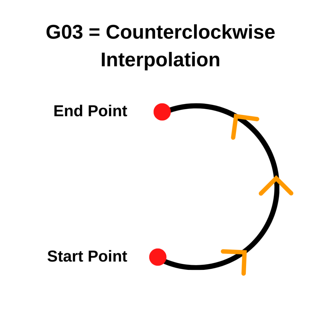
G03 tells your CNC machine to move in a counterclockwise circle. It follows a path along a set radius — like tracing the edge of a coin the other way — while cutting at a controlled speed.
Any time you need to cut a curved path going counterclockwise, G03 is the code you’ll use.
Key Takeaways
G03 moves the tool in a counterclockwise arc — use G02 for clockwise
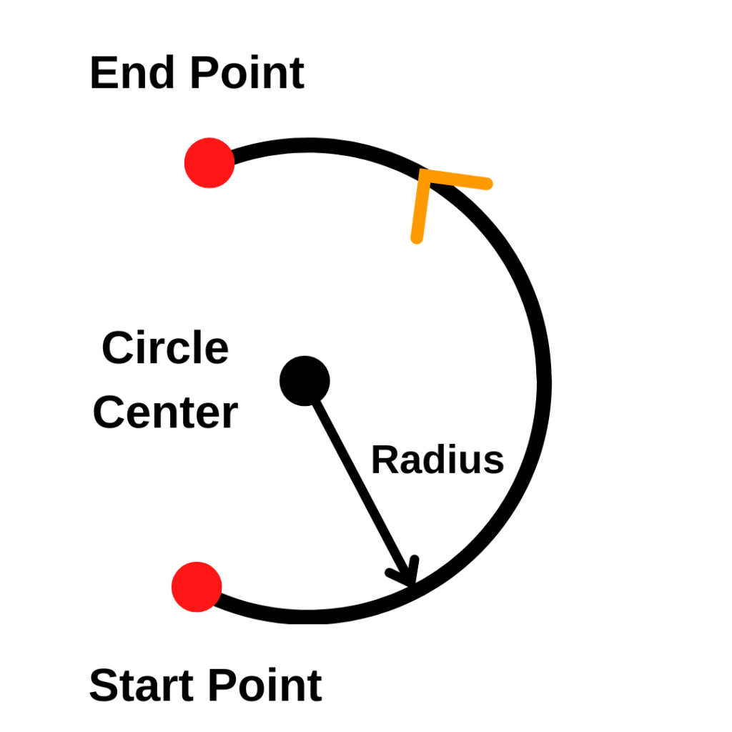
Requires an endpoint (X/Y) and a radius (R) or center offsets (I/J) to define the arc
It’s a modal code — it stays on until you switch to G00, G01, or G02
G03 and G3 are the same thing — the zero is optional
For full circles, use I/J instead of R
G03 – At A Glance
Function
Counterclockwise circular interpolation
Format
G03 X__ Y__ R__ F__ or G03 X__ Y__ I__ J__ F__
Type
Modal (Group 1 – Motion)
Cancelled by
G00, G01, G02
Required params
Endpoint (X/Y) + R or I/J
What Does G03 Do?
G03 moves the cutting tool along a counterclockwise arc from one point to another. You give it an endpoint and a radius, and it figures out the curved path between the two.
The machine doesn’t move in a perfect circle. It actually takes a series of very small straight steps that add up to look like a curve. This is called interpolation.
Zoomed in circular interpolation
To use G03, you need three things:
An endpoint — where the arc stops (X and Y coordinates)
A radius — how big the arc is (R), or center offsets (I and J)
G03 is a modal code. That means it stays active until you turn it off with another movement code like G00, G01, or G02.
G03 Format
The most common format uses the R word to set the radius:
G03 X__ Y__ R__ F__
You can also use I and J instead of R. I and J define the center of the arc as an offset from your starting point:
G03 X__ Y__ I__ J__ F__
Start with the R format — it’s easier to understand. Use I and J when you need to cut a full circle or an arc larger than 180°.
G03 Code Example
O0200                          (Program number)
G90 G54 G17 G21                (Absolute mode, work offset, XY plane, metric)
G00 X25. Y0.                   (Rapid to arc start point)
M03 S1200                      (Spindle on CW at 1200 RPM)
G43 H01 Z5.                    (Tool length comp, move to clearance height)
G01 Z-5. F100.                 (Feed down to depth)
G03 X0. Y25. R25. F200.        (Counterclockwise arc: 90° cut, 25mm radius)
G00 Z50.                       (Rapid to safe height)
M05                            (Spindle off)
M30                            (End program)
The tool starts at X25, Y0. It cuts a counterclockwise arc to X0, Y25 — a 90° curve with a 25mm radius. The radius in the R word matches the distance from the start point to the center of the arc.
COMMON MISTAKE – Using G03 When You Need G02
If the arc cuts in the wrong direction, stop the machine immediately.
G02 goes clockwise, G03 goes counterclockwise — viewed from above, looking down at the XY plane.
A quick check: if your arc should curve to the left, it’s G03. If it curves to the right, it’s G02. Always verify in simulation before you run it.
G03 vs G02
G02 and G03 work the same way. The only difference is direction. G03 goes counterclockwise. G02 goes clockwise. Both are viewed from above, looking down at the XY plane.
Which one you need depends on the shape of the part. Inside corners often use G03. Outside corners might use G02.
CAM software picks the right one for you automatically — but if you’re writing code by hand, think through the direction before you write it.
G3 vs G03 — Does the Zero Matter?
No. G3 and G03 do the exact same thing. The leading zero doesn’t change anything.
Textbooks and formal references tend to use G03 while many programmers will use G3 to save a keystroke. If your shop has a standard, follow it — otherwise use whichever you prefer.
When to Use G03
Use G03 any time you need to cut a counterclockwise arc or radius. Common situations:
Rounding an inside corner on a part
Cutting a full or partial circular profile
Blending a smooth radius between two straight cuts
Milling around a curved feature
In a real program, G03 usually comes after the tool is positioned, the length offset is applied (G43), and the tool has fed down to depth with G01.
A 25mm arc run in inches mode will move 25 inches — not what you want.
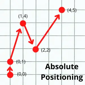
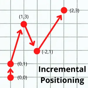
Absolute vs. Incremental Mode
How the controller interprets your coordinates depends on whether you’re in G90 (absolute) or G91 (incremental) mode.
Absolute (G90): coordinates are measured from the program zero.
Incremental (G91): coordinates are measured from the current position.
The images below show the difference between the absolute and incremental positioning modes. The numbers in parentheses are the locations given to the the machine to make the move.
Start and Stop Positions
Think through the full path the tool takes — not just the arc itself. Where is the tool starting? Where does it end up? Is there anything in between, like a clamp or vise jaw? It’s easy to forget about fixturing and end up crashing into it.
How to Cancel G03
There’s no specific cancel code for G03. Just switch to any other movement code:
G03 moves counterclockwise. G02 moves clockwise. Both use the same format — endpoint plus radius or I/J plus feed rate. The direction is the only difference.
Can I cut a full circle with G03?
Yes. Set your start and end point to the same location, then use I and J to define the center. You don’t need an X/Y endpoint when the arc starts and ends at the same spot.
When should I use I/J instead of R?
Use I/J for full circles and arcs over 180°. The R method can confuse some controls on large arcs. I/J is always explicit about where the center is.
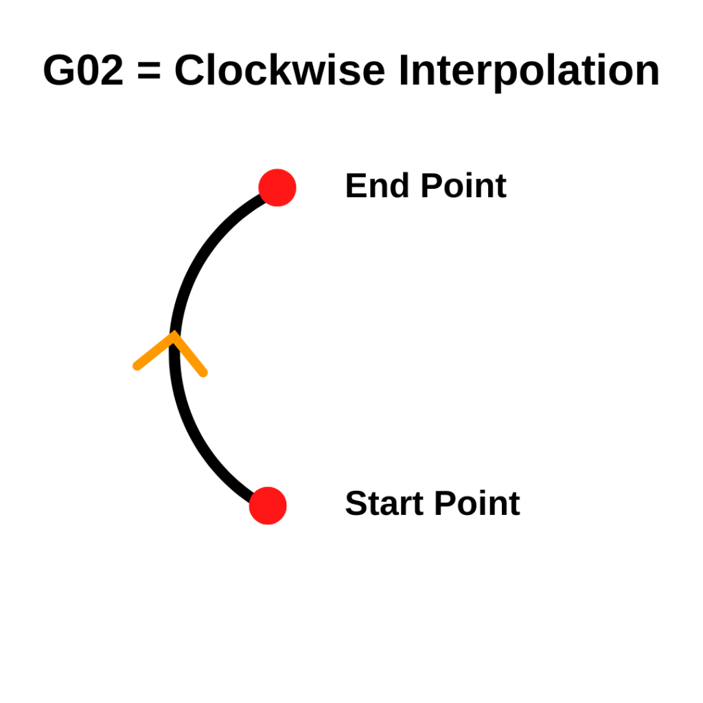
G02 tells your CNC machine to move in a clockwise circle. It follows a path along a set radius — like tracing the edge of a coin — while cutting at a controlled speed.
Any time you need to cut a curved path going clockwise, G02 is the code you’ll use.
Key Takeaways
G02 moves the tool in a clockwise arc — use G03 for counterclockwise
Requires an endpoint (X/Y) and a radius (R) or center offsets (I/J) to define the arc
It’s a modal code — it stays on until you switch to G00, G01, or G03
G02 and G2 are the same thing — the zero is optional
G02 – At A Glance
Function
Clockwise circular interpolation
Format
G02 X__ Y__ R__ F__ or G02 X__ Y__ I__ J__ F__
Type
Modal (Group 1 – Motion)
Cancelled by
G00, G01, G03
Required params
Endpoint (X/Y) + R or I/J
What Does G02 Do?
G02 moves the cutting tool along a clockwise arc from one point to another. You give it an endpoint and a radius, and it figures out the curved path between the two.
The machine doesn’t move in a perfect circle. It actually takes a series of very small straight steps that add up to look like a curve. This is called interpolation.
Zoomed in circular interpolation
To use G02, you need three things:
An endpoint — where the arc stops (X and Y coordinates)
A radius — how big the arc is (R), or center offsets (I and J)
G02 is a modal code. That means it stays active until you turn it off with another movement code like G00, G01, or G03.machine stays in clockwise arc mode until you switch to G00, G01, or G03.
G02 Format
The most common format uses the R word to set the radius:
G02 X__ Y__ R__ F__
You can also use I and J instead of R. I and J define the center of the arc as an offset from your starting point:
G02 X__ Y__ I__ J__ F__
Start with the R format — it’s easier to understand. Use I and J when you need to cut a full circle or an arc larger than 180°.
G02 Code Example
O0100 (Program number)
G90 G54 G17 G21 (Absolute mode, work offset, XY plane, metric)
G00 X0. Y-25. (Rapid to arc start point)
M03 S1200 (Spindle on CW at 1200 RPM)
G43 H01 Z5. (Tool length comp, move to clearance height)
G01 Z-5. F100. (Feed down to depth)
G02 X25. Y0. R25. F200. (Clockwise arc: 90° cut, 25mm radius)
G00 Z50. (Rapid to safe height)
M05 (Spindle off)
M30 (End program)
The tool starts at X0, Y-25. It cuts a clockwise arc to X25, Y0 — a 90° curve with a 25mm radius. The radius in the R word matches the distance from the start point to the center of the arc.
COMMON MISTAKE – Using a Negative R Value
A negative R value tells the machine to take the long way around the arc — more than 180°. A positive R takes the short route. Mix them up and the tool goes the wrong way, or cuts into your part.
Check your arc in simulation before you run it to make sure you got it right.
G02 vs G03
G02 and G03 work the same way. The only difference is direction. G02 goes clockwise. G03 goes counterclockwise. Both are viewed from above, looking down at the XY plane.
Which one you need depends on the shape of the part. Outside corners often use G02. Inside corners might use G03. CAM software picks the right one for you automatically — but if you’re writing code by hand, think through the direction before you write it.
G2 vs G02 — Does the Zero Matter?
No. G2 and G02 do the exact same thing. The leading zero doesn’t change anything.
Textbooks and formal references tend to use G02 while many programmers will use G2 to save a keystroke. If your shop has a standard, follow it — otherwise use whichever you prefer.
When to Use G02
Use G02 any time you need to cut a clockwise arc or radius. Common situations:
Rounding an outside corner on a part
Cutting a full or partial circular profile
Blending a smooth radius between two straight cuts
Milling around a curved feature
In a real program, G02 usually comes after the tool is positioned, the length offset is applied (G43), and the tool has fed down to depth with G01.
A 25mm arc run in inches mode will move 25 inches — not what you want.
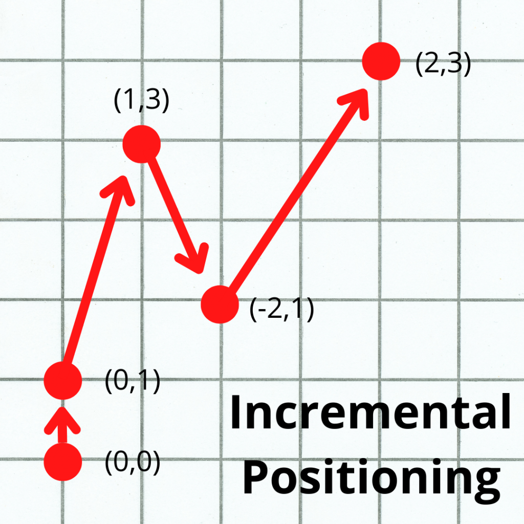
Absolute vs. Incremental Mode
How the controller interprets your coordinates depends on whether you’re in G90 (absolute) or G91 (incremental) mode.
Absolute (G90): coordinates are measured from the program zero.
Incremental (G91): coordinates are measured from the current position.
The images below show the difference between the absolute and incremental positioning modes. The numbers in parentheses are the locations given to the the machine to make the move.
Start and Stop Positions
Think through the full path the tool takes — not just the arc itself. Where is the tool starting? Where does it end up? Is there anything in between, like a clamp or vise jaw? It’s easy to forget about fixturing and end up crashing into it.
How to Cancel G02
There’s no specific cancel code for G02. Just switch to any other movement code:
G02 moves clockwise. G03 moves counterclockwise. Both use the same format — endpoint plus radius or I/J plus feed rate. The direction is the only difference.
Can I cut a full circle with G02?
Yes. Set your start and end point to the same location, then use I and J to define the center. You don’t need an X/Y endpoint when the arc starts and ends at the same spot.
When should I use I/J instead of R?
Use I/J for full circles and arcs over 180°. The R method can confuse some controls on large arcs. I/J is always explicit about where the center is.
G01 is the command that tells your CNC machine to move in a straight line while actively cutting material. If G00 gets the tool where it needs to be, G01 is what actually does the machining.
Key Takeaways
G01 moves the tool in a straight line at a feed rate you control with the F command
It’s modal — once called, it stays active until you switch to G00, G02, or G03
You must have a feed rate (F) set before or on the same line as G01, or the machine will alarm out
G01 is for cutting. G00 is for positioning. Don’t mix them up.
G1 and G01 are identical — the leading zero is optional
G01 – At A Glance
Function
Straight-line movement at a controlled feed rate
Format
G01 X__ Y__ Z__
Type
Modal (Group 1)
Cancelled by
G00, G02, G03
Requires
F (feed rate) — must be set
What Does G01 Do?
G01 sets the machine’s movement mode to linear interpolation — a straight-line move from the current position to a target XYZ location.
The CNC axes move so the path is perfectly straight, not a sequence of individual axis movements.
Speed is controlled by the F command (feed rate). You set a feed rate, call G01, give it a destination, and the machine handles the rest.
G01 is a modal command, which means it stays active until you replace it with another movement command — G00, G02, or G03. You don’t need to repeat G01 on every line.
Format for using a G01 code
The basic format is:
G01 X__ Y__ Z__ F__
You don’t need all three axes every time — include only the ones you’re moving. The F value only needs to appear once and stays in effect until you change it.
G01 X1.0 F20.0     (Move to X1.0 at 20 IPM — Y and Z don't move)
Y2.5               (Move to Y2.5 — still G01, still F20.0)
X3.0 Y4.0 Z-0.25   (Move all three axes simultaneously in a straight line)
G01 vs G1 — Is the Zero Required?
No. G01 and G1 are identical. Most CNC controls accept both.
In practice, experienced programmers often use the shorter G1 to save keystrokes. If your shop has a programming standard, follow it. If it’s your own code, use whichever format you prefer.
G01 vs G00
Both commands move the tool in a straight line. The difference is speed and intent.
G01 moves at your programmed feed rate. Use it when the tool is cutting material — the speed controls your chip load, surface finish, and tool life.
G00 moves at the machine’s maximum speed and ignores the feed rate entirely. Use it for positioning only — getting the tool to the right spot before you start cutting.
Real Program Example
O0101                           (Program number)
G90 G54                         (Absolute mode, work offset 1)
G00 X0.0 Y0.0                   (Rapid to start position)
G43 H01 Z0.5 M03 S1200          (Tool length comp, spindle on at 1200 RPM)
G01 Z-0.125 F10.0               (Feed to depth at 10 IPM — now cutting)
X4.0                            (Cut along X axis)
Y3.0                            (Cut along Y axis)
X0.0                            (Return along X)
Y0.0                            (Return along Y — square perimeter complete)
G00 Z1.0                        (Rapid clear)
M05                             (Spindle off)
M30                             (Program end)
G01 is called once and stays modal through the entire cutting section. The feed rate is set on that first line and carries through every cut that follows.
What to Watch Out For
Units — Inches vs Millimeters
Make sure your program has the right units code set. G20 is inches, G21 is millimeters. Moving 10 millimeters instead of 10 inches is a crash waiting to happen.
Absolute vs Incremental Mode
G01 works in whatever positioning mode is currently active. G90 (absolute) means all coordinates reference your work zero. G91 (incremental) means coordinates are relative to where you are right now. Know which one you’re in before writing moves.
The images below show the difference between the absolute and incremental positioning modes. The numbers in parentheses are the locations given to the the machine to make the move.
Know Your Path
G01 moves in a perfectly straight line from point A to point B. Before calling it, think about the path — not just the destination.
Clamps, vises, and fixture bolts live between start and end points. A move that looks correct on paper can still crash if something’s in the way.
COMMON MISTAKE – Forgetting Your Feed Rate
Calling G01 without a feed rate set on the same line or earlier in the program. On most controls this triggers an alarm. Always verify F is set before your first G01 cut.
How to Cancel G01
G01 doesn’t have a dedicated cancel command — you switch to another Group 1 movement code:
G00 moves at the machine’s maximum rapid speed and ignores the feed rate — use it for positioning only.
G01 moves at the feed rate you specify with the F command — use it whenever the tool is cutting material.
Does G01 need a feed rate on every line?
No. G01 is modal and so is the F command — both stay active once set. You only need to specify a new feed rate when you want to change cutting speed.
Can G01 move multiple axes at the same time?
Yes. If you include X, Y, and Z values on the same G01 line, the machine coordinates all three axes to move in a straight diagonal path to the target position.
Is G1 the same as G01?
Yes, they’re identical. The leading zero is optional and most modern CNC controls accept both formats.
G00 is the rapid traverse command in CNC G-code. It moves the machine at maximum speed — ignoring any programmed feed rate — along any combination of the X, Y, and Z axes.
It’s one of the first codes you’ll see in almost every CNC program.
Key Takeaways
G00 moves the machine at maximum speed — no cutting, no feed rate control
Use it to position the tool before a cut, after a tool change, or when moving to a safe height
Never use G00 while the cutter is in contact with the part
G00 is modal — it stays active until you switch to G01, G02, or G03
G0 and G00 are identical — the extra zero is optional
G00 – At A Glance
Function
Rapid Traverse (position at maximum speed)
Format
G00 X__ Y__ Z__
Type
Modal (Group 1 – Motion)
Cancelled by
G01, G02, G03
Feed rate
Ignored – machine runs at maximum rapid speed
WHAT DOES G00 DO?
G00 puts the machine into rapid traverse mode, sometimes referred to as rapid travel. When active, the CNC ignores any feed rate set with the F code and instead moves at the machine’s maximum speed. You can move any combination of the X, Y, and Z axes in a single G00 block.
G90 G54 (Absolute positioning, Work offset 1)
G00 Z1.0 (Rapid Z to safe height)
G00 X1.5 Y2.0 (Rapid to XY start position)
G43 H01 Z0.1 (Tool length comp, move to clearance plane)
G01 Z-0.5 F10.0 (Linear feed into the part — cutting begins)
G00 is only used while the cutter is clear of the part. G01 takes over the moment cutting starts, where feed rate control actually matters.
G0 VS G00 — IS THE EXTRA ZERO REQUIRED?
No. G0 and G00 are read identically by the CNC controller. The leading zero is a formatting preference, not a functional difference.
Textbooks and formal reference materials tend to use G00 while many programmers will use G0 to save a keystroke. If your shop has a standard, follow it — otherwise use whichever you prefer.
WHEN TO USE G00
G00 shows up constantly throughout a CNC program. Use it any time you need to move the tool quickly and there’s no cutting happening including:
Positioning to the start of a cut after a tool change
Pulling Z up to a safe clearance height between features
Moving to the tool change position (often combined with M05 and M09)
Repositioning to a new XY location between holes in a drilling pattern
COMMON MISTAKE – Cutting with G00
Never use G00 while the tool is in contact with the part.
Rapid traverse gives you no control over cutting conditions — the machine will move at full speed regardless of material, chip load, or tool diameter. The result is usually a broken tool, a scrapped part, or a machine crash.
Always switch to G01 (or G02/G03) before any cutting motion.
G00 FORMAT
Specify the destination coordinates for any axes you want to move:
G00 X__ Y__ Z__
You don’t need to include all three axes. These are all valid G00 commands:
G00 Z1.0  (move Z only)
G00 X3.0 Y4.5   (move X and Y simultaneously)
G00 X1.0 Y2.0 Z3.0  (move all three axes)
Because G00 is a modal code, you don’t need to repeat it on every line. If G00 is already active, the next line with coordinates will also execute as a rapid move.
IMPORTANT CONSIDERATIONS WHEN USING G00
Units — Inches or Millimeters
Make sure G20 (inches) or G21 (mm) is set before your G00 command. Moving 10 inches instead of 10 millimeters is a significant difference — and the machine won’t warn you.
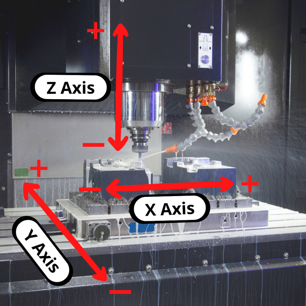
Absolute vs. Incremental Mode
How the controller interprets your coordinates depends on whether you’re in G90 (absolute) or G91 (incremental) mode.
Absolute (G90): coordinates are measured from the program zero. G00 X3.0 Y2.0 always moves to the same fixed location.
Incremental (G91): coordinates are measured from the current position. G00 X3.0 Y2.0 moves 3 inches in X and 2 inches in Y from wherever the tool is now.
The images below show the difference between the absolute and incremental positioning modes. The numbers in parentheses are the locations given to the the machine to make the move.
Most production programs run in G90. Check your setup block to confirm which mode is active before editing any G00 lines.
Know Your Path — Check for Obstacles
Before running a G00 move, think through the full path from start to finish. Where is the tool now, where is it going, and is there anything in between such as clamps, fixtures, the part, or the machine table itself.
G00 moves fast. There’s no time to react if something is in the way.
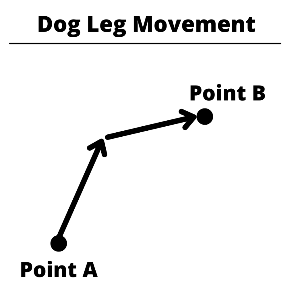
Machine Movement Behavior
Not all CNC machines behave the same way during rapid moves. Most will move all three axes simultaneously, which produces a straight-line path. Some machines move axes one at a time or at different speeds, producing a “dog-leg” path where the tool doesn’t travel in a straight line.
COMMON MISTAKE — Dog-Leg Movement: Don’t Assume a Straight Line
If your machine runs X, Y, and Z at different rapid speeds, a move that looks diagonal on paper can actually travel in a stepped path — potentially colliding with a clamp or part feature that a straight-line move would have cleared.
When in doubt, break the move into separate single-axis rapids or test at reduced rapid override before running full speed.
HOW TO CANCEL G00
There’s no dedicated cancel command for G00. To exit rapid traverse, switch to another motion code in Group 1 such as:
Using any of these codes will turn G00 rapid movement off and switch to the new movement mode.
G00 VS G01 — WHAT’S THE DIFFERENCE?
G01 also moves in a straight line, but at the feed rate set by the F code. G01 is the code used for cutting in a straight line. G00 is for rapid movement.
The rule is simple: if the tool is touching the part, use G01. If it’s not, G00 is faster.
OTHER RELEVANT CODES
The codes below are used with the G00 code or commonly found very close to a G00 command in the CNC program:
G00 moves the machine at maximum rapid speed with no feed rate control — it’s for positioning, not cutting. G01 moves in a straight line at the feed rate you specify with the F code. Use G01, G02, or G03 whenever the tool is in contact with the part.
Can I use G00 to cut material?
No. G00 ignores the feed rate and moves at the machine’s maximum speed. Using it while cutting gives you no control over chip load, surface finish, or tool load — and will almost certainly break the tool or damage the part.
Does G00 move in a straight line?
It depends on the machine. Most modern CNC machines move all axes simultaneously during a rapid, which produces a straight-line path.
However, there are still many older CNC machines in use and some machines move axes independently or at different speeds, creating a “dog-leg” path. Check your machine’s documentation or test at reduced rapid override if you’re unsure.
With the right engraving tool in your hands, you can finish creative tasks with ease.
And it’s a terrific way to personalize something generic with a fun crafty hobby.
Engraving tools come in a wide variety of styles, sizes, and capabilities. It’s important to find the ideal one at is ideal for your project.
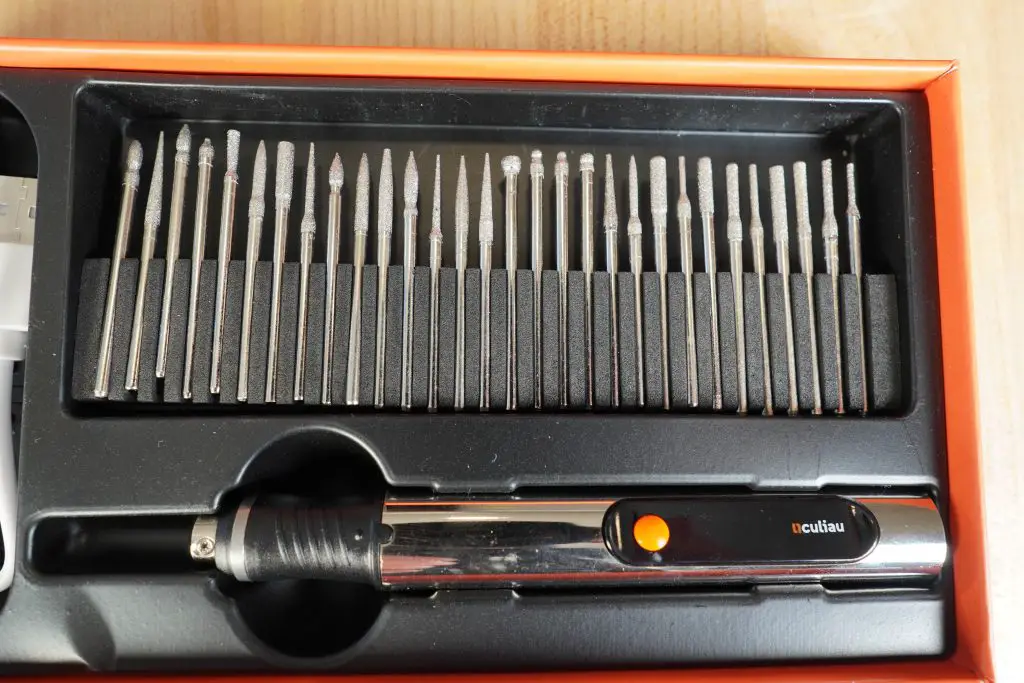
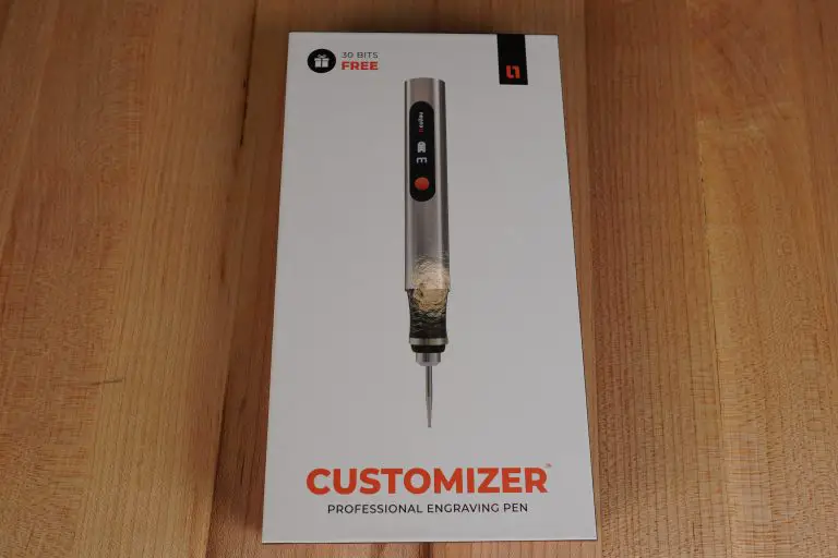
The Customizer by Resparked is an engraving pen that is more than capable of meeting most people’s needs. That’s why it’s a popular choice among home crafters and those who like to try out new tools for art.
The Customizer’s durability, power, compactness, and exceptional value for money make it an excellent professional etching tool suitable for all materials, including glass, wood, and metals.
Don’t get me wrong, it will still take practice to get a nice, finished product, but the Customizer is easier to use than some of the other bulkier engraving pens on the market.
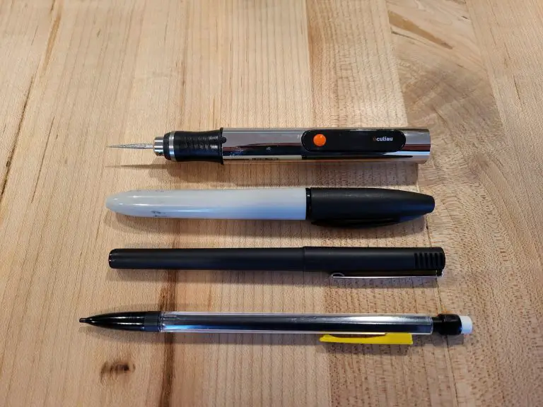
Size comparison of the Customizer
The Customizer is roughly the size of a regular marker. The textured grip and light weight make controlling the engraver while in use a snap.
You can sketch with it just like a normal pen or pencil.
The flexibility of this tool makes the job as simple as drawing on paper. It works well on wood, including hardwoods, glass, and metals such as steel, silver, and others.
The Customizer comes with a rechargeable battery and a USB charging wire. The run time is about 2 hours. And trust me 2 hours is more than enough time. Unless you are super experienced, your hand it going to get tired well before the 2 hours runs out.
Charging port and cable
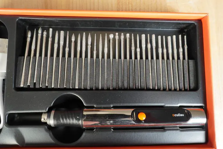
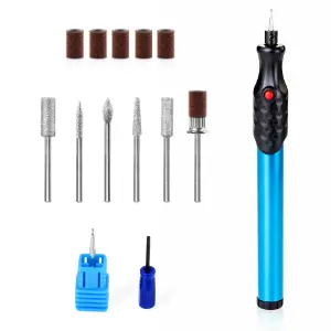
Also included is a large selection of engraving bits. They come in a variety of shapes and sizes which means you won’t need to pick up any extras for the Customizer right away.
Unless you plan to use it almost daily, there is a good chance you won’t need to get any more bits ever because the assortment that comes with the Customizer is well rounded.
The engraving bits that come with the Customizer
The engraving pen includes an LED display indicator, which shows you the battery level and speed of the tool.
One of the biggest indicators of the quality of the Customizer is the feel of the tool. This is a well built tool that feels good in the hand.
It is ergonomic, lightweight, and small. Because of this it is exceptionally comfortable to use and handle. The Customizer truly is a pocket-sized engraving machine.
The quality comes with a price though and the Customizer does cost more than some of the other engraving pens on the market. However, many of those cheaper engraving pens aren’t built as well. Often they just don’t feel good in your hand.
If you plan to use it a lot, I recommend going the Customizer from Resparked and avoiding all the generic copycats.
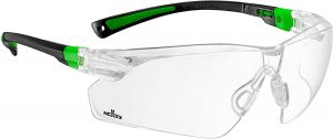
Above all, make sure you think safety first with any power tool. Proper eye protection. Consider gloves and a dust mask as well depending on the materials you plan to work with.
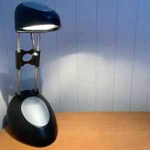
2. Use proper lighting
Nobody’s idea of a good time is engraving in the dark – and it’s not safe or productive.
Make sure your workplace has adequate light and that it is placed above or in front of you so that your head and shoulders don’t create a shadow on the work.
Proper lighting will make it much easier to see the fine details that you are creating on your workpiece.
3. Work on a clean surface
Before you begin, be certain that the surface you will be working on has been well cleaned.
Some materials can be cleaned with soap and water, others require special cleaning chemicals. Start with soap and water, it will work for most materials.
4. Use a template
Consider making a paper template to guide you. This helps in the beginning when you may lack the courage to do it all freehand.
Print out your design to trace or outline
It’s a good reference.
5. Practice
Just try.
If you want to learn it, then use it!
Practice different words and symbols on a piece of scrap material if you have it. Your first few designs will probably be rough. .
Another key point is to make sure you practice with the type of material you plan to work with. In other words, if you want to engrave on sea shells then find some to practice on.
Frequently asked questions
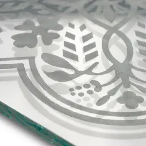
What kind of material can the Customizer work with?
An engraved piece of glass
The Resparked Customizer is capable of working with a wide range of materials including:
Wood
Plastic
Metal
Glass
Leather
Stone
Shells
Clay
Does the Customizer use standard Dremel style bits?
Unfortunately, the Customizer does not take Dremel bits straight out of the box. For an added cost, you can purchase an adaptor that will allow you to use them however.
How is customer support?
In my opinion good customer support says more about the product than just about any other feature.
Resparked has excellent customer support through email. [email protected] is their address and in my experience they are quick to answer any questions you might have, even if you just need tips for using your new tool.
Engraving pens come in a wide range shapes, sizes and capabilities. You want to find the one that is just right for you project.
As you read our guide to the best engraving pens, make sure to keep your planned project in mind to determine what tool will work best for you.
Some applications such as jewelry engraving will benefit from a smaller tool for more precise strokes. Other materials such as metal or glass will engrave better with a more powerful tool such as one of the engravers by Dremel below.
No matter what you are working with, we have laid out the best tools on the market and an extensive list of items at the bottom of the article for you to consider when looking for your right fit tool.
Easy to handle and use Customer service Plenty of included bits
Cons
Not the cheapest option
The Resparked Customizer Engraving Pen is excellent choice for novices. Because the tool is so light, engraving is as simple as using a pen.
Don’t get me wrong, it will still take practice to get a nice, finished product but the Customizer is easier to use than some of the other bulkier engraving pens on the market.
The Customizer is roughly the size of a regular marker. The grip and light weight make controlling the engraver while in use a snap.
Size comparison
You can sketch with it just like a normal pen or pencil.
One of the biggest indicators of the quality is the feel of the tool. This is a well-built tool that feels good in the hand.
The flexibility of the Customizer makes the job as simple as drawing on paper. It works well on wood, including hardwoods, glass, and metals like steel, silver, and others.
Plenty of included bits
It is ergonomic, lightweight, and small. Because of this it is exceptionally comfortable to use and handle. The Customizer truly is a pocket-sized engraving machine.
The quality comes with a price though and the Customizer does cost more than many of the other engraving pens on the market. The cheaper engraving pens aren’t built as well, but if you only plan to use it for the occasional project then it might not be a big deal.
If you plan to use it a lot, I recommend going with an engraving pen that is a step above such as the Customizer from Resparked and skipping all the generic cheapy ones.
The Easy Etcher is an excellent engraving pen for beginners. The tool is so lightweight that engraving with it is as close to using an actual pen as you will get. The Easy Etcher is actually about the size of a standard marker.
The rubberized grip also helps keep the engraver under control while using it. While the 12,000 RPM speed may seem under powered when compared to other engraving pens, it actually helps keep the tool stable during use.
Runtimes will vary depending on the type of material you are working with, but the Easy Etcher runs on AAA batteries which means there is no waiting around for the tool to recharge. The batteries aren’t included but other extras are.
The Easy Etcher comes with 10 sets of stencils that make engraving text or designs on your material a piece of cake. It also comes with a nice starter selection of bits that allow you to create a variety of textures and finishes.
The Easy Etcher won’t be the be all, end all for engraving every material but it is a great tool to get you started without breaking the bank.
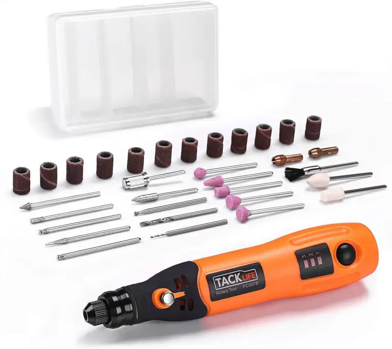
While the TACKLIFE PCG018 is not as nimble as the Easy Etcher it does a good job of making up for it in the power department. With similar price points, it would be wise to determine whether power or maneuverability is more important to you.
The PCG018 has 3 speed settings of 5, 10 and 15,000 RPMs. This means it will work well for a variety of materials.
This TACKLIFE engraving pen is cordless and rechargeable. It charges over USB which has some benefits and drawbacks.
The charge time is fairly long at 2 hours but with a runtime of 90 minutes it lasts long enough to complete most jobs.
Additionally, the tool comes with 31 different accessories for engraving, sanding and finishing along with a case to contain them all. Two collets to accommodate different bit sizes of 3/32” and 1/8” is also a nice addition.
The TACKLIFE PCG018 is a solid choice when it comes to cordless engraving pens.
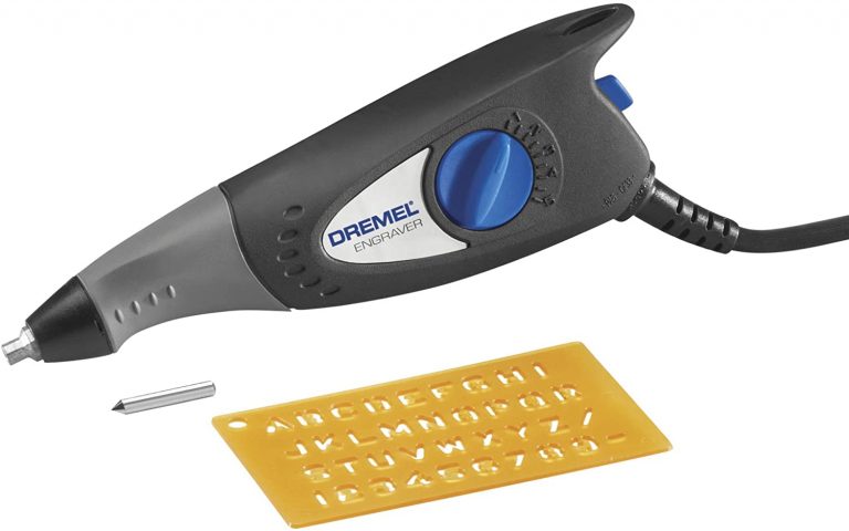
The Dremel 290-01 is different than most of the other engravers on this list. Instead of being a rotary engraver, it has a vibrating tip that moves in and out. Basically, it operates like a mini jackhammer.
Corded engraving pens like this Dremel have some advantages and disadvantages.
Being corded means that you are tethered to your power outlet and it can be slightly cumbersome to work with the power cord snagging on objects in your work area. The 290-01 is pretty lightweight though which makes maneuvering it around your workpiece a little easier.
A nice benefit of using a corded engraver is that you won’t ever run out of power. This is helpful for harder materials that may take multiple passes to get the amount of engraving you desire.
The power of the 290-01 is controlled with a dial that allows five depth settings. This works well to adjust for different material types such as wood or rock. All that power comes with the side effect that the tool is quite loud when running. You should expect it to be noisy. It is a power tool after all but take note that the other tools on this list are quieter.
There are a couple minor downfalls for the 290-01. The biggest one is that the bit can be difficult to install. The set screw that locks it is tiny and it can be challenging to work with.
Also, the provided stencil comes in handy but is somewhat lacking. Many other engravers come with a wider variety of stencils so keep in mind that you may want to purchase some extra stencils if you plan on engraving a lot.
On the plus side, just like this engraving pen’s cordless counterpart, the Dremel 290-01 comes with a two-year warranty which is well above what most competing engravers come with.
Overall, the Dremel 290-01 is a solid engraving pen. A couple minor inconveniences are balanced nicely by the higher, non-stop power that comes from being always plugged in.
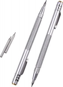
If all you need is something basic and reliable for engraving then the manual scriber from IMT may be your best bet.
It requires no batteries or power cord. The tool is extremely lightweight and its tungsten carbide tip will engrave a large variety of materials including steel, ceramics and glass. If you are working with plastics though, a powered tool would be a better choice.
The IMT scriber will actually perform an operation that is more akin to scratching your material than actually engraving it. For many use cases, this is more than enough. Just keep this in mind when choosing your engraving pen.
It also comes with extra tips in case one snaps. They are somewhat brittle because they are so hard. They aren’t fragile but can break if you aren’t dropped or handled roughly. Luckily, the scriber comes with a protective cap that will help shield the point from damage.
The IMT scriber is definitely more low tech than some of the other engraving pen options available but if all you need is a simple engraver then it may be a great choice at a cheap price.
Remember that these tools can be dangerous, especially to your eyes. Be careful handling them and use eye protection to protect you from things such as flying chips or broken bits.
Corded vs cordless engraving pens
Corded engraving pens generally have more power than their cordless counterparts. The downside is that the cord can get in the way and make the tool more difficult to maneuver. The easiest engraving pens to use are those that are lightweight and battery operated.
Cord length
If you choose to use a corded engraving pen to have more power, keep in mind that the length of the power cord is very important. If the cord is short, then make sure that you have an extension cord handy because some of the power cords can be very short.
Speed
RPMs do not equal power. Being able to adjust your RPMs over a wider range is more beneficial than simply having a higher RPM overall. Different materials will require different RPMs. In general, materials such as glass or metal which are harder will benefit from a higher RPM and softer materials will engrave better at lower RPMs.
Bits and accessories
It is a nice bonus for an engraving pen to come with a good selection of bits and accessories but not a necessity. There are many bit or accessory kits available that allow you to perform different types of engravings or finishing to your piece for a fairly cheap price.
Extra bits aren’t required to start but before too long you will definitely want to expand your bit collection if your engraving pen doesn’t come with many. Different bits will allow you to different styles of engraving.
Battery
If you go the cordless route, make sure you find a tool that charges quick and has a long runtime.
Cheaper tools tend to run off standard AA or AAA batteries which means they can run out of power quickly but also that more power can easily be on standby. Keep extra batteries nearby but consider the amount of power you will need for your project when choosing which engraving pen to go with. Harder materials require more power.
Warranty
Pay attention to the length of the warranty for your tool. Just like many other power tools, a good warranty is a solid indicator of the quality of the tool. This doesn’t mean that good tools don’t come with shorter warranties, just that it is something to be mindful of.
Stencils
Stencils can be very important for getting the correct design on your part. There are many different stencil kits available but it is definitely a bonus to have a couple to start with. Creating visually appealing designs freehand is going to take some practice so having a template to follow when getting started will be helpful.
Engraving vs cutting
Engraving pens are just that, engravers. They generally are not meant for cutting. If you are looking for a tool that is capable of doing more than simply scratching the surface of a part, then you will want to look into something with more power like the various Dremels or other higher power rotary tools.
Related articles
For more information check out these related articles:
To provide the best experiences, we use technologies like cookies to store and/or access device information. Consenting to these technologies will allow us to process data such as browsing behavior or unique IDs on this site. Not consenting or withdrawing consent, may adversely affect certain features and functions.
Functional
Always active
The technical storage or access is strictly necessary for the legitimate purpose of enabling the use of a specific service explicitly requested by the subscriber or user, or for the sole purpose of carrying out the transmission of a communication over an electronic communications network.
Preferences
The technical storage or access is necessary for the legitimate purpose of storing preferences that are not requested by the subscriber or user.
Statistics
The technical storage or access that is used exclusively for statistical purposes.The technical storage or access that is used exclusively for anonymous statistical purposes. Without a subpoena, voluntary compliance on the part of your Internet Service Provider, or additional records from a third party, information stored or retrieved for this purpose alone cannot usually be used to identify you.
Marketing
The technical storage or access is required to create user profiles to send advertising, or to track the user on a website or across several websites for similar marketing purposes.