G90 G-Code: Absolute Positioning Mode Explained

G90 sets your CNC machine to absolute positioning mode. Every move you program will be measured from a fixed zero point — usually your work offset (like G54) or machine home.

Key Takeaways

  • G90 activates absolute positioning mode — all moves are measured from a fixed zero point
  • It’s modal, meaning it stays active until you switch to G91 (incremental mode)
  • Most CNC programs run in G90 for the majority of their code
  • G90 is commonly included in the safety block at the start of each tool section
  • Forgetting to set G90 when your machine is in G91 can cause the tool to move to the wrong location
G90 – At A Glance
FunctionAbsolute positioning mode
TypeModal (Group 3)
Cancelled byG91
Common useSafety block, program startup
Paired withG54–G59 (work offsets), G00, G01

What does G90 do?

When G90 is active, every coordinate you program tells the machine exactly where to go — measured from the same zero point every time.

If you tell the machine to go to X2.0, it moves to the location that is 2.0 inches from your part zero. It doesn’t matter where the tool currently is. The machine always goes to that exact spot on the coordinate grid.

This is different from G91 (incremental mode), where each move is measured from wherever the tool is right now.

graph paper example of absolute positioning with multiple points as examples
graph paper example of incremental positioning with multiple points as examples

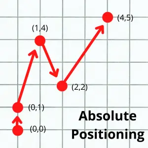
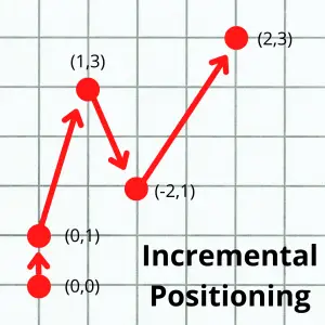
The diagrams above show this difference clearly. In absolute mode, all your coordinates point back to one origin. In incremental mode, each move uses the last position as the new starting point.

G90 vs G91: Which mode does what?

Most CNC programs are written mostly in G90. Here’s why: it’s easier to think in absolute coordinates when you’re working from a part print.

Your print says the hole is at X1.500, Y2.000 from the datum. You just type that directly into your program. You don’t have to calculate how far from your last move that is.

G91 (incremental) gets used for specific situations — like when you want to drill a row of evenly spaced holes without calculating every absolute position.

Both G90 and G91 are modal commands. Once you turn one on, it stays on until you switch to the other. There’s no “off” code — G90 and G91 cancel each other.

COMMON MISTAKE – Leaving the machine in G91 when you start a new section of code

Why it matters: If the previous operation used G91 and you forget to call G90, all your absolute coordinates will be interpreted as incremental moves. The tool will go to the wrong position — and if there’s a fixture or clamp in the way, you could crash the machine.

The calculator below shows both modes side by side. Enter the positions you want to hit, and it will show you what those coordinates look like written in G90 (absolute) versus G91 (incremental) — and generate the actual G-code for each.

G90 vs G91 — See the Difference
# Enter position (X, Y) G90 — Absolute G91 — Incremental
Always from part zero
From previous position

Now that you can see the difference, here is how G90 looks in a real program:

G90 code example

Here’s a simple example of G90 used in a program to drill three holes:

G90 G54 G00 X1.0 Y1.0       (Absolute mode, work offset, rapid to first hole)
G43 H01 Z1.0 M03 S1000       (Tool length comp on, spindle on)
G99 G81 Z-0.5 R0.1 F8.0      (Drill cycle, first hole)
X2.5 Y1.0                    (Second hole — X2.5, Y1.0 from part zero)
X4.0 Y1.0                    (Third hole — X4.0, Y1.0 from part zero)
G80                           (Cancel canned cycle)
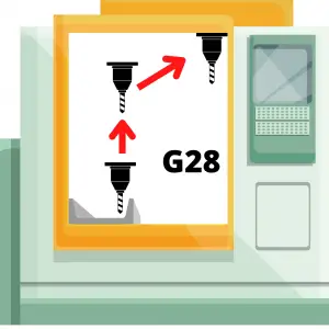
G91 G28 Z0.0                  (Incremental move to machine home — Z only)
G90                           (Back to absolute mode)
M30                           (End of program)

Notice how all the hole positions (X1.0, X2.5, X4.0) are measured from the same part zero — that’s G90 at work. The brief switch to G91 at the end is used for the machine home move, then G90 is called again before the program ends

When to use G90

You’ll see G90 in nearly every CNC program — typically right at the top in the safety block (also called a safety line).

A safety block is a line of code run at the start of each new section to make sure the machine is in the correct modes. It usually looks something like this:

G90 G40 G49 G80

This single line sets the machine to absolute positioning (G90), cancels cutter compensation (G40), cancels tool length compensation (G49), and cancels any active canned cycle (G80) — all at once.

Running this before each tool change helps prevent crashes from leftover modal states.

FAQs

What does G90 mean in CNC?

G90 is the G-code that activates absolute positioning mode. When G90 is active, all coordinate values in your program are measured from a fixed zero point — usually the workpiece zero set by your work offset (G54–G59).

What is the difference between G90 and G91?

G90 uses absolute positioning — every move is measured from a single fixed zero point. G91 uses incremental positioning — every move is measured from wherever the tool currently is. Both are modal, and they cancel each other.

Does G90 need to be programmed at the start of every CNC program?

It’s best practice to include G90 in your safety block at the start of each tool section. Even if the machine defaults to G90 at power-up, explicitly calling it ensures your program won’t behave unexpectedly if a previous operation left the machine in G91.

Can you mix G90 and G91 in the same program?

Yes. Switching between absolute and incremental mode in the same program is common. A typical example is using G90 for all machining moves and briefly switching to G91 for a machine home (G28) move at the end of a tool section, then returning to G90.

G81 G-Code: Standard Drilling Canned Cycle Explained

G81 is the standard drilling canned cycle in CNC machining. It drills straight down to your programmed Z depth and retracts in one smooth motion — no pecking, no dwell. It’s the go-to code for shallow holes that don’t need chip-clearing breaks.

Key Takeaways

  • G81 performs a simple, one-pass drilling operation with no pecking or dwell
  • It’s a modal code — it stays active until you cancel it with G80
  • Use G81 for shallow holes; switch to G83 for deep holes that need chip clearing
  • The Z value in G81 sets the bottom of the hole, not the start of the cut
  • Always pair G81 with G98 or G99 to control where the tool retracts after each hole
G81 – At A Glance
FunctionStandard drilling canned cycle
FormatG98/G99 G81 X_ Y_ R_ Z_ F_
TypeModal (Group 9)
Cancelled byG80
Used withG98, G99, X, Y, Z, R, F

What Does G81 Do?

When you call G81, the machine moves to your X/Y position, plunges the spindle to the Z depth you specified, and then retracts. That’s the whole cycle. No stopping at the bottom, no stepping back out in increments.

It’s a modal function, which means once you activate it, it stays active. Every X/Y position you call after G81 will trigger another drill cycle at that same Z depth and feed rate — until you cancel it.

When to Use G81

G81 is the right choice when your hole is shallow enough to drill in one shot. A good rule of thumb: if your hole depth is less than 3x the drill diameter, G81 will usually work without chip buildup.

Common uses include:

  • Through holes in thin stock
  • Spot drilling to start a hole location
  • Center drilling
  • Counterboring (with the right tool)
  • Reaming and boring shallow holes

If your hole is deeper — say 5x the drill diameter or more — chip packing becomes a real problem. In that case, use G83 (peck drilling with full retract) or G73 (peck drilling with partial retract) instead.

G81 code format

The standard format for G81 is:

G98 G81 X_ Y_ R_ Z_ F_

Here’s what each word means:

  • G98 or G99 — sets the retract plane (covered below)
  • G81 — activates the drilling canned cycle
  • XY — hole location in the XY plane
  • R — the R plane, the Z position the tool rapids to before feeding into the hole
  • Z — the bottom of the drilling motion (not the top of the hole)
  • F — feed rate for the drilling pass

Important: In most real programs, the X and Y coordinates are on a separate line before the G81 call. You’ll commonly see it written like this:

X2.0 Y3.0
G98 G81 R0.1 Z-0.75 F12.0

The machine moves to X2.0 Y3.0 first, then the G81 line fires the cycle.

COMMON MISTAKE – Confusing the Z value with the top of the hole

Why it matters: Z in G81 is the bottom of the drilling motion, not where the drill touches the part. If your part surface is at Z0.0 and you want a 0.75″ deep hole, Z should be Z-0.75 — not Z0.75.

Getting this backwards means either a crash or a hole that doesn’t go deep enough.

Working G81 Example

Here’s a short program that drills three holes in a row:

G90 G54 G00 X1.0 Y1.0        (Rapid to first hole position)
G43 H01 Z1.0                  (Tool length comp, Z to initial point)
G98 G81 R0.1 Z-0.75 F12.0    (Drill first hole, retract to Z1.0)
X2.0                          (Second hole — G81 stays active)
X3.0                          (Third hole)
G80                           (Cancel canned cycle)
G00 Z1.0                      (Retract to safe Z)

In this example, G81 stays modal through all three hole locations. The R plane (R0.1) gives the drill a 0.1″ clearance above the part surface before it begins feeding. G98 sends the tool back to Z1.0 (the initial point) after each hole.

COMMON MISTAKE – Forgetting to cancel G81 with G80

Why it matters: G81 is modal. If you don’t cancel it, every X/Y move after it will trigger another drill cycle — including any positioning moves you intended to be rapids. This can drill holes in places you didn’t plan, or worse, plunge into a fixture.

Retract Planes: G98 vs G99

Every G81 call needs either G98 or G99 to tell the machine where to go after each drill cycle.

G98 sends the tool back to the Z position the machine was at when G81 was first called — the initial point. This is the safer option. Use it when there are fixtures, clamps, or raised features between your holes.

G99 sends the tool back to the R plane after each hole. Since the R plane is close to the part surface, this is faster. Use G99 only when you know the path between holes is clear.

visualization of how a cnc machine moves using g98 and g99 codes shows motion of travel for the machine

Setting your R plane too low is a common crash source — especially when moving between widely spaced holes. Setting it too high wastes cycle time. A value of 0.1″ above the part surface is a safe starting point for most setups.

COMMON MISTAKE – Using G99 when obstacles exist between holes

Why it matters: G99 retracts only to the R plane, which is just above the workpiece. If there’s a clamp, step, or raised boss between two hole locations, the tool can slam right into it at rapid speed.

Try it yourself to see what can happen

G81 Three-Hole Drill — G98 vs G99 Retract

Program — active line highlighted
( Tool 1 — 0.5" drill )
X1.000 Y0.000( position: hole 1 )
G98G81R0.100Z-0.750F12.0
X2.500 Y0.000( hole 2 — clamp nearby )
X4.000 Y0.000( hole 3 )
G80( cancel canned cycle )
Z–0.750"
R0.100"
0.300" above surface
Normal
Cycle Log
  • G98 is active. The drill returns to the initial point between every hole — well above the clamp.
  • Switch to G99 and run to see the crash.
ModeG98
Hole
Drill Z0.000"
StatusIdle

Absolute vs. Incremental Positioning

G81 reads X, Y, Z, and R values based on whatever positioning mode is active — G90 (absolute) or G91 (incremental).

G90 (absolute): All coordinates are measured from the work zero point. This is the standard for most programs.

G91 (incremental): Coordinates are measured from the tool’s current position. This mode is less common but useful for bolt circle patterns or evenly spaced hole patterns.

Double-check your active positioning mode before running a G81 cycle. The wrong mode won’t trigger an alarm — it’ll just drill in the wrong place.

How to Cancel G81

Use G80 to cancel G81 and all other canned cycles. Once G80 is active, the machine returns to normal operation and won’t drill on subsequent XY moves.

You can also cancel G81 by calling a different canned cycle code, which automatically replaces the current one. But using G80 explicitly is cleaner and easier to read.

G81 vs similar Drilling cycles

CodeNameBest Used For
G81Standard drillingShallow holes, one-pass operations
G82Spot drillingDrilling with a dwell at the bottom
G83Peck drilling (full retract)Deep holes, full chip clearance
G73Peck drilling (partial retract)Moderate depth, faster cycle time
G74Left-hand tappingLeft-hand threaded holes
G85Left-hand threaded holesPrecision bore holes, feed in/out

FAQS

What does G81 do in CNC?

G81 activates the standard drilling canned cycle. It moves the spindle to your programmed X/Y position, feeds down to the Z depth, and retracts — in one pass with no dwell or pecking.

What is the difference between G81 and G83?

G81 drills in one continuous pass, while G83 uses a peck drilling pattern — the drill feeds down a set distance, retracts fully to clear chips, then feeds deeper again. Use G81 for shallow holes and G83 for deep holes where chips could pack and break the drill.

How do you cancel a G81 canned cycle?

Use G80 to cancel G81. Without G80, the cycle stays active and the machine will attempt to drill a hole at every XY position called after the G81 line.

What is the R value in G81?

The R value sets the R plane — the Z height the tool rapids to before feeding into the part. It should be just above your part surface, typically 0.1″ in most setups. The R plane also acts as the retract height when G99 is active.

G73 G-Code: High-Speed Peck Drilling Cycle Explained

G73 is a CNC canned cycle for high-speed peck drilling. Instead of plunging in one shot, it drills in small steps — pecking down and retracting slightly between each one. This breaks up chips and keeps the drill from packing up.

Key Takeaways

  • G73 drills in incremental steps (pecks) with a short retract between each one
  • The short retract breaks chips but doesn’t fully clear the hole — that’s what G83 is for
  • Q sets the depth of each peck; the cycle repeats until it reaches the Z depth
  • Cancel G73 with G80 or the machine will keep drilling at every XY position in the program
  • Use G73 when hole depth is 3–4× the drill diameter or more
G73 – At A Glance
FunctionHigh-Speed Peck Drilling Cycle
TypeModal / Canned Cycle
Cancelled byG80
Required parametersX, Y, Z, R, Q, F
Optional parametersK or L (repetitions)

What Does G73 Do?

G73 is a modal command that puts the machine into a peck drilling cycle. Each time you give it an XY position, it drills to the Z depth in steps — dropping by the Q amount, retracting slightly, then drilling again until it reaches full depth.

The retract after each peck is just a small amount — enough to break the chip but not enough to pull the drill completely out of the hole. That’s the key difference between G73 and G83.

Difference between peck drilling and standard drilling

illustration that shows the difference between peck drilling and standard drilling in a CNC machine

Standard drilling is a straight shot — the drill goes in and comes back out. One move. It works great for shallow through-holes in softer materials.

Peck drilling breaks that into multiple smaller cuts. The drill advances to a set depth (Q), retracts slightly, then advances again. This accomplishes two things: it breaks long stringy chips into shorter pieces, and it keeps chips from packing up in the flutes and causing tool breakage.

Peck Drilling Visualizer — G73 vs G83

Live G-Code — adjust sliders to see it change
G73 X1.000 Y1.000 R0.100 Z-1.500 Q0.250 F8.0 ( 6 pecks )
Z–1.500"
Q0.250"
R0.100"
F8.0
Normal
Cycle Log
  • Adjust sliders, then press Run Cycle.
ModeG73
Current Z0.000"
Pecks Done0
Pecks Needed6
Total Depth1.500"

The general rule: if the hole depth is 3 to 4 times greater than the drill diameter, use a peck cycle. Below that ratio, a standard G81 cycle usually handles it fine.

G73 Syntax and Parameters

The basic format for G73 looks like this:

G73 X__ Y__ R__ Z__ Q__ F__ L__

Here's what each parameter does:

  • X — Hole position in the X axis
  • Y — Hole position in the Y axis
  • R — The R plane (clearance height). The tool rapids to this Z level before starting each new hole
  • Z — Final depth of the hole (where the drill stops)
  • Q — Peck depth. How far down the drill advances on each peck. This is an incremental value
  • F — Feedrate in inches per minute (or mm/min). Depends on your material and drill diameter
  • K or L — Number of times to repeat the cycle at the same position (machine dependent — check your control manual)

COMMON MISTAKE - Leaving Q out of the G73 block

Why it matters: On most controls, omitting Q causes an alarm or the machine drills to full depth in a single pass — defeating the whole point of the peck cycle. Always specify Q.

G73 Program Example

Here's a realistic G73 program:

G90 G54 G00 X1.0 Y1.0         (Rapid to first hole)
G43 H01 Z1.0 M03 S1200        (Tool length comp, spindle on)
G73 X1.0 Y1.0 R0.1 Z-1.5 Q0.25 F8.0  (Peck drill — 0.25" pecks to 1.5" depth)
X2.5 Y1.0                     (Second hole — G73 still active)
X4.0 Y1.0                     (Third hole)
G80                            (Cancel canned cycle)
G91 G28 Z0                    (Return Z to home)
M05                            (Spindle off)

In this example, the drill will take six pecks of 0.25" to reach the 1.5" depth, with a short retract between each one.

COMMON MISTAKE - Not canceling G73 with G80 before moving to a new operation

Why it matters: G73 is modal. If you forget G80, the control will try to peck drill at the next XY coordinate you program — even if that move was intended for something else entirely.

How to cancel a G73 code?

Use G80 to cancel G73 and all other canned cycles. Once G80 is active, XY moves return to normal rapids or linear moves.

You can also cancel a canned cycle by calling a different canned cycle code — but G80 is the clean, explicit way to do it.

G73 on a Lathe vs. a Mill

G73 means something completely different on a CNC lathe. On a lathe, G73 is a pattern repeating cycle — the machine cuts the same profile multiple times, stepping in toward the finished dimension on each pass. It's used for turning rough stock down to shape.

If you're programming a lathe and see G73, don't confuse it with peck drilling. Always check whether you're working on a mill or a lathe.

When to Use G73

G73 is a good choice when:

  • Hole depth is 3–4× the diameter or more — deeper holes accumulate chips fast
  • You're drilling in a material that makes long, stringy chips — aluminum and some steels are notorious for this
  • Cycle time matters — because G73 only retracts slightly, it's faster than G83

G73 is not the right choice when:

  • You need to fully clear chips from the hole (use G83 instead)
  • You're drilling very deep holes where chip buildup is severe

G73 vs. G83: Which One Should You Use?

Both G73 and G83 are peck drilling cycles. The difference is how far the tool retracts after each peck.

G73 retracts just enough to break the chip — the tool stays inside the hole. G83 retracts all the way out to the R plane — fully clearing chips from the hole on every peck.

an illustration that shows the difference between the G73 and G83 CNC codes
G73G83
Retract per peckShort (chip break only)Full retract to R plane
Best forModerate depth, stringy chipsDeep holes, heavy chip load
Cycle timeFasterSlower
Chip clearancePartialComplete

Use G73 when the material makes manageable chips and you want speed. Use G83 when you're drilling deep and need to fully evacuate chips between pecks.

G73 vs Drilling Cycles

CodeNameWhen to Use
G81Standard DrillingSimple through-holes, no peck needed
G82Spot DrillingDrilling with a dwell at the bottom
G83Deep Hole Peck DrillingDeep holes, full chip clearance required
G73High-Speed Peck DrillingModerate depth, faster cycle time

FAQs

What is G73 used for in CNC machining?

G73 is a canned cycle for high-speed peck drilling. It drills a hole in multiple steps, retracting slightly after each peck to break chips. It's used when hole depth is 3–4 times the drill diameter or greater.

What is the difference between G73 and G83?

Both are peck drilling cycles, but G73 only retracts a short distance after each peck to break the chip. G83 retracts all the way to the R plane, fully clearing chips from the hole. G83 is better for deeper holes with heavier chip loads; G73 is faster.

How do you cancel a G73 canned cycle?

Use G80 to cancel G73 and all other canned cycles. If G73 is not canceled with G80, the machine will continue peck drilling at every XY position that follows in the program.

What does Q do in a G73 cycle?

Q sets the peck depth — how far the drill advances on each individual pass before retracting. For example, Q0.25 means the drill pecks 0.25 inches at a time until it reaches the programmed Z depth.

G28 G-Code: Machine Zero Return Explained for Beginners

G28 tells your CNC machine to move to a safe intermediate point, then rapid all the way to the machine’s home position. It’s one of the most common safety commands in CNC programming — and one of the easiest to crash a machine with if you use it wrong.

Key Takeaways

  • G28 moves the machine to an intermediate point first, then returns to the machine zero position
  • Always pair it with G91 (incremental mode) to avoid crashing into your workpiece
  • Use it before tool changes, pallet changes, or any time you need the machine out of the way
  • It is NOT a modal command — it only runs once on the line it appears
  • G28 Z only (Z-axis first) is the safest approach in most programs
G25 – At A Glance
FunctionMachine Zero Return (Reference Point Return)
FormatG28 [axis][value]
TypeNon-modal (one-shot)
Typical UseBefore tool changes, end of program, safe retract
Related CodesG53, G28.1, G29, G30

What Does G28 Do?

G28 moves the machine in two steps. First, it rapids to an intermediate point you specify. Then it rapids from that point to the machine’s zero position (also called the home position or reference point).

That intermediate stop is the key. Without it, a direct rapid to machine zero could slam the tool straight through a clamp, a vise jaw, or the part itself.

illustration of a cnc machine that shows how the machine moves when using a g28 code
The tool moves to intermediate point, then to machine zero

Think of it like backing a car out of a tight parking spot. You don’t just floor it in reverse — you pull out at an angle first to clear the car next to you, then straighten out.

When to use a G28 code?

G28 shows up near the end of a tool path section, right before the machine needs to do something else — like a tool change or a pallet change.

Common situations where you’ll use it:

  • Before an M06 tool change
  • At the end of a program (returning the machine to home)
  • Before a pallet change on a horizontal machining center
  • Any time you need to guarantee the machine is clear of the part and fixtures
a cnc mill with multiple fixtures and coolant lines
G28 helps you avoid fixtures like these

G28 and the G91 Pairing — Why It Matters

This is where most beginners get tripped up.

G28 uses whatever positioning mode is currently active — absolute (G90) or incremental (G91). If your program is in absolute mode (which most programs are), the intermediate point values in G28 are interpreted as work coordinates. That means the machine might try to move to X0 Y0 Z0 of your workpiece before going to machine zero — and that’s a crash.

COMMON MISTAKE – Running G28 X0 Y0 Z0 while still in absolute mode (G90)

Why it matters: In absolute mode, X0 Y0 Z0 refers to your work offset zero — which is likely right on top of your part. The machine will try to move there before going to machine zero. This is one of the most common crash scenarios in CNC programming.

The fix is simple: add G91 on the same line as G28.

G91 G28 Z0       (Switch to incremental, move 0 units in Z, then return Z to machine zero)
G90              (Switch back to absolute mode)

With G91 active, the intermediate point values are treated as distances from the current position. A value of Z0 means “move zero units in Z first, then go to machine zero” — so the tool goes straight home without an intermediate detour.

COMMON MISTAKE – Forgetting to restore G90 after using G91 with G28

Why it matters: If absolute mode isn’t restored before the next tool’s program begins, every position in your program will be interpreted as an incremental move. This can cause rapid crashes on the very first move of the next operation.

Always put G90 on the line immediately after your G28 block.

Z First — The Safest Approach

In most programs, you’ll see G28 used on the Z-axis alone before touching X or Y.

G91 G28 Z0       (Retract Z to machine zero first)
G90
G91 G28 X0 Y0    (Then home X and Y — optional, often not needed)
G90

Moving Z first clears the tool out of the part before moving the table. If you home X and Y with the spindle still down in the cut, you’re dragging the tool across the part — or worse.

G28 Code Examples

G28 G91 Z0 — Most Common Usage

G91 G28 Z0       (Incremental mode, Z moves 0 units, then rapids to machine zero)
G90              (Restore absolute mode)

This is the line you’ll see in the vast majority of CNC programs before a tool change. The Z-axis returns to its home position. X and Y are unaffected.

G28 X0 Y0 Z0 — All Axes Home

G91 G28 X0 Y0 Z0    (All three axes move to machine zero simultaneously)
G90

Use this at the end of a program when you want the machine fully homed. Be aware that all three axes move at the same time — so make sure your tool is already clear of the part before running this.

G28 G91 Z35.0 — Clearance Move First

G91 G28 Z35.0    (Move Z up 35mm from current position, then home Z)
G90

When you need guaranteed clearance before homing — for example, if you’re in a deep pocket — specify the clearance distance instead of zero. The tool moves up 35mm first, then rapids to machine zero.

G28 U0 W0 — CNC Lathe Syntax

G28 U0 W0        (Return to machine zero on a CNC lathe)

On many CNC lathes, U and W are the incremental axis designators for X and Z respectively. Using U0 W0 with G28 returns both axes to machine zero with no intermediate move — a common and safe pattern on lathes.

cnc lathe cutting threads on part

G28 vs G53 — What’s the Difference?

G53 is G28’s close cousin. Both can move the machine to a safe position using machine coordinates.

The key difference: G53 lets you specify exactly where you want to go in machine coordinates, on a single line. G28 always goes all the way to machine zero.

G53 is often more flexible — you can use it to position the spindle at a tool changer or a pallet station without sending everything to machine zero. But not every CNC control supports G53. G28 works on virtually every machine.

Pick one and stick with it consistently. Mixing G28 and G53 in the same shop makes programs harder to read and troubleshoot.

G28 vs G28.1

G28.1 lets you define where G28 goes. When you run G28.1 at a specific position, that position becomes the new reference point for future G28 commands — instead of the default machine zero.

Most shops never need G28.1. It’s useful in specific setups where machine zero isn’t a practical home position. If you’re just getting started, ignore it for now and use G28 the standard way.

Is G28 a modal command?

No. G28 is a one-shot (non-modal) command. It executes once on the line where it appears, and that’s it.

Compare that to something like G90 or G91, which stay active until you change them. G28 doesn’t “stay on” — it runs its two-step move and then the machine does whatever comes next.

FAQs

What is G28 used for in CNC programming?

G28 returns the machine to its home (zero) position. It’s most often used before tool changes and at the end of programs to move the machine clear of the workpiece and any fixtures.

Why do you use G91 with G28?

G91 switches the machine to incremental positioning mode. This makes the intermediate point in G28 a relative move from the current position, not an absolute coordinate. Without G91, if your program is in absolute mode, G28 could try to move to work coordinate zero — which might be right on top of your part.

What’s the difference between G28 and G53?

Both codes can move the machine using machine coordinates. G28 always moves to machine zero (in two steps). G53 lets you specify any machine coordinate position on a single line, making it more flexible. G53 is not supported on all controls; G28 is universal.

Does G28 move all axes at once?

Only the axes you specify. G28 Z0 only moves the Z-axis. G28 X0 Y0 Z0 moves all three. When multiple axes are specified, they all move simultaneously in each step.

G04 Dwell Code: What It Does and How to Use It

G04 tells your CNC machine to pause in place for a set amount of time. The tool stops moving, but the spindle and coolant keep running. Once the time is up, the machine reads the next line of code and picks up where it left off.

Key Takeaways

  • G04 is the dwell command — it pauses machine motion for a specified amount of time
  • The spindle and coolant stay on during a dwell; only the axis motion stops
  • Dwell time is set with a letter (P, F, U, or X) that varies by machine and controller
  • G04 resumes automatically — unlike M00 or M01, no button press is required
  • Always check your machine manual: some controllers use seconds, others use milliseconds
G04 – At A Glance
FunctionDwell (timed pause)
FormatG04 P___ or G04 F___ (letter varies by controller)
TypeNon-modal (one-shot — active only for the block it’s programmed on)
Spindle during dwellStays on
Coolant during dwellStays on
ResumesAutomatically after dwell time expires

What Does G04 Do?

G04 is the dwell command. It tells the machine to sit still for a specified amount of time before moving on to the next line in the program.

Think of it as a pause button — but one the machine releases on its own. You set the time, the machine waits, then it moves on without any input from you.

When Should You Use G04?

There are three main reasons machinists reach for G04.

Breaking chips on a lathe

When you’re turning long, stringy materials like stainless steel or aluminum, the chip can grow into one continuous ribbon that wraps around the part or the tool.

Those chips are sharp!

A short dwell breaks the chip so it falls free. It’s a simple fix that saves a lot of cleanup — and prevents those razor-sharp stringers from becoming a safety hazard.

Improving surface finish

Dwelling at the bottom of a hole or at the end of a facing pass gives the tool time to clean up the surface before retracting. On milling operations, it can smooth out the bottom of a pocket. On turning, it can improve finish on a shoulder or face.

Giving the machine time to catch up

CNC machines are fast, but not every function happens instantly. Coolant takes a moment to flow. A pallet changer needs time to complete. If you’re programming a move right after one of these events, a G04 can give the machine the margin it needs before the next operation begins.

G04 Syntax and Format

Here’s where G04 gets a little inconsistent. The dwell time format varies by machine brand and controller. Three things can change depending on what you’re running:

1. The letter used to call out the time

Common options are P, F, U, and X. Fanuc controls typically use P. Check your machine manual to confirm which letter your controller expects.

2. Seconds vs. milliseconds

Some controllers treat the number as seconds. Others treat it as milliseconds. This matters a lot — a dwell of P3 could mean 3 seconds or 3 milliseconds depending on the machine.

1 second = 1000 milliseconds

3. Decimal or no decimal

Some controllers require a decimal point. Some don’t allow one. And some accept either but interpret the number differently based on whether you include the decimal.

Here’s an example of how the same 3-second dwell might look on three different controllers:

G04 P3       (3 seconds on some controls — e.g., Fanuc with integer = seconds)
G04 P3000    (3 seconds on controls that use milliseconds with no decimal)
G04 U3.0     (3 seconds on some lathe controls — decimal = seconds)

COMMON MISTAKE – Assuming your controller uses seconds when it actually uses milliseconds (or vice versa)

Why it matters: G04 P3 on a milliseconds-based controller gives you a 3-millisecond dwell — essentially nothing. G04 P3000 on a seconds-based controller pauses the machine for 50 minutes. Always confirm the format in your machine manual before running a new dwell in a program.

The bottom line: Always verify how your specific machine handles G04 before using it in a real program. Consult the machine manual or contact the manufacturer if you’re not sure.

G04 Program Example

Here’s how G04 looks in a real drilling program. In this case, we’re dwelling at the bottom of each hole to improve the finish on the hole floor.

G90 G54 G00 X1.0 Y1.0       (Rapid to first hole position)
G43 H01 Z0.1 M03 S1500       (Tool length comp on, spindle on)
G01 Z-0.5 F5.0               (Feed to bottom of hole)
G04 P1.0                     (Dwell 1 second at bottom — improves finish)
G00 Z0.1                     (Retract)
X2.5 Y1.0                    (Move to second hole)
G01 Z-0.5 F5.0               (Feed to bottom)
G04 P1.0                     (Dwell again)
G00 Z0.1                     (Retract)
M05                          (Spindle off)
M30                          (Program end)

The G04 P1.0 line tells the machine to wait 1 second at the bottom of the hole before retracting. The spindle keeps spinning the whole time — only the Z-axis stops moving.

G04 vs G4: Is the Zero Required?

No. G04 and G4 are identical. The CNC controller reads them the same way.

You’ll typically see G04 written with the leading zero in textbooks and reference materials. In practice, many programmers drop the zero and just write G4. Either format is fine.

If you work in a shop with a style standard, follow whatever format the team uses. If you’re on your own, pick one and be consistent.

How G04 Differs from M00 and M01

G04, M00, and M01 all pause the machine — but they work very differently.

With G04:

  • The machine pauses for the programmed time, then resumes on its own
  • The spindle stays on
  • Coolant stays on
  • No operator input required

With M00 (program stop):

  • The machine stops completely — spindle off, coolant off
  • The program won’t resume until the operator hits cycle start
  • Useful when you need to measure a part mid-cycle or swap a clamp
fanuc cnc control panel with cycle start button highlighted
Cycle start on a Fanuc control

With M01 (optional stop):

  • Same as M00, but only activates if the optional stop switch is turned on at the control
  • Useful for stopping during setup and skipping the stop in production

Use G04 when you just need a timed pause and want the machine to keep running. Use M00 or M01 when you need a human to intervene before continuing.

Canned Cycles with Built-In Dwell

If you’re drilling or boring, you may not need a standalone G04 at all. Several canned cycles have dwell built right into the code:

These are worth knowing about. If you’re already using a canned cycle, the built-in dwell is often the cleaner solution.

FAQs

What is G04 used for in CNC programming?

G04 is the dwell command. It pauses machine motion for a set amount of time while keeping the spindle and coolant running. Common uses include breaking chips on a lathe, improving surface finish at the bottom of a hole, and giving machine functions like coolant or pallet changers time to complete.

Does G04 turn off the spindle?

No. During a G04 dwell, the spindle keeps running. Only the axis motion stops. If you need to stop the spindle, use M05.

What is the difference between G04 and M00?

G04 pauses for a timed amount of time and resumes automatically. M00 is a full program stop — it turns off the spindle and coolant and waits for the operator to press cycle start before continuing.

Why does my G04 not seem to be dwelling long enough?

Your controller may be interpreting the dwell value as milliseconds instead of seconds. G04 P1 on a milliseconds-based controller dwells for only 1 millisecond — effectively nothing. Check your machine manual to confirm whether your controller uses seconds or milliseconds, and adjust your value accordingly.

F Code in CNC Programming: How Feedrate Works (With Examples)

The F code sets the feedrate — how fast the cutting tool moves through the material. It’s one of the most important values in any CNC program. Set it too slow and you waste time. Set it too high and you break tools.

Key Takeaways

  • F sets the cutting speed (feedrate) for moves made with G01, G02, G03, and most canned cycles
  • G00 (rapid) ignores the F value entirely — the machine always rapids at max speed
  • Two feedrate modes exist: per minute (in/min or mm/min) and per revolution (in/rev or mm/rev)
  • Mills typically run in per-minute mode (G94); lathes more often use per-revolution mode (G99)
  • Feedrate stays active until you change it — it’s a modal command
F Code – At A Glance
FunctionSets the cutting feedrate
FormatF[value] — example: F15.0 or F0.008
TypeModal (stays active until changed)
Used withG01, G02, G03, canned cycles
Ignored byG00 (rapid travel)
Unit modes (mill)G94 = per minute, G95 = per revolution
Unit modes (lathe)G98 = per minute, G99 = per revolution

What Does the F Code Do?

The F code tells the machine how fast to move the cutting tool when making a cut. It works with any motion code that cuts material — linear moves (G01), arcs (G02/G03), and drilling cycles.

One thing to know right away: G00 ignores the feedrate. Rapid moves always run at the machine’s maximum speed, no matter what F value was last programmed.

F Code Format

The basic format is just the letter F followed by a number:

F15.0

Decimal points are allowed. The number of decimal places depends on the unit mode your machine is running.

  • Inch, per minute: one decimal place — example: F12.5
  • Metric, per minute: one decimal place — example: F200.0
  • Inch, per revolution: four decimal places — example: F0.0846
  • Metric, per revolution: three decimal places — example: F0.329

Feedrate Modes: Per Minute vs. Per Revolution

Per Minute (mm/min or in/min)

This mode sets how far the tool travels in one minute. It does not depend on spindle speed — if the spindle slows down, the feed rate stays the same.

This mode is standard on most mills. It’s activated with G94 on mills and G98 on lathes.

Per Revolution (mm/rev or in/rev)

This mode sets how far the tool moves per spindle rotation. As the spindle speeds up or slows down, the feed automatically adjusts to keep chip load consistent.

This mode is common on lathes. It’s activated with G95 on mills and G99 on lathes.

Most lathes switch between these modes regularly depending on the operation. Most mills stay in per-minute mode.

COMMON MISTAKE – Forgetting that G98 and G99 mean something different on lathes vs. mills

On a mill, G98 is a canned cycle return mode (initial point). On a lathe, G98 sets feedrate per minute. Copying code between machine types without checking this will cause problems.

F Code in a Real Program

Here’s what F looks like in context on a mill program:

G90 G54 G00 X1.0 Y0.5      (Rapid to start position)
G43 H01 Z0.1               (Tool length offset, move to clearance)
G01 Z-0.25 F5.0            (Feed down to depth at 5 in/min)
G01 X3.0 F15.0             (Feed across at 15 in/min)
G00 Z1.0                   (Rapid back to clearance — F ignored)

What Factors Affect the Right Feedrate?

There’s no single correct feedrate — it depends on your specific setup. Here are the main factors:

Cutting Tool

  • Sharpness: A dull tool requires slower feeds to avoid breaking
  • Size: Larger tools can generally handle higher feeds than small diameter tools
  • Material: Carbide tools run faster than high-speed steel (HSS). Ceramic tools can run faster still

Workpiece Material

Softer materials like aluminum, brass, and plastic allow much higher feedrates than tough materials like stainless steel or titanium. Start conservative with any new material.

Spindle Speed

Feedrate and spindle speed work together. “Speeds and feeds” are paired for a reason — they both affect chip load, heat, and tool life.

Depth and Width of Cut

illustration showing the depth of cut on a cnc machine

Deeper or wider cuts put more force on the tool. When you increase depth or width, you typically need to slow the feed down to compensate.

Coolant

cnc machine table with coolant lines and spindle shown
Flood coolant in use

Flood coolant reduces heat and can allow higher feedrates. Running dry often means cutting slower.

Machine Condition

a white and black cnc machine
Not everyone works with a machine this nice

Worn or loose machines may need slower feeds to hold tolerance and avoid vibration. A newer, rigid machine handles higher feeds better.

How to Calculate Feedrate

Milling Feedrate (per minute)

The standard formula for milling feed rate is:

Feed Rate (in/min) = RPM × Number of Flutes × Chip Load
  • RPM = spindle speed in revolutions per minute
  • Number of flutes = number of cutting edges on the tool
  • Chip load = how thick each chip should be (get this from your tool manufacturer’s chart)

Example: 4-flute end mill, RPM = 2000, chip load = 0.004 in/tooth

Feed Rate = 2000 × 4 × 0.004 = 32.0 in/min

Program that as: F32.0

Converting Between Per Minute and Per Revolution

Feed per revolution = Feed per minute ÷ RPM
Feed per minute = Feed per revolution × RPM

Example: F200.0 mm/min at 1000 RPM = 200 ÷ 1000 = 0.200 mm/rev

COMMON MISTAKE – Too aggressive chip load for a long tool

A long tool deflects more than a short one. The same chip load that works fine on a short end mill can cause chatter, poor finish, or breakage on a long reach tool.

When sticking out more than 3× the tool diameter, reduce your feed rate.

How to Choose a Starting Feedrate

Most machinists start with manufacturer specs — the tool data sheet or catalog will give you recommended chip loads and speeds for different materials. Use those as your starting point, then adjust from there.

Good starting resources:

  • Tool manufacturer charts (Kennametal, Sandvik, OSG, etc.)
  • Machinery’s Handbook
  • CAM software (most calculate feeds and speeds automatically)
  • Online feeds and speeds calculators (FSWizard, G-Wizard, etc.)

General guidelines:

  • Carbide tools can run faster than HSS — in some cases 3–5× faster
  • Harder workpiece materials need slower feeds
  • Slower feeds = longer tool life, less heat, better finish
  • Most manufacturers give a range — start at the low end and work up

Feedrate Override

feedrate override knob on a Lillian VMC 1100 CNC mill
Feedrate override knob on a Lillian VMC 1100 CNC mill

The feedrate override knob on the machine control panel lets the operator adjust the programmed feedrate on the fly — anywhere from 0% to 200% of the programmed value.

This is useful when running a new program for the first time. Set the override to 50% and gradually increase it as you gain confidence in the program.

COMMON MISTAKE – Forgetting about your feedrate override

Why it matters: The next operator (or you, later) assumes the machine is running at programmed speed.

Cycle times will be off, and the parts may not be cut correctly if feeds are intentionally matched to spindle speeds.

FAQs

What does the F code control in CNC?

The F code controls the feedrate — the speed at which the cutting tool moves through the material during a cut. It applies to G01 linear moves, G02/G03 arc moves, and most canned cycle operations.

Does G00 use the F code?

No. G00 (rapid positioning) always moves at the machine’s maximum speed regardless of the F value. The feedrate is only active during cutting moves.

What’s the difference between feed per minute and feed per revolution?

Feed per minute sets how far the tool moves in 60 seconds, independent of spindle speed. Feed per revolution sets how far the tool moves per spindle rotation, so it automatically adjusts if the spindle speed changes. Lathes commonly use per-revolution mode (G99); mills typically use per-minute mode (G94).

How do I know what feedrate to use?

Start with the tool manufacturer’s recommended chip load for your material. Multiply chip load × number of flutes × RPM to get your starting feed per minute. Adjust based on machine rigidity, tool stickout, and cut depth.

D Code in CNC: What It Does and How to Use It (Diameter Offset)

The D code tells your CNC machine how wide the cutting tool is. That measurement gets stored in the controller and used when cutter compensation is active. Without it, the machine has no idea where the edge of the tool actually is.

illustration of a cnc cutting tool that shows what an D offset is

Key Takeaways

  • The D code selects which diameter offset register the machine uses during cutter compensation
  • D offsets are stored in the tool offset table — you type the tool’s diameter (or radius, depending on your control) directly into that register
  • Cutter compensation must be turned on with G41 or G42 for the D offset to have any effect
  • The D number usually matches the tool number — D1 for Tool 1, D2 for Tool 2, and so on
  • Only one D offset can be active at a time
D Code – At A Glance
FunctionSelects the diameter offset register for cutter compensation
Used WithG41 (cutter comp left), G42 (cutter comp right)
Value StoredTool diameter or radius (depends on control)
Cancelled byG40 (cutter compensation cancel)

What does the D code do?

The D code picks which offset register your machine reads when cutter compensation is active. Think of offset registers like numbered slots in a spreadsheet — each one holds a value for a specific tool. D1 points to slot 1, D2 to slot 2, and so on.

When you turn on cutter compensation with G41 or G42, the machine reads the value stored in that D register and shifts the tool path by that amount. Without a D value, the machine doesn’t know how far to shift.

What is cutter compensation?

Cutter compensation is a mode that lets the CNC adjust the tool’s path based on the tool’s size. Instead of programming around the exact centerline of the cutter, you can program the part profile and let the machine do the math.

an animation showing how the cnc machine will move with cutter compensation left on

When compensation is active, the machine shifts the tool path by half the diameter — which is the radius. G41 shifts the tool to the left of the programmed path. G42 shifts it to the right. The direction is based on looking in the direction of travel.

an animation showing how the cnc machine will move with cutter compensation right on

The practical benefit: you can program one set of coordinates and change how the part comes out just by adjusting the D offset value. That flexibility is what makes cutter compensation useful in a real shop.

How to use the D code in a program

The D code appears on the same line as G41 or G42. Here’s what a basic cutter compensation block looks like:

G90 G54 G00 X0 Y0          (Rapid to start position)
G41 D01 G01 X1.0 F15.0     (Turn on cutter comp left, use D1 offset)
Y3.0                        (Move along profile)
X4.0                        (Continue)
Y0                          (Continue)
G40 G00 X0 Y0              (Cancel cutter compensation, return to start)

In this example, D01 tells the machine to read offset register 1. Whatever diameter value is stored there, the machine uses it to shift the tool path to the left of the programmed profile.

COMMON MISTAKE – Leaving cutter compensation active

Leaving cutter compensation active (G41/G42) at the end of a program or before a tool change.

Why it matters: Most controls require G40 to cancel cutter compensation before a tool change or program end. Skipping G40 often triggers an alarm, and on some machines it can cause unexpected moves.

an animation showing how a cnc machine will move when cutter compensation is off

Where are D offset values stored?

D offset values live in the tool offset table — a table built into the machine’s control. You can usually find it by navigating to the offset or tool page on the control panel.

Offset Library
Tool offset table with D offsets listed on the right side

The table lists every offset register available on the machine. You type the tool’s diameter directly into the matching register. For a 0.5″ end mill assigned to Tool 1, you’d enter 0.5 into the D1 register.

Some controls store the radius instead of the diameter — meaning you’d enter 0.25 for that same tool. Check your machine’s manual if you’re not sure. Entering the wrong value (diameter when it expects radius, or vice versa) is one of the most common setup mistakes.

COMMON MISTAKE – Entering the radius instead of the diameter (or vice versa) in the D offset register

Why it matters: The machine will cut at the wrong size. A 0.500″ end mill entered as 0.500 radius will shift the path 0.500″ instead of 0.250″ — doubling the offset. This usually means the part comes out undersized or the cutter crashes.

D offset numbering

The D number doesn’t have to match the tool number, but it’s strongly recommended. Keeping them the same (D1 for T01, D5 for T05) makes programs easier to read and troubleshoot.

Here’s what a tool call with a D offset looks like in context:

T01 M06               (Call Tool 1, execute tool change)
G43 H01 Z1.0 F-      (Apply tool length offset H1)
G41 D01 G01 X0.5 F12.0  (Apply cutter comp left with D1 offset)

You can have multiple D offsets stored in the machine at once — one for each tool. But only one can be active at a time. Calling a new D number while compensation is active cancels the previous one.

mach 3 tool offset table
Tool offset table

D offset vs. H offset

D and H offsets both live in the tool offset table, but they control different things.

D offset — stores the diameter (or radius) of the tool. Used with G41 and G42 to control side-to-side position of the cutter.

H offset — stores the length of the tool. Used with G43 to control how far down the Z-axis the tool reaches.

illustration of a cnc cutting tool that shows what an D offset is
illustration of a cnc cutting tool that shows what an H offset is

Most programs use both. A full tool compensation setup in the header of a program typically looks like this:

T02 M06               (Tool change to Tool 2)
G43 H02 Z1.0          (Tool length comp using H2)
G41 D02 G01 X0 F10.0  (Cutter comp left using D2)

H02 handles the Z-axis. D02 handles the XY plane. Together they give the machine the full picture of the tool’s size.

For more on H offsets and tool length compensation, see the G43 page.

FAQs

What does D mean in CNC code?

What does D mean in CNC code?

Do you need a D offset if you’re not using cutter compensation?

No. The D offset only does something when G41 or G42 is active. If you’re not using cutter compensation, the D code has no effect on the tool path.

Can you have more than one D offset active at a time?

No. Only one D offset can be active at a time. You can store as many as your machine supports, but only the currently called D number is in use.

What happens if I forget to program a D offset with G41?

Most controls will default to D0 if no D offset is specified, which means a stored value of zero — no offset shift. Your tool will cut right on the programmed line. On some controls, omitting the D code can also trigger an alarm or undefined behavior, depending on the machine.

G-Code Comments: How to Add Them (By Machine Brand)

G-code comments are notes inside your CNC program that the controller ignores. They help operators, setup people, and your future self understand what the program is doing — without changing how the machine runs.

Key Takeaways

  • Comments are ignored by the CNC controller — they’re notes for humans, not the machine
  • The two most common comment characters are parentheses () and the semicolon ;
  • Fanuc, Haas, Hurco, Mitsubishi, and Yasnac use parentheses; Heidenhain and Siemens use a semicolon
  • Place comments at the start of program sections and after key moves — not on every line
  • Avoid placing comments in the middle of a line if you want maximum machine compatibility

How G-Code Comments Work

A comment is a section of your program that the controller reads but skips over. It doesn’t move any axes, change the spindle speed, or trigger any machine action. Its only job is to communicate information to whoever is reading the code.

Different machine brands use different characters to mark a comment. Knowing which one your machine uses is important — use the wrong character and some controllers will throw an alarm.

Comment Characters by Manufacturer

Machine Control ManufacturerG-Code Comment Character
FanucParentheses ()
HaasParentheses ()
HeidenhainSemicolon ;
HurcoParentheses ()
MitsubishiParentheses ()
Sinumerik (Siemens)Semicolon ;
YasnacParentheses ()

When in doubt, check your machine’s programming manual. There are dozens of control manufacturers out there, and some older or less common controls use different conventions.

How Parentheses Work

When you use parentheses, the controller ignores everything between the opening and closing parenthesis:

G00 X1.0 Y1.0 (RAPID TO FIRST HOLE POSITION)
G43 H01 Z1.0  (TOOL LENGTH COMP - 1/2 INCH DRILL)

Only the text inside the () is treated as a comment. The rest of the line runs normally.

COMMON MISTAKE – Putting a semicolon inside parentheses on a Fanuc/Haas machine.

Why it matters: On these controls, the semicolon inside the parens is just part of the comment text — it won’t comment out the rest of the line. Only what’s inside the parentheses is ignored.

How the Semicolon Works

On Heidenhain and Siemens controls, a semicolon tells the controller to ignore everything after it on that same line:

G00 X1.0 Y1.0 ; RAPID TO FIRST HOLE POSITION
G43 H01 Z1.0  ; TOOL LENGTH COMP - 1/2 INCH DRILL

Everything to the right of the ; on that line is ignored. A semicolon on a Fanuc machine behaves differently — it marks the end of a block, not a comment.

COMMON MISTAKE – Using a semicolon as a comment on a Fanuc control.

On Fanuc, the semicolon is an end-of-block character (like a carriage return). Using it as a comment delimiter can confuse the controller or cause errors depending on the version.

What to Include in a G-Code Comment

Keep comments short and useful. A comment that fills three lines of text is harder to read than no comment at all.

Good things to include:

  • Tool number and description (T01 = 1/2″ DRILL)
  • Operation being performed (ROUGH FACE, FINISH BORE, DRILL HOLES)
  • Offset numbers being used (H01, D01)
  • Instructions for the operator (INSPECT PART BEFORE CONTINUING, FLIP PART HERE)
  • Program revision or date at the top of the file

Here’s a realistic example of a well-commented program header:

%
O1001 (PART: 12345-A HOUSING - REV 2)
(DATE: 2024-09-01  PROGRAMMER: B. FOWLER)
(MATERIAL: 6061 ALUMINUM)
(MACHINE: HAAS VF-2)
(-----TOOL LIST-----)
(T01 - 3/4 INCH FLAT ENDMILL)
(T02 - 1/2 INCH DRILL)
(T03 - 1/2-13 TAP)

This kind of header is worth the extra lines. Anyone who opens the program — including you, six months from now — can understand it at a glance.

Where to Put Comments in Your CNC Program

There are a few spots where comments consistently add value.

At the top of the program — Include a header block with the part name, revision, programmer name, date, machine, and tool list. CAM software often generates this automatically.

At the start of each section — When you switch from one operation to another (roughing to finishing, drilling to tapping), a comment line helps the operator track where they are:

(-----BEGIN DRILLING CYCLE-----)
G99 G83 Z-1.25 Q0.25 R0.1 F12.0

At the end of key lines — A brief note after a critical move or setting is enough:

G92 S3000 (SPINDLE SPEED LIMIT)
G50 S3000 (MAX RPM - LATHE)

Avoid Putting Comments in the Middle of a Line

Some Fanuc-based controls allow inline parentheses comments mid-line, but not all do. Stick to end-of-line comments for the best cross-machine compatibility.

When to Use Comments (And When to Skip Them)

Use comments where they genuinely help someone understand the program. You don’t need to comment every single line.

A good rule: comment at transitions and at the top of each tool or operation. That’s usually enough. If someone reads your header and your section comments, they should be able to follow the program without needing a note on every G00.

On older machines or machines with limited memory, excessive comments can increase program size. It’s rarely a problem today, but worth keeping in mind if you’re running a very old control.

FAQs

Do g-code comments slow down the machine?

No. The controller reads and ignores them — they don’t affect machine motion, feed rate, or cycle time in any meaningful way.

Can I put a comment anywhere in the program?

Generally, yes — but the safest approach is at the end of a line or on its own line. Putting comments in the middle of active code can cause errors on some controllers.

What happens if I use the wrong comment character for my machine?

On many controls, using the wrong character will just be ignored or cause a syntax error. On some machines, an unrecognized character in the wrong place can stop the program or trigger an alarm. Always verify the correct character for your specific control.

Do all CNC machines support comments?

Most modern CNC controls do. Very old or simplified controls may not support them, or may only support one format. When in doubt, check the programming manual for your specific machine.

G85 G-Code: The Ream/Bore Canned Cycle Explained

G85 is a canned cycle that feeds a reamer or boring tool into a hole — and feeds it back out at the same rate. That feed-in, feed-out motion is what makes it different from most other boring cycles.

Key Takeaways

  • G85 feeds the tool into the hole and back out at the programmed feedrate
  • Use it for reaming or finish boring — not for drilling from scratch
  • The hole must be pre-drilled before running G85
  • Retract at feedrate (not rapid) reduces tool marks and can improve surface finish
  • Cancel with G80 when you’re done or the machine will bore at every new XY position
G85 – At A Glance
FunctionReam / Bore Canned Cycle
FormatG85 X_ Y_ Z_ R_ F_
TypeModal (Canned cycle)
Cancelled byG80
Used withG98 or G99, G43 (tool length comp)

What G85 Does

When the machine executes G85, it follows this sequence every time it hits a new hole position:

  1. Rapid down to the R plane (your clearance height above the part)
  2. Feed from the R plane down to the Z depth at your programmed feedrate
  3. Feed back out to the R plane at that same feedrate — no rapid retract
  4. If G98 is active, rapid back up to the initial point. If G99, stay at R plane.

That feed-out on step 3 is the key. Other cycles like G81 rapid back out. G85 feeds back out — which gives the tool a second light pass on the way up. For a reamer, that can clean up the finish. For boring, it helps avoid gouging the wall on retract.

G85 Cycle Visualizer
Rapid
Feed
Crash
0 / 6
Ready
Hit Next Step to begin.
Retract:

G85 Code Format

G85 X2.0 Y3.0 R0.1 Z-1.0 F12.0

In practice, most programs split the XY position from the cycle call:

X2.0 Y3.0
G98 G85 R0.1 Z-1.0 F12.0

Here’s what each address does in the G85 context:

  • K — Number of times to repeat the cycle at the same location (rarely used for reaming)ll clear any and all obstacles including clamps, fixtures and the part itself.
  • X / Y — Position of the hole center
  • Z — Bottom of the bore/ream stroke (not the surface of the part — the depth you want to reach)
  • R — The R plane: where the tool stops rapid and starts feeding. Set this above the part surface with enough clearance to clear clamps and fixtures.
  • F — Feedrate for both the plunge and the retract

COMMON MISTAKE – Setting Z to the part surface instead of the bottom of the hole.

Why it matters: Z is the depth of the bore stroke, not where the hole starts. If your part surface is at Z0.0 and you want to ream 1.5 inches deep, Z should be Z-1.5 — not Z0.0. Getting this backwards means either not reaming deep enough or crashing through the part.

COMMON MISTAKE – Using the same feedrate for reaming that you used for drilling.

Why it matters: Reamers run at lower feedrates than drills. Running a reamer too fast removes too much material per flute and leaves a rough finish — or breaks the tool. Check your tooling manufacturer’s speeds and feeds for the material you’re cutting.

When to Use G85

Use G85 when you need one of these results:

Finishing a hole to a tight tolerance

If a drawing calls for a reamed hole — like an H7 or similar fit — G85 with a chucking reamer is how you get there. The hole needs to be pre-drilled close to final size first (typically 0.010″–0.015″ undersize for reaming, though check your tool manufacturer’s recommendation).

Smooth bore retract to protect surface finish

Some boring bar operations benefit from feeding back out rather than rapid retracting. A rapid retract can leave a small mark or scratch where the tool lifts off the bore wall. G85 avoids that by keeping the tool moving on the way out.

COMMON MISTAKE – Running G85 on a hole that hasn’t been drilled yet

Why it matters: Reamers and boring bars aren’t designed to create holes from solid material. Using G85 on solid stock will damage the tool, the part, and potentially the machine. Always drill first.

Hole Size and Setup Considerations

Pre-drill close to final size

Leave as little stock as possible for the reamer to remove — usually around 0.010″–0.015″ for smaller holes, slightly more for larger diameters. Too much stock and the reamer deflects and leaves a bad finish. Too little and it skips over the surface.

Speeds and feeds matter

Reaming is slower than drilling — typically half the RPM and a higher feed per revolution. Your tooling supplier’s spec sheet for the material you’re cutting is the right starting point. Don’t guess.

Set your R plane with room to spare

The R value is your clearance height between holes. It needs to be above any clamps, fixture plates, or part features the tool could hit while moving from hole to hole. When in doubt, go higher and use G98 to return to the initial point between holes.

G98 vs. G99 with G85

G98 and G99 control where the tool goes after it retracts from the hole.

  • G98 — After the G85 retract, the tool rapids back to the initial point (wherever Z was before the cycle started). Use this if you have clamps, tall fixtures, or part features between holes.
  • G99 — After the retract, the tool stays at the R plane and moves directly to the next hole. Faster cycle time, but only safe if your R plane clears everything.

For most reaming operations, G98 is the safer default.

visualization of how a cnc machine moves using g98 and g99 codes shows motion of travel for the machine

Canceling G85

Use G80 to cancel the G85 cycle:

G80

Once G85 is active, the machine will attempt to ream at every new XY position it encounters — even ones you didn’t intend. G80 turns that off. Put it on its own line when you’re done reaming.

G85 vs. Similar Canned Cycles

G85 vs. G81

G81 is the basic drilling cycle. It rapids the tool back out after reaching depth. G85 feeds back out. If you ran G81 with a reamer, the rapid retract could scratch the bore wall. G85’s feed-out retract is the reason it exists.

G85 vs. G86

G86 also bores, but it stops the spindle before retracting. That spindle stop protects the bore wall from the cutting edge dragging across it on the way out. The tradeoff: you get a small mark where the spindle stopped, and cycle times are longer. G86 is used more for roughing. G85 is used where you need a clean finish without stopping the spindle.

All three cycles — G81, G85, and G86 — are canceled with G80.

Example Program

Here’s a simple G85 program reaming two holes:

G90 G54 G00 X1.5 Y2.0          (Rapid to first hole)
G43 H01 Z1.0                   (Tool length comp, initial point at Z1.0)
G98 G85 X1.5 Y2.0 R0.1 Z-1.25 F8.0   (Ream first hole, return to Z1.0)
X4.0 Y2.0                      (Move to second hole, ream it)
G80                             (Cancel canned cycle)
G00 Z5.0                       (Retract to safe height)
M05                             (Spindle off)

The R0.1 puts the R plane just above the part surface. The Z-1.25 is the bottom of the ream stroke. G98 sends the tool back to Z1.0 between holes, which is safe if there are fixtures in the area.

FAQs

What’s the difference between G85 and G81?

Both are canned cycles used for hole operations, but G81 rapids the tool back out after reaching depth. G85 feeds the tool back out at the programmed feedrate. For reaming, that feed-out retract is important — it keeps the reamer from scratching the bore wall on the way up.

Does G85 work for drilling?

No. G85 is designed for reaming and finish boring on holes that have already been drilled. Using it to drill from solid material will damage the reamer and likely the workpiece. Use G81 or G83 for drilling.

What feedrate should I use with G85?

That depends on the tool and material. Reamers generally run at roughly half the RPM you’d use for drilling the same size hole, with a higher feed per revolution. Check your tooling manufacturer’s chart for the specific reamer diameter and material combination.

How do I cancel G85?

Use G80 on its own line after your last hole. G85 is modal, which means it stays active and will try to ream at every new XY position until you cancel it.

G74 G-Code: Left-Hand Tapping Cycle Explained (With Example)

If you’ve ever seen “LH” on a print next to a threaded hole, you’ve found yourself a left-hand thread. They tighten counterclockwise instead of the usual way, and your standard G84 tapping cycle won’t cut them correctly.

That’s what G74 is for.

G74 is the left-hand tapping canned cycle. It runs the spindle in reverse, feeds down to depth, then reverses out — same basic idea as G84, just spinning the other direction. You’ll also use it for peck tapping when you need to clear chips out of a deep hole.

This page covers how G74 works, how to format it, and what to watch out for before you run it.

Key Takeaways

  • G74 is the left-hand tapping canned cycle — it cuts threads that screw in the opposite direction of standard threads
  • The spindle must be set to counterclockwise rotation with M04 before calling G74
  • The feedrate (F) must equal the pitch of the thread — not a cutting speed
  • Add the Q parameter to switch from rigid tapping to peck tapping
  • Cancel with G80 when done, or the machine will attempt to tap every new position in the program
G74 – At A Glance
FunctionLeft-Hand Tapping Canned Cycle
FormatG98 G74 X__ Y__ R__ Z__ F__
TypeModal (Group 9)
Spindle directionCounterclockwise (M04)
Cancelled byG80
Peck tappingYes — add Q parameter

What does G74 do?

G74 activates the left-hand (reverse) tapping canned cycle on a CNC machining center.

three different taps used for creating internal threads with a CNC machine

Tapping creates internal threads — the kind that a bolt or screw gets threaded into. G74 specifically cuts left-hand threads, which are the opposite of standard threads. They tighten counterclockwise and loosen clockwise. Think lefty-tighty, righty-loosey.

Thread Direction Explainer

Right-Hand Thread — G84
TOP VIEW — M03 CLOCKWISE ↻ SIDE VIEW — RH THREAD ╱
G-codeG84
SpindleM03 (CW)
Tightens↻ Clockwise
Loosens↺ Counter-CW
Left-Hand Thread — G74
TOP VIEW — M04 COUNTER-CW ↺ SIDE VIEW — LH THREAD ╲
G-codeG74
SpindleM04 (CCW)
Tightens↺ Counter-CW
Loosens↻ Clockwise
Right-Hand (G84) Righty-tighty. Standard threads on bolts, screws, and most tapped holes.
Left-Hand (G74) Lefty-tighty. Used where rotation would loosen a standard thread — left pedals, grinder arbors, turnbuckles.

When G74 runs, the spindle rotates counterclockwise (M04), feeds down to the programmed depth, reverses direction, and feeds back out. That’s the whole cycle.

Use G74 when the print calls for a left-hand thread. For standard right-hand threads, use G84 instead.

Parameters Used with G74

These are the words (addresses) that control how G74 runs:

  • X, Y — Position of the hole to be tapped
  • R — The R-plane (retract plane) — the Z height the tool clears to when moving between holes
  • Z — Final tapping depth (bottom of the thread, not top)
  • F — Feedrate — must equal the thread pitch
  • Q — Peck depth (optional — only include if you want peck tapping)
  • K or L — Number of times to repeat the cycle (machine-dependent)
  • G98 or G99 — Controls where the tool retracts between holes (initial point vs. R-plane)

The R-plane should clear all clamps, fixtures, and part features. When tapping, set it a little higher than you normally would. The machine needs a moment to sync spindle speed and feedrate before the tool enters the hole.

visualization of how a cnc machine moves using g98 and g99 codes shows motion of travel for the machine

Programming Format

The standard format looks like this:

G98 G74 X__ Y__ R__ Z__ F__

In most programs, you’ll see the hole position on a separate line:

X2.0 Y3.0
G98 G74 R0.25 Z-1.5 F0.0625

The program moves the tool to the hole location first, then calls the tapping cycle.

The Z value is the bottom of the thread — not the surface of the part. Don’t confuse it with the start of the hole.

Setting the Feedrate

The feedrate for tapping is not a cutting speed. It must equal the pitch of the thread.

For inch threads, pitch = 1 ÷ threads per inch.

  • 1/4-20 thread → F = 1 ÷ 20 = 0.050 IPR (or IPM at the corresponding RPM)
  • 5/16-18 thread → F = 1 ÷ 18 = 0.0556

For metric threads, the pitch is listed directly on the print.

  • M10 x 1.5 → F = 1.5 mm/rev

Speeds and feed overrides are disabled during tapping for safety. The machine locks them out so you can’t accidentally change the ratio between spindle speed and feed — which would strip or break the tap.

Hole Prep Before Tapping

G74 requires a pre-drilled hole. Do not use it to drill and tap in one step.

The tap drill diameter = thread major diameter − pitch.

  • M10 x 1.5 → tap drill = 10 − 1.5 = 8.5 mm

Drill the hole first with a standard drilling cycle (G81 or G83), then call G74.

COMMON MISTAKE – Wrong Spindle Direction

G74 requires M04 (counterclockwise) — not M03.

If you run G74 with the spindle turning clockwise, you’ll strip threads or break the tap immediately. Always confirm M04 is active before the G74 block runs. This is the single most common G74 setup error.

G74 Rigid Tapping

Rigid tapping means the spindle and the Z-axis feed are electronically synchronized — the machine treats the tap like a leadscrew. There’s no floating tap holder needed.

Not all machines support rigid tapping. On Fanuc-based controls, it’s typically enabled with M29 before the G74 call:

M29 S500
G98 G74 X2.0 Y3.0 R0.25 Z-1.5 F0.0625

Check your machine’s parameter settings and manual to confirm rigid tapping is enabled. On older machines, you may need a tension-compression tap holder instead.

Rigid tapping is fast and accurate, but it can run into trouble with chip buildup in deep holes or tough materials. That’s where peck tapping helps.

G74 Peck Tapping

Adding the Q parameter to G74 switches it to peck tapping mode. The tap feeds in to the Q depth, retracts partially to break chips, then feeds deeper — one peck at a time until it reaches the Z depth.

illustration that shows the difference between peck drilling and standard drilling in a CNC machine
The graphic is for drilling but peck tapping works in the same way
G98 G74 X2.0 Y3.0 R0.25 Z-1.5 Q0.25 F0.0625

This example pecks in 0.25″ increments.

Peck tapping is slower than rigid tapping, but it keeps chips from packing into the hole. Use it for deep threads, small taps, or sticky materials like aluminum.

G84 vs. G74

G84 is the standard right-hand tapping cycle. G74 is the left-hand version.

The only real difference: G84 uses M03 (clockwise spindle), G74 uses M04 (counterclockwise). The formats are otherwise identical.

G84G74
Thread typeRight-hand (standard)Left-hand (reverse)
SpindleM03 — clockwiseM04 — counterclockwise
TightensClockwiseCounterclockwise
Peck capableYes (Q)Yes (Q)

Both are modal — they stay active until you cancel with G80.

Canceling G74

Cancel the cycle with G80:

G80

If you forget G80, the machine will attempt to tap a hole at every new X/Y position in the program. That’s a bad day. Always cancel your canned cycles before moving on.

G74 code example

G00 X50.0 Y50.0          (Rapid to first hole location)
M04 S500                  (Spindle on counterclockwise at 500 RPM)
G98 G74 R5.0 Z-40.0 F1.5 (Left-hand tap, 40mm deep, 1.5mm pitch)
X25.0                     (Tap second hole at X25, Y50)
Y25.0                     (Tap third hole at X25, Y25)
G80                       (Cancel canned cycle)
Z10.0                     (Retract Z)
M30                       (End program)

The tool taps three holes in sequence. G98 returns the Z to the initial point between moves. G80 ends the cycle after the last hole.

FAQs

What is G74 used for?

G74 is used to cut left-hand internal threads in a pre-drilled hole. It’s the reverse tapping canned cycle — the spindle runs counterclockwise to cut threads that tighten counterclockwise.

What’s the difference between G74 and G84?

G84 cuts standard right-hand threads with a clockwise spindle (M03). G74 cuts left-hand threads with a counterclockwise spindle (M04). The programming format is otherwise the same.

How do I set the feedrate for G74?

The feedrate must equal the pitch of the thread. For metric threads, use the pitch number directly (M10x1.5 → F1.5). For inch threads, divide 1 by the threads per inch (1/4-20 → F0.050).

Do I need to drill a hole before using G74?

Yes. G74 only cuts threads — it does not drill. Always run a drilling cycle (G81 or G83) with the correct tap drill size before calling G74.