The R plane is a specific height that the CNC will reference when performing a canned cycle.
First it is the height that the machine will rapid travel to and begin the machining part of the canned cycle.
It is also the height that the machine will return to if the G99 [return to R plane] command is active.
If the G99 [return to initial plane] command is active then the machine will return to the start of the canned cycle instead.
The G98 and G99 codes are used to switch between the two types of clearance modes available when running canned cycles.
The G98 code moves the cutter further up and away because in most instances the canned cycle is started at a higher Z height location further away from the part. This increases the time that it takes the machine to run the program.
The G99 command is used to keep the machine closer to the part being machined. It should only be used when you are sure that there are no obstacles in the way such as the part itself, clamps or fixtures.
Format for using the R code with canned cycles
The format for using canned cycles is:
G81 X0 Y0 R5 Z1 F5 G98
G81 is the canned cycle. This can be replaced with any other canned cycle as needed.
The R code sets the retract plane height.
The X, Y and F codes are not required.
X and Y are the location where the canned cycle will be run. F is the feedrate of the cutter.
Often, the X and Y codes will be placed on the previous line.
It is good practice to include the feedrate (F) code.
Ready to master CNC programming?
Try the free 30 minute intro course to see how simple and easy G code can be. Take the shortcut to becoming a G Code Master today!
The S code is used together with a number value to set the speed of the spindle on a CNC machine.
The number value can have up to four digits and cannot have a decimal point. 100.5 is not an acceptable value to use when setting the spindle speed. 100 or 101 would be acceptable alternatives.
The number value is in revolutions per minute (RPM).
For example, to set the machines spindle to 3000 RPM use “S3000”.
The majority of machines will allow four digits to be used to set the spindle RPM. So anything from 1 to 9,999 RPM. Some machines will allow five digits which allows them to go from 1 to 99,999 RPM
The required spindle speed will vary and can be higher or lower depending on the material of the workpiece, surface finish requirements and the limitations of the CNC machine itself.
When to use the S code?
S codes show up in CNC programs at many locations including at the beginning of the program, after setting the spindle rotation direction (clockwise/counterclockwise) and also whenever there is a change of material, surface, or tool.
Setting the spindle speed at the start of each new section of the program ensures that the spindle is running at the correct RPM if part of the program needs to be rerun for any reason.
Ready to master CNC programming?
Try the free 30 minute intro course to see how simple and easy G code can be. Take the shortcut to becoming a G Code Master today!
M05 is normally used when there is a tool change or at the start of a new section of the program.
The spindle will also stop after the tool goes to the home position at the end of the program when using the M30 code.
The emergency stop button can also be used to stop the spindle in the case of emergencies.
Speed
There are two types of speed control for a CNC spindle.
CNC mills mainly work in RPMS and you usually will not need to specify this in your program.
CNC lathes on the other hand use G96 and G97 to switch between the two speed modes.
Revolutions per minute – G97
Using this spindle speed mode, the spindle will turn at a constant rate as specified by the S code.
For example if you set the speed with S5000, the machine spindle will rotate at 5,000 RPMs until it is changed with another S code or the spindle is stopped using the M05 code.
Constant surface speed – G96
The other spindle speed mode is constant surface speed using the G96 command.
This code instructs the machine to maintain a constant cutting speed at the tip of the tool.
A smaller diameter workpiece will need to spin faster to maintain the same surface speed as a larger part.
The picture below shows how if both parts make one revolution, then the larger part will have traveled faster because it needs to cover a larger distance in the same amount of time.
Using the constant surface speed mode will cause the machine to change the RPMs of the spindle as the size of the part changes so that the cutting speed is constant.
This way of programming can provide a better surface finish and extend tool life.
Spindle orientation – M19
The M19 command is used to precisely load a tool into the spindle.
This is more critical with certain canned cycles such as boring.
Tool change – M06
Most machining centers allow the swapping of tools in and out of an automatic tool changer.
Automatic tool changers increase the productivity of the machine by decreasing the amount of time needed to swap cutting tools.
Both spindle speed and cutting speed are commonly used together, but they mean different things.
The cutting speed given by the F code controls how fast the tool advances in a given machining process. The cutting speed controls the forward movement at which the tool will remove material while cutting.
Meanwhile, spindle speed (S code) is the number of turns the spindle can do in one minute (revolutions per minute). Both are really important factors to be aware of when you are programming.
Speeds and feeds. Take note because this will be referred to often.
Proper speeds and feeds prevent tool breakage and increase tool life while also allowing for a higher quality surface finish.
How should you change your spindle speed based on the workpiece?
Small pieces usually require less speed than workpieces of big diameters.
However, it also depends on the process and the material you are machining.
If the material is very rigid, it is recommended to use a low spindle speed at first and low feed rates, later you use a higher spindle speed for an optimal end finish of the workpiece and higher feedrate.
Ready to master CNC programming?
Try the free 30 minute intro course to see how simple and easy G code can be. Take the shortcut to becoming a G Code Master today!
On most CNC machines, the T code tells the machine the tool to place in the tool changer to prepare it for a tool change.
The M06 command will then perform the tool change.
On some CNC machines, the T code will actually switch to the tool called out.
The T command is a very important CNC code because most programs will use multiple tools during the execution of a program.
It is not uncommon for dozens of tool changes to be performed in the process of running a more complex program.
When does the T code get used?
The T code is used at the start of a program to make sure the correct tool is loaded before any machining is performed.
After this initial setup, the T code is used every time the machine switches to a new tool.
If tool #1 is currently in the CNC spindle, calling tool #2 with the T02 command will ready it in the tool changer. Using the M06 command will swap tools.
Readying the tool before the switch saves precious machining time, something that is more important for high volume production machining.
Even though the tool is already loaded in the tool changer, it is advised to still call the T02 command in this instance to make sure that the correct tool is loaded.
The code would look like this:
T02
<machining code here>
T02 M06
Again, this format is used to ensure that the correct tool is placed in the CNC spindle during the tool change.
Without using the T02 command right before the M06 tool change command, it is possible that another is loaded in the tool change position and will be swapped in.
Imagine if you needed to re-run a portion of the code and started your program after the initial T02 code. If you didn’t repeat the T02 code right before the tool change then the machine would use the last tool number from its memory.
There is a good chance that it isn’t swapping the correct tool which can mean a machine crash.
Ready to master CNC programming?
Try the free 30 minute intro course to see how simple and easy G code can be. Take the shortcut to becoming a G Code Master today!
CNC cutting tools are changed using the M06 command. On some machines (usually older CNCs), the T code will cause the machine to perform a tool change.
Check your machine manual to know how your machine will react.
If your machine is equipped with an automatic tool changer, then it is likely that you will be using the M06 command to change tools.
Automatic tool changer carousel
Where should you document your tools?
Information about your tools should be stored in two locations, on your machine setup sheet and in your tool offset library.
The setup sheet is used to communicate to the machine operator what tools are expected to be loaded in the machine while running the program.
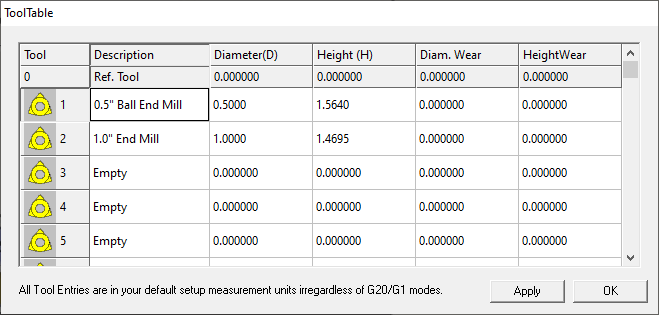
The tool offset library, sometimes called the tool offset table stores information related to the size of your cutting tools. This includes both the diameter (D offset) and tool length or height (H offset).
Offset library with H offsets on the left and D offsets on the right
The D offset and H offset values allow the machine to compensate for the size of the cutting tool and accurately machine the part.
Offsets and your cutting tools
Two of the most important characteristics of your cutting tools are their length and diameter.
These two characteristics are stored as H (height) and D (diameter) offsets.
Knowing these two values and storing them in your offset library allows the machine to adjust for the size of the cutter when running the program.
Without these adjustments using height (H) and diameter (D) offsets, the program would need to be rewritten for each new tool. Not the most efficient way to machine parts.
The value of the H offset is the distance between the end of the spindle and the end of the cutting tool.
The H code is used to select the H offset stored in the offset library when tool length compensation is turned on with the G43 code.
The D offset value is a number stored in the offset library that tells the CNC the size (diameter) of the cutting tool.
Once the machine knows the size of the cutter it can adjust how it runs the program based on that size.
Frequently asked questions about the T code
How is the T code used differently on mills vs lathes
As stated above, most CNC milling programs will use more than one tool to complete the machining of a workpiece.
Therefore, using the T code for tool changes is necessary.
On lathes, the T change is used less often because the same cutter can perform many turning operations.
However, operations such as parting-off, threading, and drilling require specific tools. The number of tools allowed on a CNC lathe depends on the number of cutters that fit in the machine’s turret.
What does T0X.0X mean?
You may see some codes that have two numbers separated by a dot along the T code (e.g. T01.01).
This formatting exists because some controllers such as Fanuc allow different offsets to be assigned to the same tool.
Depending on the type of operation performed by the tool, you may need to change its offset values. T01.01 is tool #1, offset 1. T01.02 would be tool #1, offset 2.
Ready to master CNC programming?
Try the free 30 minute intro course to see how simple and easy G code can be. Take the shortcut to becoming a G Code Master today!
To understand the coordinate system used by CNC machines, you need to first understand a few terms and concepts.
Coordinates
A coordinate is a location given in one or more axes.
Axis or plural axes
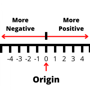
An axis is a straight line.
Along this straight line, each axis has a positive and a negative side.
The negative side continues on forever with larger and larger negative numbers. -1, -10, -99, -20,346 on til negative infinity.
On the other end of the axis are larger and larger positive numbers. 1, 5, 24, 578, 356,728 and on til positive infinity.
The two sides of the axis are separated by a center point.
At the center point the value of the axis is 0. This is called the origin.
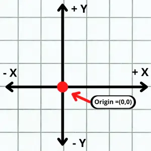
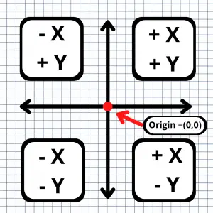
Where the X and Y axes cross is the XY origin
Origin
The origin is the zero location of one or more axes.
Typically, when talking about origins we are referring to the zero location of multiple axes.
CNC mills are usually 3 axis machines and lathes are 2 axis. Both types of machines can have more axes but let’s keep things simple.
Less axes are usually easier to understand so let’s start with 2 axis coordinates.
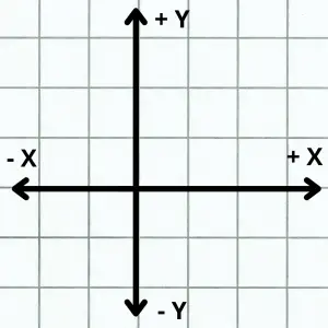
With two axes, the origin would be the (0,0) location.
The is the location where the two straight line axes cross. This could be any two axes (XY, YZ, XZ) but generally we are referring to the X and Y axes. (0,0) is (X=0, Y=0).
Note that the two axes are perpendicular, or at 90 degrees to each other.
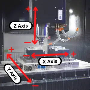
When talking about three axes, we are referring to the X, Y and Z axes.
When working with three dimensional coordinates, the origin is the spot where all three axes meet.
This is the (0,0,0) location.
Each of the axes are still perpendicular to each other. The order of axes is the same as before with the Z axis added on so (0,0,0) is (X=0, Y=0, Z=0).
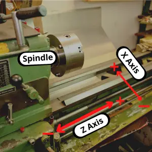
A 2 axis lathe
A 3 axis mill
Plane
A plane is a two-dimensional flat surface.
The most common one when talking about CNC machines is the XY plane. The XY plane is shown as the grid in the picture above.
The plane consists of all the possible coordinate location combinations possible in the X and Y axes.
There are three different types of plane combinations: XY, YZ, and XZ, and each plane has four quadrants with corresponding negative and positive values, two axes and an origin.
Quadrant
A quadrant is an area of the coordinate system plane. The four quadrants are shown below.
Quadrant 1 has positive X and positive Y values.
Quadrant 2 has negative X and positive Y values.
Quadrant 3 has negative X and negative Y values.
Quadrant 4 has positive X and negative Y values.
CNC machinists will want to pay attention to what happens when their machines switch quadrants.
Often changing the direction of travel from one direction to another will result in small defects or unintended features on the workpiece depending on the quality of the CNC machine.
Understanding Cartesian coordinates on a CNC machine
Usually, an easy way to understand the coordinate system for your CNC machine is to follow the Right-Hand Rule.
Hold your hand out palm up with your thumb and index finger pointed outwards, and your middle finger pointed upwards.
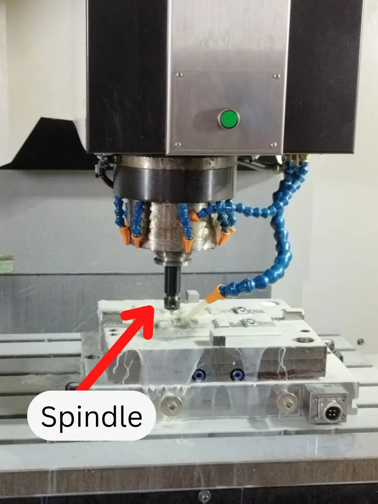
Place your hand in front of your CNC machine, aligned with the machine’s spindle, and you’ll see the axes line up perfectly.
The thumb is the X-axis.
The index finger is the Y-axis.
The middle finger is the Z-axis.
The three fingers point to the positive side of each axis. The negative side is in the opposite direction.
The thumb and index finger make an L shape and the middle finger is pointed straight up
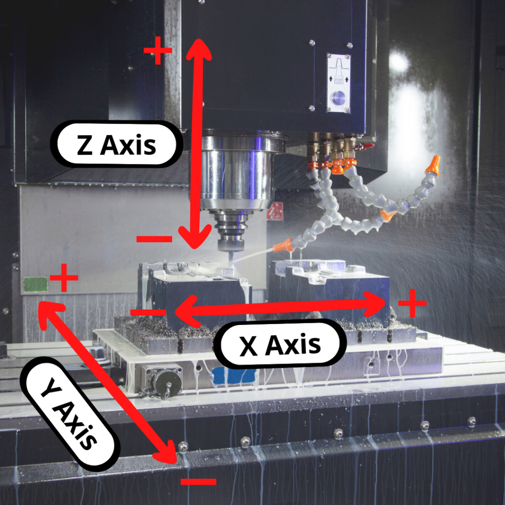
Let’s compare that to our 3 axis mill to see how they line up.
How are coordinates used in CNC machining?
Most CNC machines use a conventional cartesian coordinate system and assign the order of axes movement as follows:
X-axis allows movement “left” and “right”
Y-axis allows movement “forward” and “backward”
Z-axis allows movement “up” and “down”
However, there are a few exceptions to this rule, that will depend on the machine model or manufacturing company.
Some machines can switch the Z and Y axis, which can lead to confusion. Be sure to check all these details in your machine’s manual.
Movement in the coordinate system is related to the movement of your cutting tool. Many times, the cutting tool may not move in one or more axes but instead the control will move the table to act as if the tool moved.
Machine reference point
Every CNC machine has its own origin point or Home location that will serve as the machine’s coordinate system’s origin.
The machine reference point is a known point for the CNC machine.
The CNC control allows you to do this to make the program easier to create and understand.
Work coordinate system
A work coordinate system sets a new origin location for the machine to use when running the CNC program.
You wouldn’t want to program to random coordinate locations in your machine. You also wouldn’t want to make a new program every time you wanted to make the same part on a different CNC machine.
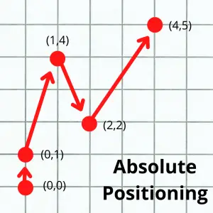
There are exceptions but most CNC programs are mainly written using absolute coordinates.
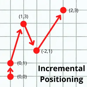
The other type of coordinates that can be used are incremental coordinates.
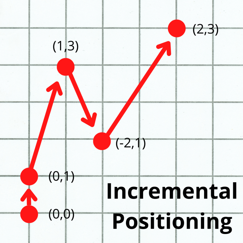
Incremental coordinates have a constantly changing origin location. Each time the CNC machine moves to a new location, that location becomes the origin.
In other words, each new move is relative to the machine’s current location.
Incremental coordinates are set using the G91 code in a CNC program. They are usually reserved for specific, repetitive features such as a series of holes that need to be drilled or something similar.
The pictures above show the same machine movement in the two different positioning modes. The locations given to the machine are given in parentheses ( ).
Most beginners don’t need to be too concerned with polar coordinates, but it is still helpful to be aware that they exist.
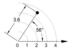
Polar coordinates are another way of specifying machine locations, like Cartesian coordinates.
Instead of X, Y and Z locations, polar coordinates use a radius, an angle, and a Z location.
Polar coordinates vs cartesian coordinates
Polar coordinates make calculations easier with circular motion, arcs, and circular paths.
On the other hand, Cartesian coordinates make linear movement easier to comprehend, and it is far more commonly used.
CNC machines are set to operate with a cartesian system by default. However, most CNC machines and controls include the option to use polar coordinates if needed.
CNC machines with multiple axes
Hobbyist CNC machines usually work with three axes (X, Y, & Z) as explained above.
Industrial grade machines can often be found with one or more additional axes. The most common is the addition of a rotary 4th axis.
4th, 5th and 6th axis machines are not uncommon.
Each of these axes rotates around one of the first 3 axes. The 4th axis rotates around X. The 5th around Y. The 6th around Z.
Ready to master CNC programming?
Try the free 30 minute intro course to see how simple and easy G code can be. Take the shortcut to becoming a G Code Master today!
The G54 command tells the CNC machine where your part is located.
To put it differently, the G54 code sets the work offset zero location to be used currently in your CNC program.
On most CNC machines, the G54 through G59 codes are for selecting these work offsets or work coordinate systems. G54 is the first code in this group and the most frequently used work offset G code.
These work offset codes (G54-G59) are each matched to coordinate locations which have been set in the CNC machine’s offset library.
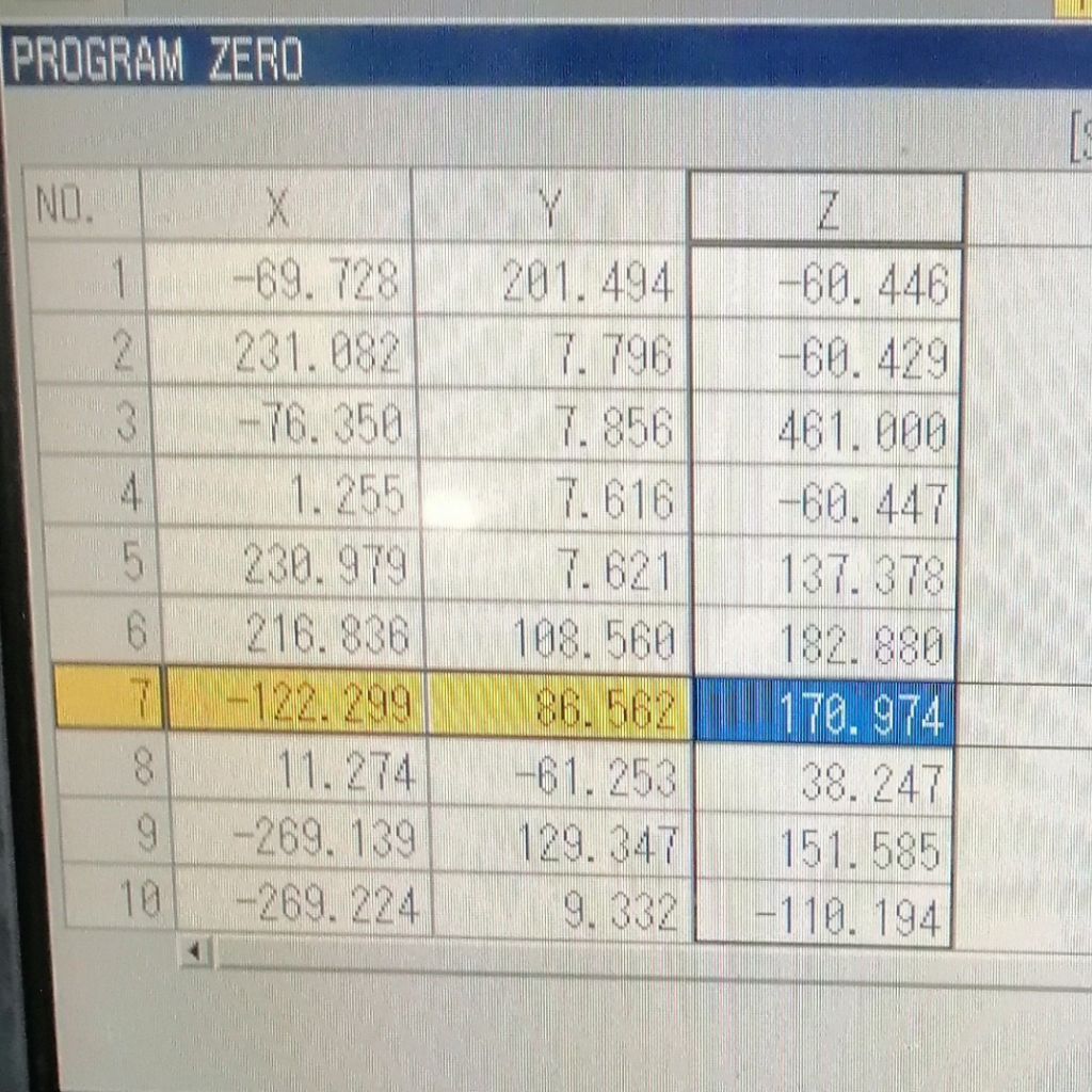
Work offset locations
Selecting a work offset code tells the CNC machine which work coordinate system to use. The coordinate locations tell the machine where the zero location is. This is the location where the X, Y, and/or Z coordinate values = zero.
G54 is a modal command
Once the G54 work offset code is used, all sizes and locations in the program will be relative to the zero location of the part until the offset is switched to a different work offset code such as G55 or G56.
This type of G code is called a modal command.
Modal commands remain in effect until they are canceled. This is true even if you restart your program.
Until you cancel the command or change it, the modal command G54 will stay in effect.
Obviously, this can cause trouble if you aren’t paying attention.
For this reason, most CNC programs will be created with start-up or safety commands. The safety commands make sure that the machine is always in the correct modes and this includes having the correct work offset chosen.
Ready to master CNC programming?
Try the free 30 minute intro course to see how simple and easy G code can be. Take the shortcut to becoming a G Code Master today!
All of the CNC codes from G54 to G59 act the same. They are all work offsets.
Everything in this article that applies to the G54 command also applies to all of the other work offsets including G55-G59.
Work offsets work like presets on your radio, except you store a location instead of a radio frequency. You can then call it up quickly and switch between them as needed.
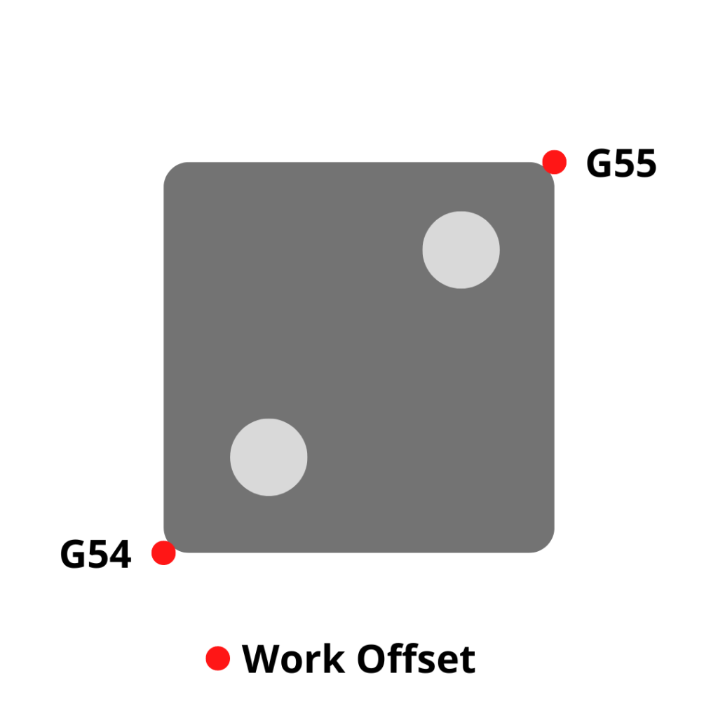
This makes operations such as referencing different sides of a part or machining multiple parts at once easier.
Two work offsets being used to drill holes on a single part
Each of these commands is modal so they will stay on until turned off or changed.
The picture below shows how multiple work offsets can be set in a CNC and how they compare to the machine zero location.
When to use a G54 code
A G54 code can be found at any point within the program but the most likely location is at the start of the program or at the start of a new section of code.
Example time!
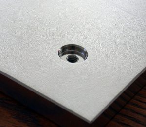
Imagine you have a part that you want to drill holes in and then counterbore the same holes.
A hole with a counterbore
In the program there will be a section of code for drilling the holes and a section of code for counterboring them.
Even though those operations both use the G54 offset, the G54 command would be given at the start of each of these sections of code.
This allows the programmer or operator to make sure the correct work offset mode is active.
Our imaginary example program is shown below.
At times, CNC programs might be run out of sequence.
If the program didn’t call out the necessary modes (in this case, the correct work offset) at the start of each section, then bad things can happen when the machine starts to perform an operation based off a different work offset/location.
In our example above with the holes and counterbores, imagine you finish the L&W roughing portion of the code and you check the holes only to find out they are undersize.
Time to make them bigger.
To do this you decide to only run the hole section of the code. This saves time compared to running the whole program right?
If you haven’t called out the G54 command in the hole section of the code, then the machine will continue using the G55 work offset that was used for the L&W roughing.
This can definitely end up with a crashed machine and/or damaged parts.
For this reason, safety lines are included in the CNC program at the start of each section.
The CNC machine needs to have the necessary modes set before any machining operation and the correct work offset is one of those modes.
Which work offset is the most commonly used?
The most common CNC work offset is the first one, G54.
Other work offsets are G55-G59.
Some machines may have more, but G54-G59 are the ones found on almost all CNC machines.
CNC codes that are similar to G54
G53 – Machine coordinate system
G53 is used to send the machine to a location based on the machine zero.
Typically, this is the home/return position for the machine.
Unlike G54, the G53 command is not modal. The G53 code only affects the line it is used on. It is a one-time use code.
This is a handy code to use, but not all machines have it. Keep in mind that older machines, and even some of the newer ones might think the code is something else.
Not all CNC codes are universal across the different manufacturers .
You can expect that G54 will be the same on every machine, but I can’t say the same for G53.
G28 – Machine coordinate system
The G28 code is used to send the machine to a location and then to the machines zero location in one or more of axes.
How does G10 affect G54 and other work offsets
A G10 code is used to change an offset value.
The format for using G10 looks like this:
G10 L2 P1 X1.5 Y2.3 Z 3.0
The L code is for the offset type.
The P code is the offset number.
G10 codes are not something for beginners. Also, the code format isn’t the same across all CNC controls. It is important to know how your machine will react to a G10 codes. Consult your manual.
Ready to master CNC programming?
Try the free 30 minute intro course to see how simple and easy G code can be. Take the shortcut to becoming a G Code Master today!
The G49 code is not a required part of your CNC program.
It is rare that you would want to move the tip of your spindle to an exact location. You will almost always have a cutting tool in the spindle that you will want to account for.
This means the G49 code is not used often. It is more important to make sure you have the correct tool and offset selected.
Some programmers choose to include the G49 code as part of their safety block of code.
Others skip it and just make sure to call out the correct offset for their tool at the start of a new section of code.
As long as you switch to the correct offset for the currently loaded tool, then there is no need to cancel tool length compensation with the G49 code.
What to think about when using a G49 code?
Different machines can interpret the G49 code in varying ways.
When the G49 code is used, some machines will immediately move the end of the spindle to the location the end of the cutting tool was previously in.
If you aren’t in a safe location with enough clearance, the machine could crash. That’s never good!
If you plan to use a G49 code then make sure you understand how your CNC will react. Check your manual!
Other CNC cancel commands
Code
Description
G40
Cancel cutter compensation
G49
Cancel tool length compensation
G50
Cancel scaling
G67
Cancel custom macro call
G69
Cancel rotation
G80
Cancel canned cycles
Codes that are similar to G49
There are multiple commands that will cause the machine to act very similar to when a G49 codes is used.
Using the M30 code, the reset command or an H0 offset will cause the CNC machine to cancel tool length compensation.
Ready to master CNC programming?
Try the free 30 minute intro course to see how simple and easy G code can be. Take the shortcut to becoming a G Code Master today!
Welcome to our comprehensive guide to using the G00 CNC code. Whether you’re a beginner learning CNC programming or an experienced machinist, understanding the G00 CNC code is extremely important.
In this guide, we’ll break down everything you need to know about this rapid traverse command, including how, when, and why to use it.
What does a G00 code do?
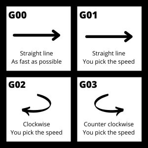
G00 sets the CNC movement mode to rapid traverse, sometimes called rapid travel.
G00 controls the speed of the machine’s motion.
This code is used to move the CNC table and/or spindle around in a straight line (linearly) at the maximum speed.
When G00 is used, the machine ignores any feed rate set with the F code and instead goes as fast as possible.
Any combination of 1 or more of the machines axes can be moved in rapid mode. This includes the X, Y and Z axes.
Some people get confused about whether the extra 0 is required to be included with an G00 code.
To clear this up, there is no need to include the extra zero in the code. The CNC machine will read the code the same. It really is just a matter of preference.
Often you will see the full G00 code used in textbooks or other reference materials. In practice though, many prefer the shortened G0 code in their programs.
If you are working on your own, then go with whichever format you prefer. If you work in a bigger shop, make sure to stick to the format that the business has been using.
When to use the G00 code
G00 codes are used when the CNC programmer wants to move the tool very quickly. This happens at many points throughout a program.
Rapid positioning with G00 moves the machine at full speed. This allows the program to be run faster and decreases the part cycle time which means parts can be made faster.
G00 should only be used when there is no cutting action happening.
Using G00 while cutting your part would not give you good control over the cutting conditions and would most likely damage your part and/or your machine.
Use the G00 code to move the cutter to the location where it will start cutting or to other locations in the CNC such as the tool change position.
Other codes used with G00
The codes below are used with the G00 code or commonly found very close to a G00 command in the CNC program:
G00 is a simple code. You only need to specify the stop location for the movement.
Because G00 is a modal code, you don’t need to specify it on every line of code. If the next line of code after the one above was X4.0 Y5.0 Z6.0 then the machine would still move to the location in rapid mode. Because it’s modal it stays on until switched to another mode.
How to turn off a G00 code
There isn’t a specific cancel command for G00 like there is for canned cycles.
Instead, to turn G00 off you will need to switch it to another code in the same group of movement codes.
Using any of these codes will turn G00 rapid movement off and switch to the new movement mode.
What to think about when using a G00 code
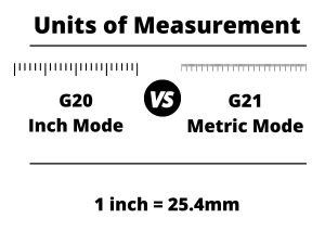
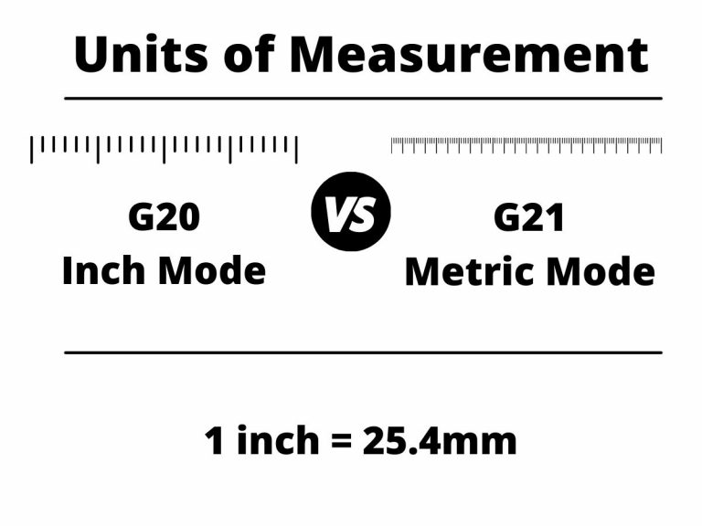
Units
First, make sure you know what units you are working in.
Moving 10 inches instead of 10 millimeters is a big difference. A G20 (inches) or G21 (mm) code should identify the units you are working in before your G00 code.
Absolute vs incremental positioning mode
The second thing to know is how the machine will understand position locations.
This is determined by whether you are working in absolute (G90) or incremental (G91) coordinates. The most recent G90 or G91 code in the program will determine which mode you are in.
Absolute positioning will move from a set zero location, such as your machines home location or a specified zero location on your part.
Incremental positioning will move relative to the machine’s current position.
The images below show the difference between the absolute and incremental positioning modes. The numbers in parentheses are the locations given to the the machine to make the move.
Notice how in absolute mode, all locations are relative to a single location, usually either the workpiece zero or machine home location.
In incremental mode, all locations are relative to the machine’s current location.
Start and stop locations
Make sure you understand the path that the tool will take from it’s start location to the new location.
Check where you are currently position wise (X, Y & Z location), where you will be moving to, and if there is anything in between the two locations.
The G00 code will move the machine very quickly to the new location. You don’t want anything in the way or to miscalculate your stop point.
Crashing your machine is never a good time.
Machine movement
There are many different CNC machines throughout the world. Unfortunately, they don’t all behave exactly the same. For this reason you need to make sure you know your machine when it comes to how it moves, especially when it comes to rapid movement.
Some machines will move all 3 axes at once. Some will rapid one at a time.
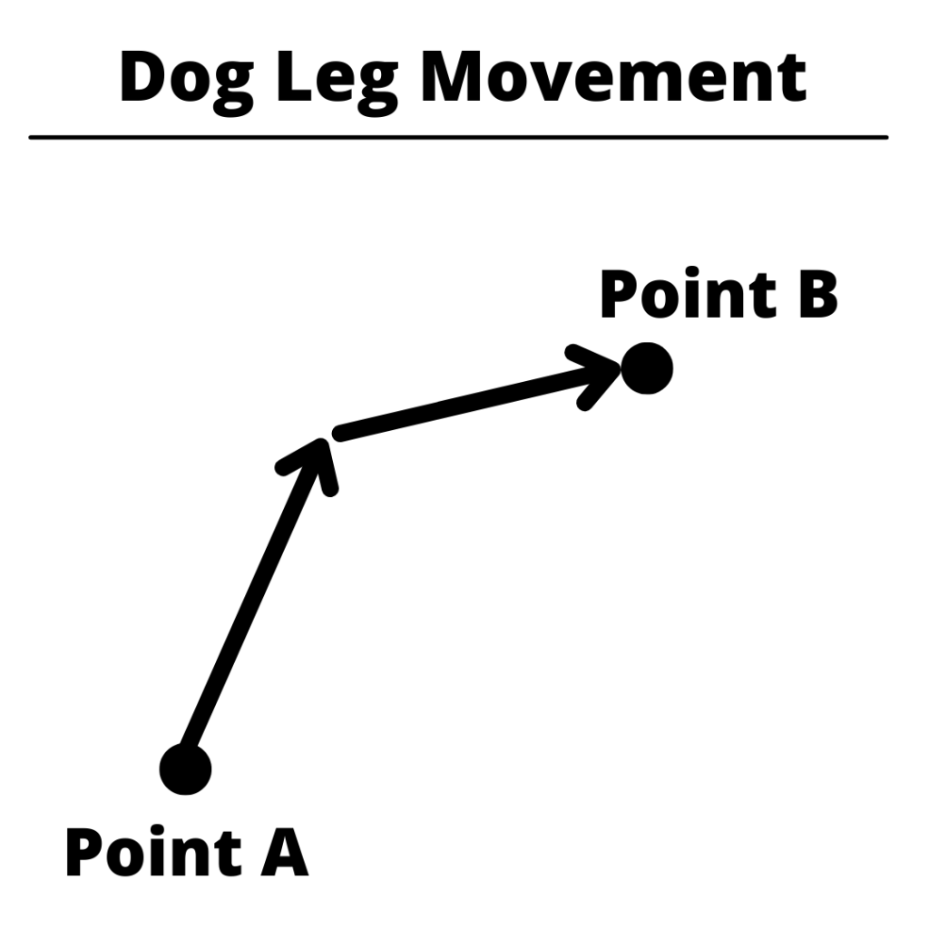
Some machines will move the different axes at different speeds causing a “dog leg” movement where the machine doesn’t move in a single straight line.
Most machines will move all 3 at once, but make sure you know the path your CNC will take when using the G00 code.
It’s important to understand how you individual CNC machine will move because you need to make sure there isn’t something that the CNC will crash into in that path.
G00 [Rapid Travel] vs G01 [Linear Interpolation]
G01 is a very similar command. It also controls straight line movement, otherwise known as linear interpolation, of the CNC machine.
The difference between the two is that G01 will not move at maximum speed and will instead move at the last feed rate listed in the CNC program using the F command.
G01 is used for cutting motions. G00 is not.
CNC codes that are similar to G00
Note that all the movement codes listed below are modal. This means they will stay in the movement mode identified by the code until switched to a different mode.
Welcome to our comprehensive guide to using the G01 CNC code. Whether you’re a beginner learning CNC programming or an experienced machinist, understanding the G01 CNC code is extremely important.
In this guide, we’ll break down everything you need to know about this linear interpolation command, including how, when, and why to use it.
What does a G01 code do?
G01 sets the CNC movement mode to straight line movement, otherwise known as linear interpolation.
The G01 code is used to move the CNC axes (X, Y, & Z) around in a straight line around at a feed rate specified with the F command.
Some people get confused about whether the 0 is required to be included in a G01 code.
To clear this up, there is no need to include the extra zero in the code. The CNC machine will read the code the same. It really is just a matter of preference.
Often you will see the full G01 code used in textbooks or other reference materials. In practice though, many prefer the shortened G1 code in their programs.
If you are working on your own, then go with whichever format you prefer. If you work in a bigger shop, make sure to stick to the format that the business has been using.
When to use a G01 code?
G01 codes are found in the lines of the program where the material is being cut.
The G01 code allows the programmer to specify the location where the tool will move to.
Once the G01 code is used, the machine will move to any XYZ locations given in a straight line at the set feed rate.
Because G01 is a modal code, you don’t need to specify it on every line of code.
If the next line of code after the one above was:
X4.0 Y5.0 Z6.0
then the machine would still move to the location in a straight line at the set feed rate. Because it’s modal, it stays on until switched to another mode.
The feed rate will also remain the same until it is changed and isn’t required to be on every line. This means that the feed rate can be set before the G01 code is used as well.
How to turn off the G01 code
There isn’t a specific cancel command for G01 like there is for canned cycles. Instead, to turn G01 off you will need to switch it to another code in the same group of movement codes.
Using any of these codes will turn G01 linear interpolation off and switch to the new movement mode.
What to think about when using a G01 code?
Units
First, make sure you know what units you are working in.
Moving 10 inches instead of 10 millimeters is a big difference. A G20 (inches) or G21 (mm) code identifies the units you are working in when making a move with your G01 code.
Absolute vs incremental mode
The second thing to know is how the machine will understand position locations.
This is determined by whether you are working in absolute (G90) or incremental (G91) coordinates. The most recent G90 or G91 code in the program will determine which mode you are in.
Absolute positioning will move from a set zero location such as your machines home location or a specified location on your part.
Incremental positioning will move relative to your current position.
The images below show the difference between the absolute and incremental positioning modes. The numbers in parentheses are the locations given to the the machine to make the move.
Notice how in absolute mode, all locations are relative to a single location, usually either the workpiece zero or machine home location.
In incremental mode, all locations are relative to the machine’s current location.
Start and stop locations
Lastly, make sure you understand the path that the tool will take from it’s start location to the new location.
Check where you are currently position wise (X, Y & Z location), where you will be moving to, and if there is anything in between the two locations.
The G01 code will move the machine in a straight line to your new location.
You don’t want anything in the way or to miscalculate your stop point. Clamps or vises can be easy to forget about and run into.
Crashing your machine is never a good time.
G01[linear interpolation] vs G00[rapid travel]
G00 is a straight line movement code similar to G01.
There is one big difference between the two codes:
Note that all the movement codes listed below are modal. This means they will stay in the movement mode identified by the code until switched to a different mode.
Welcome to our comprehensive guide to using the G02 CNC code. Whether you’re a beginner learning CNC programming or an experienced machinist, understanding the G02 CNC code is extremely important.
In this guide, we’ll break down everything you need to know about this circular interpolation command, including how, when, and why to use it.
What does a G02 code do?
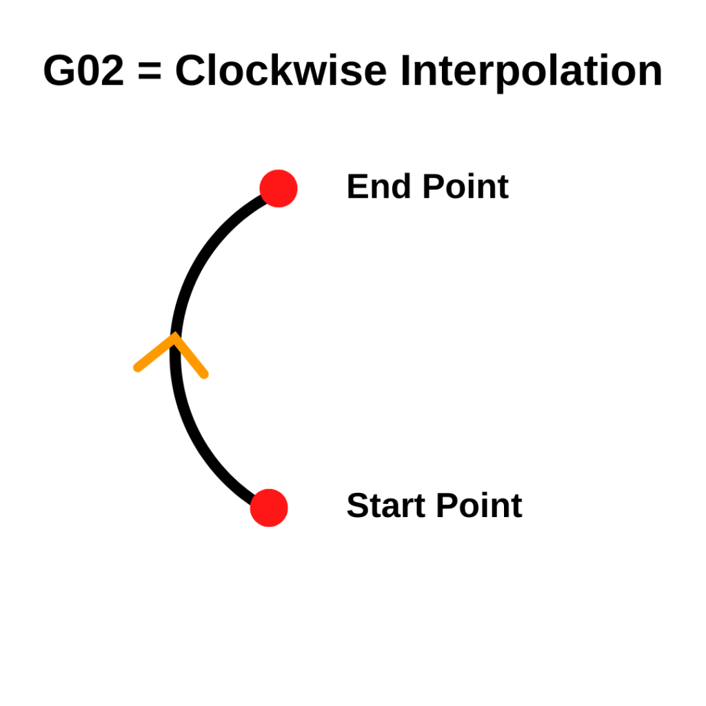
G02 sets the CNC movement mode to clockwise circular movement, otherwise known as circular interpolation.
You know how when you zoom in real far on a photo, it starts to look all pixelated?
Circular interpolation is kind of like that. When we zoom in real close and look at how the machine is moving, we see it isn’t so smooth.
A series of small steps that look like a circle
While it may look like your CNC machine is moving in a perfect circle, it is actually moving in a series of small steps that look like a circle. This is called interpolation.
Basically, your CNC is doing the best it can to mimic a perfect circle.
You don’t need to do anything differently, it’s just good to know what we mean by interpolation.
G02 [clockwise circular interpolation] vs G03 [counterclockwise circular interpolation]
Everything that applies to the G02 code applies to the G03 code as well.
The only difference between the two is the direction of movement.
Some people get confused about whether the 0 is required to be included in a G02 code.
To clear this up, there is no need to include the extra zero in the code. The CNC machine will read the code the same. It really is just a matter of preference.
Often you will see the full G02 code used in textbooks or other reference materials. In practice though, many prefer the shortened G2 code in their programs.
If you are working on your own, then go with whichever format you prefer. If you work in a bigger shop, make sure to stick to the format that the business has been using.
When to use a G02 code?
G02 codes will usually be in the lines of the program that are used to cut the part.
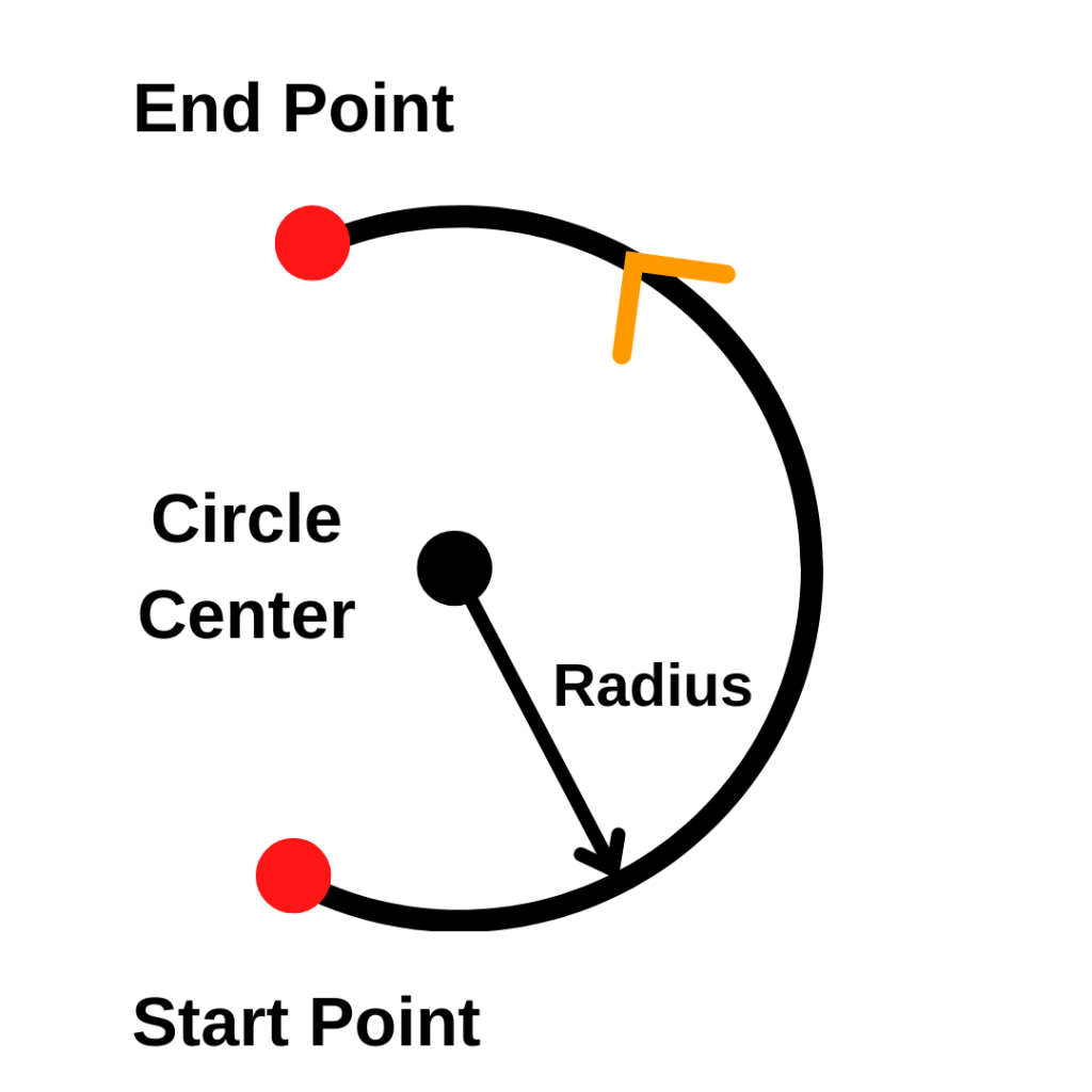
The G02 code allows the programmer to cut a full circle or portion of a circle.
An R code is used as well to tell the machine what size radius to move along. Some CNC programs will use IJK codes instead of an R code to describe the circular move.
Other codes used with G02
The codes below are used with the G02 code or commonly found very close to a G02 command in a CNC program:
Once the G02 code is used the machine will move to any XYZ locations given in a circular movement going clockwise along the given radius size and at the set feed rate.
Because G02 is a modal code, you don’t need to specify it on every line of code.
If the next line of code after the one above was:
X7.0 Y1.0 R0.5
then the machine would still move to the location in a circle at the set feed rate. Because it’s modal it stays on until switched to another mode.
The feed rate will also remain the same until it is changed and isn’t required to be on every line. This means that the feed rate can be set before the G02 code is used as well.
How to turn off the G02 code
There isn’t a specific cancel command for G02 like there is for canned cycles. Instead to turn G02 off you will need to switch it to another code in the same group of movement codes.
Using any of these codes will turn G02 clockwise circular interpolation off and switch to the new movement mode.
What to think about when using a G02 code?
Units
First, make sure you know what units you are working in.
Moving 10 inches instead of 10 millimeters is a big difference. A G20 (inches) or G21 (mm) code should identify the units you are working in before your G02 code.
Absolute vs incremental mode
The second thing to know is how the machine will understand position locations.
This is determined by whether you are working in absolute (G90) or incremental (G91) coordinates. The most recent G90 or G91 code in the program will determine which mode you are in.
Absolute positioning will move from a set zero location such as your machines home location or a specified location on your part.
Incremental positioning will move relative to your current position.
The images below show the difference between the absolute and incremental positioning modes. The numbers in parentheses are the locations given to the the machine to make the move.
Notice how in absolute mode, all locations are relative to a single location, usually either the workpiece zero or machine home location.
In incremental mode, all locations are relative to the machine’s current location.
Start and stop locations
Lastly, make sure you understand the path that the tool will take from it’s start location to the new location.
Check where you are currently position wise (X, Y & Z location), where you will be moving to and if there is anything in between the two locations.
The G02 code will move the machine in a circular arc to your new location. You don’t want anything in the way or to miscalculate your stop point. Clamps or vises can be easy to forget about and run into.
Crashing your machine is never a good time.
CNC codes that are similar to G02
Note that all the movement codes listed below are modal.
This means they will stay in the movement mode identified by the code until switched to a different mode.
Welcome to our comprehensive guide to using the G03 CNC code. Whether you’re a beginner learning CNC programming or an experienced machinist, understanding the G03 CNC code is extremely important.
In this guide, we’ll break down everything you need to know about this circular interpolation command, including how, when, and why to use it.
What does a G03 code do?
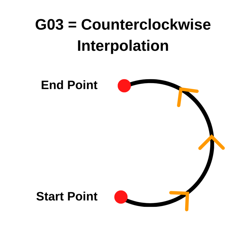
G03 sets the CNC movement mode to counterclockwise circular movement, otherwise known as circular interpolation.
You know how when you zoom in real far on a photo, it starts to look all pixelated?
Circular interpolation is kind of like that. When we zoom in real close and look at how the machine is moving, we see it isn’t so smooth.
A series of small steps that look like a circle
While it may look like your CNC machine is moving in a perfect circle, it is actually moving in a series of small steps that look like a circle. This is called interpolation.
Basically, your CNC is doing the best it can to mimic a perfect circle.
You don’t need to do anything differently, it’s just good to know what we mean by interpolation.
G03 [counterclockwise circular interpolation] vs G02 [clockwise circular interpolation]
Everything that applies to the G03 code applies to the G02 code as well.
The only difference between the two is the direction of movement.
Some people get confused about whether the 0 is required to be included in a G03 code.
To clear this up, there is no need to include the extra zero in the code. The CNC machine will read the code the same. It really is just a matter of preference.
Often you will see the full G03 code used in textbooks or other reference materials. In practice though, many prefer the shortened G3 code in their programs.
If you are working on your own, then go with whichever format you prefer. If you work in a bigger shop, make sure to stick to the format that the business has been using.
When to use a G03 code?
G03 codes will usually be in the lines of the program that are used to cut the part.
The G03 code allows the programmer to cut a full circle or portion of a circle.
An R code is used as well to tell the machine what size radius to move along. Some CNC programs will use IJK codes instead of an R code to describe the circular move.
Other codes used with G03
The codes below are used with the G03 code or commonly found very close to a G03 command in a CNC program:
Once the G03 code is used the machine will move to any XYZ locations given in a circular movement going counterclockwise along the given radius size and the set feed rate.
Because G03 is a modal code, you don’t need to specify it on every line of code.
If the next line of code after the one above was:
X7.0 Y1.0 R0.5
then the machine would still move to the location in a circle at the set feed rate. Because it’s modal, it stays on until switched to another mode.
The feed rate will also remain the same until it is changed and isn’t required to be on every line. This means that the feed rate can be set before the G03 code is used as well.
How to turn off a G03 code
There isn’t a specific cancel command for G03 like there is for canned cycles. Instead to turn G03 off you will need to switch it to another code in the same group of movement codes.
Using any of these codes will turn G03 counterclockwise circular interpolation off and switch to the new movement mode.
What to think about when using a G03 code?
Units
First, make sure you know what units you are working in. Moving 10 inches instead of 10 millimeters is a big difference.
A G20 (inches) or G21 (mm) code should identify the units you are working in before your G03 code.
Absolute vs incremental mode
The second thing to know is how the machine will understand position locations.
This is determined by whether you are working in absolute (G90) or incremental (G91) coordinates. The most recent G90 or G91 code in the program will determine which mode you are in.
Absolute positioning will move from a set zero location such as your machines home location or a specified location on your part.
Incremental positioning will move relative to your current position.
The images below show the difference between the absolute and incremental positioning modes. The numbers in parentheses are the locations given to the the machine to make the move.
Notice how in absolute mode, all locations are relative to a single location, usually either the workpiece zero or machine home location.
In incremental mode, all locations are relative to the machine’s current location.
Start and stop locations
Lastly, make sure you understand the path that the tool will take from it’s start location to the new location.
Check where you are currently position wise (X, Y & Z location), where you will be moving to and if there is anything in between the two locations.
The G03 code will move the machine in a circular arc to your new location. You don’t want anything in the way or to miscalculate your stop point. Clamps or vises can be easy to forget about and run into.
Crashing your machine is never a good time.
CNC codes that are similar to G03
Note that all the movement codes listed below are modal. This means they will stay in the movement mode identified by the code until switched to a different mode.
To provide the best experiences, we use technologies like cookies to store and/or access device information. Consenting to these technologies will allow us to process data such as browsing behavior or unique IDs on this site. Not consenting or withdrawing consent, may adversely affect certain features and functions.
Functional
Always active
The technical storage or access is strictly necessary for the legitimate purpose of enabling the use of a specific service explicitly requested by the subscriber or user, or for the sole purpose of carrying out the transmission of a communication over an electronic communications network.
Preferences
The technical storage or access is necessary for the legitimate purpose of storing preferences that are not requested by the subscriber or user.
Statistics
The technical storage or access that is used exclusively for statistical purposes.The technical storage or access that is used exclusively for anonymous statistical purposes. Without a subpoena, voluntary compliance on the part of your Internet Service Provider, or additional records from a third party, information stored or retrieved for this purpose alone cannot usually be used to identify you.
Marketing
The technical storage or access is required to create user profiles to send advertising, or to track the user on a website or across several websites for similar marketing purposes.