G99 CNC Code Explained: An Easy Intro for Beginners [Return to R Plane]

What does the G99 code do?

The G99 code is a modal command that tells the cutting tool to move back to the R plane after finishing a canned cycle operation.

G99 is a very important code because it allows you to shorten the time needed to move your cutter around when machining.

The alternative to G99 is the G98 code

G98 also controls the movement of the machine after finishing a canned cycle.

Learn CNC Programming – It’s Easier Than You Think!

Learning G Code doesn’t have to be difficult…

If you know what to focus on.

Join our simple, easy-to-follow course, “G Code Made Easy: CNC Programming for Beginners“. We walk you through all the important codes – with simple explanations and real-world examples.

Want to become a super-skilled CNC programmer? Join now to take the shortcut to becoming a G Code Master today!

Make Learning G Code Easy

G99 vs G98

Both codes are used to perform similar actions.

The difference is that they lift the tool to different heights when finishing a canned cycle process.

The G98 code lifts the tool back to the initial Z position which the machine was at when starting the canned cycle. This is safer option if you are unsure.

G99 travels back to the R plane instead. The R plane is closer to the part which can potentially cause problems if there are obstacles close to the part such as fixtures or clamps.
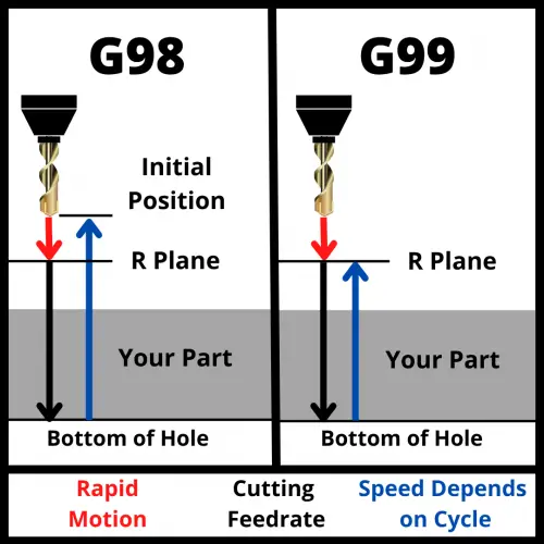
visualization of how a cnc machine moves using g98 and g99 codes shows motion of travel for the machine

Other codes and parameters used with a G99 code

When using the G99 code you should consider all of the following items that can be included as part of the code:

The feed rate will depend on the material that is being cut and the diameter of the drilling tool that you are using.

The retract (R) plane or clearance level refers to the plane height where the tool can move safely from one hole to another. The R value should be set so the machine will clear any and all obstacles including clamps, fixtures and the part itself.

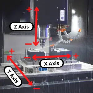
X and Y are the location of the hole. Z controls the depth of the hole.

G99 code format

Using the parameters above, the format for using a G99 code is:

G81 X0 Y0 R0 Z1 F5 G99

G81 is the canned cycle. This can be replaced with any other canned cycle as needed.

The rest of the codes are as listed in the parameters section above. The X, Y and F codes are not required. Often, the X and Y codes will be placed on the previous line.

It is good practice to include the feedrate (F) code.

What to think about when using G99

When using the G99 command, think about the obstacles that could be in the way of the movement of your cutter.

Using G99 will move your cutter to the R plane specified with the R code. 

The R plane will usually be set close to the top of the part to make the moves shorter which takes less time. 

This is great for reducing cycle time but not great for avoiding obstacles.

Common obstacles in the machine are:

  • The workpiece
  • Clamps
  • Fixtures
  • Other tooling

Reducing the cycle time is great for industrial CNC machines, but for hobbyists this isn’t as much of a concern. 

Unless you are trying to maximize the output of your machine, G98 is a safer option.

G99 code example

N1 Z5.0 M08;

N2 G82 G99 Z-3.0 R1.0 P500 F50.0;

N3 X10.0;

N4 G98 X20.0;

N5 G99 X10.0;

N6 G80;

The first line (N1) brings the drill down to 5mm above the material surface and turns on the coolant with M08.

Then, the second line (N2) sets the counterbore canned cycle with G82 and tells the machine to return to the R plane where Z = 1.0.

The Z-3.0 is the depth of the counterbore and P500 is the dwell time when the machine reaches the bottom of the hole in milliseconds.

F is feed rate in mm/min.

Line 3 (N3) tells the machine to move the X axis of the machine to the X=10.0 location. Because the canned cycle is a modal code, another counterbore will be drilled to the same parameters as in line 2.

The next line (N4) drills the third hole at X=20mm. G98 tells the control to return to the initial plane. This is Z=5.0, the last Z location before starting the canned cycle. The machine will rapid back to Z=5.0 above the part surface after drilling the previous hole.

The machine drills the final hole 10mm in X from the last one, the G99 code tells the machine to rapid back to the R position instead of the initial Z position.

Lastly, on line 6 (N6) G80 turns the counterboring canned cycle off.

Frequently asked questions about the G99 code

Is G99 modal?

Yes, G99 is a modal command. 

This means it will stay on until changed to another code in the same code group or canceled. 

It will only be in effect for running canned cycles though. 

G99 has no effect on straight line movement with either G00/G01 or circular movement with G02/G03.

What does the G99 code do on a lathe?

The G99 codes is completely different when running a CNC lathe.

G99 on a lathe sets the feed rate mode to feed rate per revolution.

This means if you use a F5 command and G99 is active, the feed rate will be set to 5 inches per revolution.

G98 on a lathe sets the feed rate mode to feed rate minute.
Want to learn more about CNC G Code?

G98 CNC Code Explained: An Easy Intro for Beginners [Return to Initial Plane]

What does a G98 code do?

The G98 code is a modal command that tells the cutting tool to move back to the initial plane after finishing a canned cycle operation.

Often, CNC machines will have this command set to “on” by default.

G98 is a very important code because it allows you to avoid clamps, fixtures, and other obstacles that may be present when machining.

The alternative to G98 is G99. 

The G99 code also controls the movement of the machine after finishing a canned cycle.

Learn CNC Programming – It’s Easier Than You Think!

Learning G Code doesn’t have to be difficult…

If you know what to focus on.

Join our simple, easy-to-follow course, “G Code Made Easy: CNC Programming for Beginners“. We walk you through all the important codes – with simple explanations and real-world examples.

Want to become a super-skilled CNC programmer? Join now to take the shortcut to becoming a G Code Master today!

Make Learning G Code Easy

G98 vs G99

visualization of how a cnc machine moves using g98 and g99 codes shows motion of travel for the machine

Both codes are used to perform similar actions.

The difference is that they lift the tool to different heights when finishing a canned cycle process.

G98 lifts the tool back to the initial Z position which the machine was at when starting the canned cycle. This is safer option if you are unsure

The G99 code travels back to the R plane instead. The R plane is closer to the part which can potentially cause problems if you aren’t paying attention.  

Other codes and parameters used with the G98 code

When using the G98 code you should consider all of the following items that can be included as part of the code:

The feed rate will depend on the material that is being cut and the diameter of the drilling tool that you are using.

The retract (R) plane or clearance level refers to the plane height where the tool can move safely from one hole to another. 

The R value should be set so the machine will clear any and all obstacles including clamps, fixtures and the part itself.

X and Y are the location of the hole. Z controls the depth of the hole.

an illustration that shows the X, Y and Z axes on a CNC machine

G98 code format

Using the parameters above, the format for using a G98 code is:

G81 X0 Y0 R0 Z1 F5 G98

G81 is the canned cycle. This can be replaced with any other canned cycle as needed.

The rest of the codes are as listed in the parameters section above. The X, Y and F codes are not required. Often, the X and Y codes will be placed on the previous line.

It is good practice to include the feedrate (F) code.

What to think about when using a G98 code?

When using the G98 command, think about the obstacles that could be in the way of the movement of your cutter.

Using G98 will move your cutter to the initial plane which is the Z height at the start of the canned cycle. This is generally the safest location and should be set at a Z height above all obstacles in the machine.

Common obstacles in the machine are:

  • The workpiece
  • Clamps
  • Fixtures
  • Other tooling

You should also think about the speed of your program. 

For hobbyists, this isn’t as much of a concern. 

For industrial machines, the time it takes to move back to the initial plane instead of the R plane can add up and time is money in the machining industry.

G98 code example

N1 Z5.0 M08;

N2 G82 G99 Z-3.0 R1.0 P500 F50.0;

N3 X10.0;

N4 G98 X20.0;

N5 G99 X10.0;

N6 G80;

The first line (N1) brings the drill down to 5mm above the material surface and turns on the coolant with M08.

Then, the second line (N2) sets the counterbore canned cycle with G82 and tells the machine to return to the R plane where Z = 1.0.

The Z-3.0 is the depth of the counterbore and P500 is the dwell time when the machine reaches the bottom of the hole in milliseconds.

F is feed rate in mm/min.

Line 3 (N3) tells the machine to move the X axis of the machine to the X=10.0 location. Because the canned cycle is a modal code, another counterbore will be drilled to the same parameters as in line 2.

The next line (N4) drills the third hole at X=20mm. G98 tells the control to return to the initial plane. This is Z=5.0, the last Z location before starting the canned cycle. The machine will rapid back to Z=5.0 above the part surface after drilling the previous hole.

The machine drills the final hole 10mm in X from the last one, the G99 code tells the machine to rapid back to the R position instead of the initial Z position.

Lastly, on line 6 (N6) G80 turns the counterboring canned cycle off.

Frequently asked questions about the G98 code

Is G98 a modal command?

Yes, G98 is a modal command. 

Modal codes will stay on until changed to another code in the same code group or until they are canceled. 

It will only be in effect for running canned cycles though. G98 has no effect on straight line movement with either G00/G01 or circular movement with G02/G03.

What does the G98 code do on a lathe?

The G98 codes is completely different when running a CNC lathe.

G98 on a lathe sets the feed rate mode to feed rate per minute.

This means if you use a F100 command and G98 is active, the feed rate will be set to 100 inches per minute.

G99 on a lathe sets the feed rate mode to feed rate per revolution.

Want to learn more about CNC G Code?

G91 CNC Code Explained: An Easy Intro for Beginners [Incremental Positioning]

What does a G91 code do?

A G91 code sets the CNC to incremental positioning mode.

This means that the CNC will interpret all location values as relative to the position of the machine before making the move.

The zero location of the machine will move each time the machine moves. This can be good for repetitive work such as drilling a series of holes.

Learn CNC Programming – It’s Easier Than You Think!

Learning G Code doesn’t have to be difficult…

If you know what to focus on.

Join our simple, easy-to-follow course, “G Code Made Easy: CNC Programming for Beginners“. We walk you through all the important codes – with simple explanations and real-world examples.

Want to become a super-skilled CNC programmer? Join now to take the shortcut to becoming a G Code Master today!

Make Learning G Code Easy

G90 vs G91: CNC positioning modes

CNC machines have two positioning modes available.

They are absolute positioning using the G90 code and incremental positioning using the G91 code.

As noted above, incremental positioning with G91 will take all locations relative to the machines current location.

With absolute positioning (G90), the machine will interpret all locations as relative a static location. This will usually be the work offset zero location as set by the G54 code or the machines home location if no work offset is active.

G90 and G91 are both modal codes.

Modal codes stay active until they are either canceled or changed. For G90 and G91, there is no cancel code so the only way to change them is to call the opposite code.

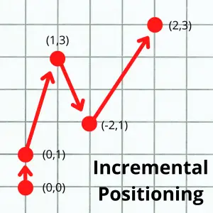
graph paper example of incremental positioning with multiple points as examples
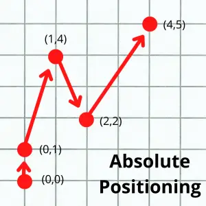
graph paper example of absolute positioning with multiple points as examples

The images above show the difference between the absolute and incremental positioning modes. The numbers in parentheses are the locations given to the the machine to make the move.

Notice how in absolute mode, all locations are relative to a single location, usually either the workpiece zero or machine home location. 

In incremental mode, all locations are relative to the machine’s current location.

When to use a G91 code

The main portion of most programs will be in absolute mode (G90).

Incremental mode (G91) is usually only used to create repetitive features such as drilling a set of holes.

G91 is a much less frequently used code compared to G90.

G90 codes are used frequently. This is because they get used as part of safety lines of code sometimes called safety block.

Safety lines are a chunk of code that is used to ensure that the machine is in the correct modes before executing a section of the CNC program.

They are used at the start of new sections of code such as when changing tools or when starting a new machining operation.

Why using a G91 code is important

Both G90 and G91 are modal commands which means that they will stay in effect until changed or canceled.

It is important to set your positioning mode in your program with either G90 (absolute mode) or G91 (incremental mode).

Imagine if you had an operation where you were going to drill a set of holes. Before you drill those holes, it would be wise to set all the necessary modes you will need to have active.

Setting the positioning mode (absolute or incremental), setting the type of units you are in (inches or mm) and turning on various compensation modes are just some of the modes that you might want to have set.

If these modes are already active, then nothing will change. No harm, no foul.

If they weren’t active and you didn’t turn them on, you might crash your machine.

When writing your CNC programs, it is critical to be in the correct positioning mode at all times. For this reason, a G90 or G91 code should be used at the start of a new section of the program.

What to think about when using a G91 code

Know where you are at and where you want to move the machine.

In other words, you need to know where the start and stop location of each move is.

The main body of most programs will be written in absolute mode (G90). This is because it is easier to visualize a part based on absolute coordinates.

Portions of a program get written in incremental mode. Often incremental mode is used when dealing with canned cycles or subprograms.

You can make your whole program in incremental mode if you wish, most people don’t though.

CNC codes that are similar to G91

We already discussed the most common code that is similar to G91. G90 sets the machine in absolute positioning mode.

The other main codes that affect positioning are G60 and G64.

G60 sets the CNC to single direction positioning mode.

The G60 code will make force the machine to approach each new location from the same direction. This decreases location errors that can occur because of backlash in the machine.

G64 is normal positioning mode. In normal positioning mode, the machine will move all axes at the same time and will approach the workpiece form whichever side is fastest.

Want to learn more about CNC G Code?

G90 CNC Code Explained: An Easy Intro for Beginners [Absolute Positioning]

What does a G90 code do?

A G90 code sets the CNC to absolute positioning mode.

This means that the CNC will interpret all location values as relative to a single zero location.

That single zero location is usually the workpiece zero location (set by a work offset such as G54) or the CNC machine zero location (home position).

Learn CNC Programming – It’s Easier Than You Think!

Learning G Code doesn’t have to be difficult…

If you know what to focus on.

Join our simple, easy-to-follow course, “G Code Made Easy: CNC Programming for Beginners“. We walk you through all the important codes – with simple explanations and real-world examples.

Want to become a super-skilled CNC programmer? Join now to take the shortcut to becoming a G Code Master today!

Make Learning G Code Easy

G90 vs G91: CNC positioning modes

CNC machines have two positioning modes available. 

They are absolute positioning using the G90 code and incremental positioning using the G91 code.

As noted above, absolute positioning with G90 will take all locations relative to a fixed zero location.

With incremental positioning (G91), the machine will interpret all locations as relative to the current location. In other words, once the machine moves to a new location, that location becomes the new zero.

G90 and G91 code are both modal. 

Modal commands stay active until it is either canceled or changed. 

For G90 and G91, there is no cancel code. The only way to change them is to call the opposite code.

graph paper example of absolute positioning with multiple points as examples
graph paper example of incremental positioning with multiple points as examples

The images above show the difference between the absolute and incremental positioning modes. The numbers in parentheses are the locations given to the the machine to make the move.

Notice how in absolute mode, all locations are relative to a single location, usually either the workpiece zero or machine home location. 

In incremental mode, all locations are relative to the machine’s current location.

When to use a G90 code

G90 codes are used frequently. This is because they get used as part of safety lines of code sometimes called a safety block.

Safety lines are a chunk of code that is used to ensure that the machine is in the correct modes before executing a section of the CNC program.

They are used at the start of new sections of code such as when changing tools or starting a new machining operation.

The main portion of most programs will be in absolute mode.

Incremental mode is usually only used to create repetitive features such as drilling a set of holes.

Why using a G90 code is important

Both G90 and G91 are modal commands which means that they will stay in effect until changed or canceled.

It is important to set your positioning mode in your program with either G90 (absolute mode) or G91 (incremental mode).

Imagine if you had an operation where you were going to drill a set of holes. Before you drill those holes, it would be wise to set all the necessary modes you will need to have active.

Setting the positioning mode (absolute or incremental), setting the type of units you are in (inches or mm) and turning on various compensation modes are just some of the modes that you might want to have set.

If these modes are already active, then nothing will change. No harm, no foul.

If they weren’t active and you didn’t turn them on, you might crash your machine.

When writing your CNC programs, it is critical to be in the correct positioning mode at all times. For this reason, a G90 or G91 code should be used at the start of a new section of the program.

What to think about when using a G90 code

Know where you are at and where you want to move the machine.

In other words, you need to know where the start and stop location of each move is.

The main body of most programs will be written in absolute mode. This is because it is easier to visualize a part based on absolute coordinates.

CNC codes that are similar to G90

We already discussed the most common code that is similar to G90. G91 sets the machine in incremental positioning mode.

The other main codes that affect positioning are G60 and G64.

G60 sets the CNC to single direction positioning mode.

The G60 code will make the machine to approach each new location from the same direction. This decreases location errors that can occur because of backlash in the machine.

G64 is normal positioning mode. In normal positioning mode, the machine will move all axes at the same time and will approach the workpiece form whichever side is fastest.

Want to learn more about G Code for your CNC?

G80 CNC Code Explained: An Easy Intro for Beginners [Canned Cycle Cancel]

What does the G80 CNC code do?

G80 is the code used to cancel all active canned cycles.

Canned cycles are sometimes referred to as fixed cycles and they are used for a variety of common machining tasks such as drilling or threading holes.

What are canned cycles?

Canned cycles (also called fixed cycles) are G-codes that allow the machine to perform a pattern or series of movements automatically.

These commands simplify repetitive and common tasks, such as drilling holes, threading or boring.

Instead of programming every movement and function individually, a canned cycle controls a set of motions using a much smaller piece of code.

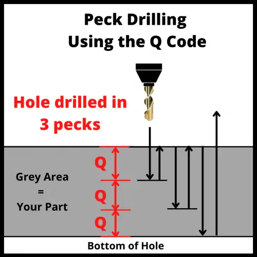
Peck drilling is a great example of how canned cycles make code easier to read and understand.

To create the code to execute the peck drilling motion shown in the picture above would require many lines of code. This would involve moving the cutter up and down repeatedly to “peck” its way down to the bottom of the hole.

With canned cycles, this can be condensed to a single line of code that contains all of the necessary information.

Learn CNC Programming – It’s Easier Than You Think!

Learning G Code doesn’t have to be difficult…

If you know what to focus on.

Join our simple, easy-to-follow course, “G Code Made Easy: CNC Programming for Beginners“. We walk you through all the important codes – with simple explanations and real-world examples.

Want to become a super-skilled CNC programmer? Join now to take the shortcut to becoming a G Code Master today!

Make Learning G Code Easy

List of canned cycles

When to use the G80 code?

The G80 code is used to turn off canned cycles.

Once you have drilled all the holes you need or threaded all the holes required, the G80 code can be used to stop drilling or threading.

If the G80 code is not used, once the machine is given a new location it will attempt to run the active canned cycle again at the new location.

The G80 code is also often used as part of a program’s safety lines to make sure that the machine is set to the correct mode.

If you needed to go back and only run a small portion of your program, it is important to know that a canned cycle wasn’t accidentally left active by the last portion of code that was run.

What other codes cancel canned cycles?

It isn’t good practice to not use the G80 command, but there are other codes that turn off active canned cycles.

G00, G01, G02 and G03 all belong to the movement group of codes and will turn off any active canned cycles.

Remember it is not good practice to turn off your canned cycles using movement codes.

Always make it clear that canned cycles have been turned off by using the G80 cancel command once you have finished running your canned cycles.

Want to learn more about CNC G Code?

G86 CNC Code Explained: An Easy Intro for Beginners [Boring with Rapid Retract]

What does a G86 code do?

The G86 command activates a boring canned cycle.

The steps the machine will take are:

  1. Rapid traverse to the R plane
  2. The machine will start boring/reaming from the R plane to the bottom of the hole (Z) at the listed feedrate (F)
  3. At the bottom of the hole, the spindle will stop and then the machine will rapid move back out of the hole.

This cycle will feed into the hole at a set feedrate but move at max speed coming back out.

The G86 canned cycle is very similar to G85 command except G85 will make the machine feed back out of the hole instead of rapid retract.

Learn CNC Programming – It’s Easier Than You Think!

Learning G Code doesn’t have to be difficult…

If you know what to focus on.

Join our simple, easy-to-follow course, “G Code Made Easy: CNC Programming for Beginners“. We walk you through all the important codes – with simple explanations and real-world examples.

Want to become a super-skilled CNC programmer? Join now to take the shortcut to becoming a G Code Master today!

Make Learning G Code Easy

What is boring?

Boring uses a single point cutting tool to create holes very accurately. This includes size, location and roundness requirements.

Boring involves creating a hole either by drilling it or some other means and then making it larger through the boring operation. Often this will require taking multiple passes to “sneak up” on the correct size requirements.

Other codes used with the G86 code

There are many different parameters used in a G86 code. They are similar to those used in other canned cycles. 

See the list below to understand all the different parts of the code.

The retracting value (R) or clearance level refers to the plane perpendicular to the Z-axis where the tool can move safely from one hole to another. 

The R value should be set so the machine will clear any and all obstacles including clamps, fixtures and the part itself.

Format for using a G86 code

G86 X2.0 Y3.0 R1.0 Z-5.0 F25.0

It would be easy to assume that the Z location is the location of the start of the hole. In reality, it is the Z location for the bottom of the boring/reaming movement.

Keep in mind that the X and Y coordinates of the hole are not usually in the same line as the G86 command.

In most programs you will see them in this format:

X2.0 Y3.0

G98 G86 R1.0 Z-5.0 F25.0

The program first identifies the coordinates of the hole and then starts the boring/reaming process.

How to cancel a G86 code

The G80 code is used to cancel the G86 boring canned cycle.

G80 is the code used to cancel all canned cycles.

If the G80 code is not used, the machine will attempt to bore a hole at each new location given in the program.

G85 vs G86

G85 and G86 are both boring canned cycles. They both move into the part at the set feedrate.

The G85 code will tell the CNC to feed back out at that same feedrate.

G86 stops the spindle and rapid retracts back out of the hole.

This means that G85 usually provides a better surface finish for the hole being machined, but takes more machining time.

R planes

The G98 and G99 codes control what position your machine will return to after finishing a canned cycle. 

The G86 code is most commonly used with the G98 code. 

Retract planes are important because they control how your machine will act when moving between locations when using canned cycles such as G86.

visualization of how a cnc machine moves using g98 and g99 codes shows motion of travel for the machine

Retract planes should be chosen so that the machine avoids any and all obstacles such as clamps, fixtures and the workpiece itself. 

Want to learn more about CNC G Code?

G85 CNC Code Explained: An Easy Intro for Beginners [Reaming]

What is a G85 CNC code?

A G85 command activates a boring and/or reaming canned cycle.

The steps the machine will take are:

  1. Rapid traverse to the R plane
  2. The machine will start boring/reaming from the R plane to the bottom of the hole (Z) at the listed feedrate (F)
  3. At the bottom of the hole, the machine will reverse directions and follow the same path back out of the hole using the same feedrate until it reaches the R plane

This cycle will feed into and out of the hole at a set feedrate. 

Using a G85 command can lead to improved part accuracy as well as better surface finish. This isn’t guaranteed though and at times it may cause these same things to get worse.

The G85 canned cycle is very similar to G81. The difference is that G81 will rapid retract out of the hole. G85 will retract at the set feedrate.

Learn CNC Programming – It’s Easier Than You Think!

Learning G Code doesn’t have to be difficult…

If you know what to focus on.

Join our simple, easy-to-follow course, “G Code Made Easy: CNC Programming for Beginners“. We walk you through all the important codes – with simple explanations and real-world examples.

Want to become a super-skilled CNC programmer? Join now to take the shortcut to becoming a G Code Master today!

Make Learning G Code Easy

Other codes used with the G85 code

There are many different parameters used in a G85 code. They are similar to those used in other canned cycles. See the list below to understand all the different parts of the code.

The retracting value (R) or clearance level refers to the plane perpendicular to the Z-axis where the tool can move safely from one hole to another.

The R value should be set so the machine will clear any and all obstacles including clamps, fixtures and the part itself.

G85 code format

G85 X2.0 Y3.0 R1.0 Z-5.0 F25.0

It would be easy to assume that the Z location is the location of the start of the hole. In reality, it is the Z location for the bottom of the boring/reaming movement.

Keep in mind that the X and Y coordinates of the hole are not usually in the same line as the G85 command.

In most programs you will see them in this format:

X2.0 Y3.0

G98 G85 R1.0 Z-5.0 F25.0

The program first identifies the coordinates of the hole and then starts the boring/reaming process.

How to cancel a G85 code?

The G80 code is used to cancel the G85 boring/reaming canned cycle. G80 is the code used to cancel all canned cycles.

If the G80 code is not used, the machine will attempt to bore/ream a hole at each new location given in the program.

When to use a G85 code?

The G85 code is useful in programs when a hole needs to be enlarged, a hole needs to be tapered (create an inner cone shape), or when a hole needs a high-quality finish to improve accuracy.

You need to understand that although reaming and boring are operated with the same command and tool (the reamer tool), they are not the same operation. 

Reaming is just for finishing, while boring is used to change the shape of a hole by enlarging it or tapering it.

When not to use a G85 code?

The G85 command should never be used for drilling a hole because it can damage the cutting tool, the workpiece, and the operator. 

A G85 code should be used on a hole which has already been drilled.

G98 and G99 when using a G85 code

visualization of how a cnc machine moves using g98 and g99 codes shows motion of travel for the machine

Before applying the G85 code, the reamer tool should move first to a safe position above the reference (R) plane.

With most canned cycles it is best that the tool moves to a starting point first and then to a reference plane with either the G98 or G99 command.

When using the G98 code, at the end of the cycle the tool will go back to the starting point (above the R plane) in rapid movement after passing the reference plane.

When using the G99 code, at the end of the cycle the tool will only return to the reference plane after finishing the boring/reaming cycle.

What to think about when using a G85 code?

Hole size

The holes where the G85 cycle will be run should be drilled close to the final diameter size to ensure a good surface finish and increase the life of your cutting tool.

Speeds and feeds

The material to be machined and the required surface finish/roughness should be used to determine the appropriate speeds and feeds to use when machining.

Retract planes

There are two G codes which control how the machine will retract when using canned cycles such as G85.

The G85 code is most commonly used with the G98 code

Retract planes are important because they control how your machine will act when moving between locations when using canned cycles such as G85.

Retract planes should be chosen so that the machine avoids any and all obstacles such as clamps, fixtures and the workpiece itself. More info about the type of retract planes that can be used is shown below.

Canned cycles that are similar to G85

G85 vs G81

The G85 and G81 canned cycles are very similar. The difference between the two is that the G81 cycle will retract out of the hole at the machines rapid speed.

G85 will retract out of the hole at the same feedrate that it fed into the hole.

G85 vs G86

The G86 canned cycle is used for boring and is similar to G85 except that it stops the spindle before retracting the tool. The spindle is restarted when it reaches the retract (R) plane.

Because the spindle stops when using G86, the cutting tool can leave a mark on the surface of the hole. For this reason, G86 is mainly used with roughing operations.

All three commands (G81, G85, and G86) are canceled with the G80 code.  

Want to learn more about CNC G Code?

G84 CNC Code Explained: An Easy Intro for Beginners [Tapping]

What is a G84 CNC code?

A G84 command activates the tapping canned cycle.

Tapping is threading the female portion of a mating pair. Basically, this means you are creating the thing that will be screwed into.

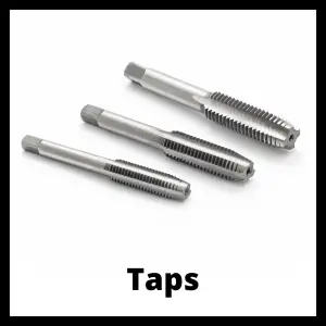
three different taps used for creating internal threads with a CNC machine

Tapping is done by rotating the spindle, which holds the tap, down through the hole until it reaches the desired depth (bottom of the hole).

Once at the bottom of the hole, the spindle will change directions and reverse out of the hole.

The G84 code is also used for peck tapping.

Peck tapping is similar to peck drilling where the machine will tap in steps. 

illustration that shows the difference between peck drilling and standard drilling in a CNC machine

For instance, if your peck depth was 0.1” then the machine would feed down 0.1” and then back up. Then the machine would feed down to 0.2” and back up. Rinse and repeat going 0.1” lower with each peck.

Learn CNC Programming – It’s Easier Than You Think!

Learning G Code doesn’t have to be difficult…

If you know what to focus on.

Join our simple, easy-to-follow course, “G Code Made Easy: CNC Programming for Beginners“. We walk you through all the important codes – with simple explanations and real-world examples.

Want to become a super-skilled CNC programmer? Join now to take the shortcut to becoming a G Code Master today!

Make Learning G Code Easy

When to use a G84 code?

The G84 code is used when you want to tap (thread) an existing hole in a part.

Never use the G84 command to drill a hole.

This operation is only meant to remove the material that will form the threads of the holes, not create the hole as well.

Other codes used with the G84 code

When using a G84 code you need to consider all the aspects that control the tapping process, these are:

The retracting value (R) or clearance level refers to the plane perpendicular to the Z-axis where the tool can move safely from one hole to another.

The R value should be set so the machine will clear any and all obstacles including clamps, fixtures and the part itself.

G84 code format

The format for using a G84 command is shown below:

G98 (or G99) G84 X2.0 Y3.0 R1.0 Z-5.0 F25.0

It would be easy to assume that the Z location is the location of the start of the hole. In reality, it is the Z location for the bottom of the hole tapping movement.

Keep in mind that the X and Y coordinates of the hole are not usually in the same line as the G84 command.

In most programs you will see them in this format:

X2.0 Y3.0

G98 G84 R1.0 Z-5.0 F25.0

The program first identifies the coordinates of the hole and then starts the tapping process.

How to cancel a G84 code?

The G84 code is canceled with the G80 command.  

If the G84 code is not canceled, the machine will try to tap a hole at every new location given in the program.

The G80 command cancels all canned cycles.

What to think about when using a G84 code?

Retract planes

visualization of how a cnc machine moves using g98 and g99 codes shows motion of travel for the machine

The G84 command is usually followed by G98 in the same line of code, in which case the machine will use the Z coordinate (height of the first hole) to move between holes. Keeping in mind this aspect can prevent redundant coding and machining errors.

When tapping it is advisable to set your R plane higher than usual.

CNC machines are capable of switching between modes very quickly, but the change is not instantaneous. 

The higher R plane gives the machine time to stabilize and ensure it is working at the correct feedrate before starting the cut.

Speeds and feeds

You will need to set the spindle speed before using the G84 cycle. 

When using G84, the spindle should always be moving clockwise through the use of an M03 command.

The feed rate of code G84 will be the pitch of your thread.

Various holds or overrides for speeds and feeds will not work when tapping. This is for safety purposes.

Hole size and location

Before using the G84 there must be a previous drilling cycle.

The correct hole diameter for a tapping operation will be the final diameter of the screw minus the pitch. For example, the diameter of the hole for an M10 x 1.5 mm hole will be 8.5 mm.

Keep in mind that the X and Y coordinates of the hole are not usually in the same line as the G84 command. The standard format for selecting your hole location and calling the G84 tapping cycle is shown below:

X50.0 Y50.0

G84 Z-40.0 R5.0 F20

The machine is moved to the location of the hole to be threaded and then the hole cycle is used.

G84 rigid tapping

Rigid tapping means that the tap can remain rigid throughout the cycle. The machine spindle locks in with the feedrate similar to the screw cutting process.

There are tapping heads specially designed for this process.

To perform Rigid Tapping, the machine should be able to synchronize feed motion and spindle speed. 

This option may not be available on all machines, especially older ones.

Check your machine manual to make sure you are capable of rigid tapping.

However, Rigid Tapping mode can cause issues due to chips sticking to the tool or increased cutting resistance. That’s why it is important to consider peck tapping.

G84 peck tapping

Including the Q code in the G84 command line will immediately set the machine to a peck tapping cycle.

This means that the spindle will rotate to a specified depth (Q value) in each tapping peck and then repeat the process, one step or “peck” at a time until reaching the bottom of the hole.

Peck tapping allows chips to exit the hole, making the tapping process easier and safer. 

The downfall of peck tapping is that it increases machining time when compared to standard tapping.  

The picture below is for drilling but it is the same concept. The pecks do not need to come all the way back up either.

You can drill down 0.200″ and then retract 0.100″ and then repeat the process going down 0.100″ at a time.

illustration that shows the difference between peck drilling and standard drilling in a CNC machine

G84 vs G74

The G74 cycle is the left-hand tapping cycle, sometimes called the reverse tapping cycle.

It performs the same operation as the G84 command but with the difference that the spindle rotates counterclockwise instead of clockwise.

The G74 left hand tapping cycle creates left hand internal threads while the G84 canned cycle creates standard or right-hand internal threads. Left hand threads are the opposite of your standard threads.

If G84 creates threads that are lefty-loosey, righty tighty then G74 creates threads that are righty-loosey, lefty tighty. In other words, G74 creates threads that would be screwed in the opposite way of normal.

The G74 command also has the ability to peck tap.

Both the G74 and G84 commands are modal commands which means they will stay on and in effect until they are either changed or canceled.

The cancel command to use with both cycles is the G80 code.

Want to learn more about CNC G Code?

G83 CNC Code Explained: An Easy Intro for Beginners [Peck Drilling]

What is a G83 CNC code?

G83 is a modal command that sets the CNC machine to run a peck drilling cycle.

The practice of peck drilling refers to drilling a hole in a series of steps (pecks) instead of drilling the complete depth of the hole in a single pass.

Differences between peck drilling and standard drilling

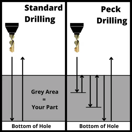
The main difference between peck and standard drilling is that the peck drilling process removes the material in multiple steps, while standard drilling is a one-step process.

Both commands are intended to make holes, but the peck drilling cycle allows more control over how the hole is drilled.

illustration that shows the difference between peck drilling and standard drilling in a CNC machine

Peck drilling is the first option for CNC programmers when making blind holes. The pecking process helps break chips as well as remove them and any other debris from the hole during the drilling process.

Trouble removing chips from the hole when drilling can cause size and/or surface finish issues.

Standard drilling is far more common when dealing with simple through (thru) holes.

Learn CNC Programming – It’s Easier Than You Think!

Learning G Code doesn’t have to be difficult…

If you know what to focus on.

Join our simple, easy-to-follow course, “G Code Made Easy: CNC Programming for Beginners“. We walk you through all the important codes – with simple explanations and real-world examples.

Want to become a super-skilled CNC programmer? Join now to take the shortcut to becoming a G Code Master today!

Make Learning G Code Easy

Other codes used with the G83 code

The feed rate (F) is dependent on the material that is being cut and the diameter of the drilling tool that you are using.

The retracting value (R) or clearance level refers to the plane perpendicular to the Z-axis where the tool can move safely from one hole to another.

Also, some machines might use L instead of K for cycle repetition (depending on the model and machine type). If you are the programmer, remember to check the machine’s manual for further details.

G83 code format

The format for using a G83 command is shown below:

G98 (or G99) G83 X2.0 Y3.0 R1.0 Z-5.0 Q1.0 F25.0

It would be easy to assume that the Z location is the location of the start of the hole. In reality, it is the Z location for the bottom of the hole drilling movement.

Keep in mind that the X and Y coordinates of the hole are not usually in the same line as the G81 command.

In most programs you will see the G83 code in this format:

X2.0 Y3.0

G98 G83 R1.0 Z-5.0 Q1.0 F25.0

The program first identifies the coordinates of the hole and then starts the drilling process.

When to use a G83 code?

When you need to drill deep holes in a workpiece, that would need more than one step to avoid jamming or tool breakage.

G83 is especially useful for drilling blind holes when you want to achieve a clean finish.

When not to use a G83 code?

If you want to make a shallow hole, you won’t probably need the G83 code.

There is no need for the tool to take on several pecks if the depth of the hole is less than an inch (depending on the material and tool).

The G83 command works best when you follow a general rule: if the depth of the hole is 3 to 4 times greater than its diameter, use G83. 

What to think about when using a G83 code?

Peck depth

The peck depth is set using the Q code.

The bigger the depth of peck is, the faster the drilling operation will be. So, in this sense, choosing an appropriate peck distance can speed up machining time.

Usually, when using G83, the maximum peck distance recommended will be equal to the hole’s diameter

However, you must be careful with hard materials and heavy chips that can come out of the hole during the process. 

Some CNC models have variable-depth peck controllers, and you could play with them to decrease peck distance in each pass by taking a big peck in the first step and then taking shorter ones to avoid plugging up the tool.

Be sure to check the machine’s manual first to see the available options for controllers.

Retract planes

The retract plane is the location that the machine will return to after each canned cycle.

There are two codes that affect retract planes.

The G98 code will cause the machine to return to the Z location at the start of the canned cycle.

The G99 code will tell it to return to the R plane.

visualization of how a cnc machine moves using g98 and g99 codes shows motion of travel for the machine

Selecting a retract plane that is above any potential obstacles in the machine such as fixtures, clamps, or the part itself will allow the machine to safely move between each hole drilling location.

If the R plane is too low it could cause damage on the workpiece and lead to disaster. However, if an R plane is too high above the workpiece’s surface, it could increase machining time, due to the extra time needed to go all the way up to the R value after each drilling. 

Positioning mode

When using the G83 drilling cycle, you will need to be aware of the positioning mode that is currently active.

If the G90 code (absolute positioning) is active, the machine will read all locations as relative to a single zero location.

If the G91 code (incremental positioning) is active, the machine will read all locations as relative to its current position.

Pay careful attention to your current positioning mode because using the wrong one can easily result in a machine crash.

graph paper example of absolute positioning with multiple points as examples
graph paper example of incremental positioning with multiple points as examples

The difference between the two modes is shown above. 

When in absolute mode, the machine will move relative to a fixed zero location.

When in incremental mode, the machine will move relative its current location.

Look at the first move in the pictures above. They both start at (0,0). They both move up one block in the Y axis.

On the second move, in absolute mode the machine the machine is still reading the new location as from the fixed zero location. 

In incremental mode the move is from the machines current location which is why the move is 1 block shorter in the Y axis.

How to cancel a G83 code?

The G80 command is used to cancel a G83 code as well as all other canned cycles.

If the G83 command is not canceled, then the machine will continue to drill holes in every location given in the program.

G83 vs G73

The most similar code to G83 is G73.

They are both peck drilling cycles with one key difference

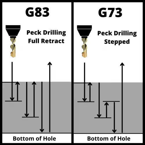
G83 will retract completely out of the hole after each peck to the retract plane. 

G73 will only retract to the start of each peck.

The G73 canned cycle is a peck drilling cycle but with a shorter retract intended for relatively shallow holes. Meanwhile, the G83 command is peck drilling with a full retract intended for deep holes.

an illustration that shows the difference between the G73 and G83 CNC codes

Both commands are meant to help break and clear chips. G83 does a better job of this by fully retracting out of the hole but with the added expense of a longer cycle time.

On the other hand, G73 is designed to break up stringy chips, while G83 is intended to pull chips up and out of deep holes.

G83 vs similar codes

Besides G73 there are a few other G-codes for drilling holes with slight variations in the drilling process which make them better to use in certain circumstances.

Code

Name

Function

Drill simple, shallow holes and center drilling

Standard drilling cycle with a dwell at the bottom of the hole

Drill into the part in steps (pecks) and after each peck, fully retract from the hole

Similar to G83, but instead of retracting completely out of the hole, the machine will pull back a specified amount and then resume drilling

Want to learn more about CNC G Code?

G82 CNC Code Explained: An Easy Intro for Beginners [Drill with Dwell]

What does a G82 code do?

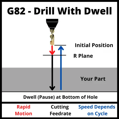
The G82 code is for a standard drilling cycle with a dwell at the bottom of the hole.

The machine will drill the hole in one straight shot, stop for a set amount of time at the bottom of the hole and then retract out of the hole.

G82 is a modal command and just like other modal codes you will need to deactivate it by calling another G code of the same type (canned cycle in this case) or by using the G80 canned cycle cancel command to stop drilling.

G82 Code Illustration

Learn CNC Programming – It’s Easier Than You Think!

Learning G Code doesn’t have to be difficult…

If you know what to focus on.

Join our simple, easy-to-follow course, “G Code Made Easy: CNC Programming for Beginners“. We walk you through all the important codes – with simple explanations and real-world examples.

Want to become a super-skilled CNC programmer? Join now to take the shortcut to becoming a G Code Master today!

Make Learning G Code Easy

When to use a G82 code?

The G82 command is useful when you want to drill holes that are not too deep and can be drilled in just one step.

It is used most often when the hole being drilled needs a better surface finish at the bottom of the hole.

The G82 canned cycle does not include any retract steps (pecks) when drilling.

For this reason, if you want to drill a deep hole, the best option would be to use the G83 peck drilling deep hole canned cycle. Peck drilling will help clear chips.

illustration that shows the difference between peck drilling and standard drilling in a CNC machine

Other codes used with the G82 code

G82 code format

The format for using a G82 command is shown below:

G82 X2.0 Y3.0 R1.0 Z-5.0 P500 F25.0 G98

It would be easy to assume that the Z location is the location of the start of the hole. In reality, it is the Z location for the bottom of the hole drilling movement.

Keep in mind that the X and Y coordinates of the hole are not usually in the same line as the G82 command.

In most programs you will see them in this format:

X2.0 Y3.0

G98 G82 R1.0 Z-5.0 P 500 F25.0

The program first identifies the coordinates of the hole and then starts the drilling process.

What to think about when using a G82 code?

Retract planes

The retract plane is the location that the machine will return to after each canned cycle.

There are two codes that affect retract planes.

The G98 code will cause the machine to return to the Z location at the start of the canned cycle.

The G99 code will tell it to return to the R plane.

visualization of how a cnc machine moves using g98 and g99 codes shows motion of travel for the machine

Selecting a retract plane that is above any potential obstacles in the machine such as fixtures, clamps, or the part itself will allow the machine to safely move between each hole drilling location.

If the R plane is too low it could cause damage on the workpiece and lead to disaster. However, if an R plane is too high above the workpiece’s surface, it could increase machining time, due to the extra time needed to go all the way up to the R value after each drilling. 

Positioning mode

When using the G82 canned cycle, you will need to be aware of the positioning mode that is currently active.

If the G90 code is active, the machine will read all locations as relative to a single zero location.

If the G91 code is active, the machine will read all locations as relative to its current position.

Pay careful attention to your current positioning mode because using the wrong one can easily result in a machine crash.

graph paper example of absolute positioning with multiple points as examples
graph paper example of incremental positioning with multiple points as examples

How to cancel a G82 code?

The G80 command is used to cancel a G82 code as well as all other canned cycles.

If the G82 command is not canceled, then the machine will continue to drill holes at every location given in the program.

G82 vs Similar Canned cycles

The G82 command is one of the simplest drilling canned cycles.

Besides G82 there are a few other G-codes for drilling holes with slight variations in the drilling process which make them better to use in certain circumstances.

Code

Name

Function

Drill simple, shallow holes and center drilling

Standard drilling cycle with a dwell at the bottom of the hole

Drill into the part in steps (pecks) and after each peck, fully retract from the hole

Similar to G83, but instead of retracting completely out of the hole, the machine will pull back a specified amount and then resume drilling

Want to learn more about CNC G Code?