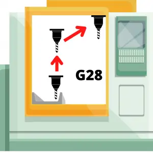
7 Best Micrometers For Any Budget

Micrometers are amazingly accurate measuring tools. 

But for anyone just starting out it can be hard to know which ones are good and which ones are bad.

This has only gotten trickier in recent years as some of the once great manufacturers have moved their production to China and various other countries known for lesser quality. On top of that some of the Chinese manufacturers have really upped their game and are producing quality tools.

We’ll break it down for you and let you know which micrometers are best with some tips on what to avoid.

One last tip if you are very new to micrometers.

Think about what you plan to measure. What are the sizes involved? Most of the time people don’t need huge sets of micrometers.

My advice for someone new would be to get the best set of 0-1” micrometers that they can afford. This is the tool that will get the most use.

A good starting point is a quality 0-1” mic from a company like Starrett (analog) or Mitutoyo (digital).

If you are looking to measure over a larger measuring range then see our post on the best micrometer sets.

Now let’s break down our picks for the best micrometers.

Factors we consider when reviewing micrometers

Accuracy

Know your tolerances!

A common mistake the newbies make is thinking they need a micrometer when a caliper will do the job just fine.

mitutoyo digital caliper measuring 1 inch block
0-6″ Mitutoyo digital caliper

If your tolerances are +/- .001” or more then you can likely get by with a dial or digital caliper. These can be had for prices well below the cost of a good micrometer.

Another benefit is that calipers are much more versatile and have larger measuring ranges.

For more info check out our Micrometers vs Calipers post to see what makes these tools different.

Digital vs analog micrometers

Digital micrometers are a good choice because they are quick to read. This is especially helpful for anyone just starting out. 

It’s not that hard to read an analog micrometer but some people struggle a little learning to read a micrometer. For a little help learning to read a standard analog micrometer, see our post that walks you through the process – How to Read a Micrometer

Digital mics simplifies the process of reading your mic, but it is still a good idea to learn how to read a standard analog micrometer.

Digital micrometers also have the added benefit that they can be easier to see the readings. If your vision isn’t great up close or you need a new set of readers, you might want to stick with a digital micrometer.

Analog micrometers have the benefit of always being ready to use. Digital mics require a battery and some are better than others when it comes to battery life.

An analog mic will always be ready to pick up and use. If you only use your digital micrometer occasionally then it might be a good idea to take the battery out when not in use. This way it isn’t dead when you need to use it.

button cell battery for micrometer
Typical button cell battery used in digital micrometers

Measurement units

Unless you are purchasing a digital micrometer, you will only get a reading in one set of units. Take note of the units you will be working with and buy accordingly. 

This seems pretty self explanatory. I include it only as a reminder to double check your units before purchasing and to contemplate getting a digital micrometer if you are going to be working in both units constantly.

Measuring range

Micrometers typically are capable of taking measurements over a one inch measuring range. You will find them available individually, such as a micrometer that can take measurements from 4″-5″ and you can also find them sold as sets.

anytime tools micrometer set
0-6″ micrometer set

Set sizes are generally sold in 0-3″, 0-6″ and 0-12″ varieties. They are available in many different configurations but these sets are the most common. Sets will usually start at 0″ and go up. Some of the bigger sets differ and only include larger size micrometers such as with a 12″-18″ set. 

As the set gets bigger and the micrometers get larger, the cost gets significantly higher. 

Because this is the case, don’t go out and buy a set that contains tools you won’t be using. In many instances a 0-3″ micrometer set will be sufficient for taking the majority of your measurements. 

Think about the sizes you will need to measure and don’t overspend on a set larger than you really need.

Calibration certificates

Does your micrometer need to be calibrated?

Yes, but also no.

What you will want to do is check the calibration yourself. Use a known standard such as a set of gage blocks to verify the accuracy of the tool over its measuring range. At a minimum, verify the micrometer with the standard provided by the manufacturer.

What you should not do is pay extra to get a calibration certificate from the micrometer seller. Many sellers will offer a NIST traceable calibration certificate at a substantial upcharge. In reality, all the calibration certificate tells you is that the tool was found to be accurate at the time of calibration. 

box damaged in shipping
Damaged shipping box

In between the time you receive it and the time the calibration was performed, the tool passed through many hands, most notably the hands of a shipping company. I shouldn’t need to tell you that those shipping companies are not always gentle in the transportation of your precision measuring instrument.

It will probably be packaged well and everything will be fine. Remember many micrometers have withstood harsh machine shop environments for decades and continued to measure as accurately as a brand new tool. 

Should you buy a used micrometer?

Used tools are an excellent way to save money when it comes to micrometers. This is even more true when talking about depth micrometers, if you can find the right deal.

Generally, I have found prices for used tools fall into two categories; cheap and priced like new. Avoid the like new prices. It just isn’t worth it. Some people just want way to much for their tools.

Personally, I wouldn’t be too excited about a standard used outside micrometer unless it was pristine and from a brand like Starrett or Mitutoyo.

There are plenty of other brands out there that put out quality tools for years. The tricky thing is that over the years some of these manufacturers have taken a step down in quality. Case in point, Fowler and Browne & Sharpe. The older stuff is much better.

If you’re looking to pick up some good tools on a budget, then keep an eye on Facebook marketplace and Craigslist along with hitting up some local yard sales. I’m sure it depends on your area, but yard sales have always been where I find the best deals.

igaging digital micrometer in case
Micrometer with a case

A good tip when looking for used tools is to look for ones that still have the original case or box. It is usually a sign that they were well cared for.

For more info about used micrometers, see our post about the best micrometer brands to find out which ones stand the test of time and the brands you should avoid.

Carbide vs non-carbide tipped micrometers

Stainless steel tips
Carbide tips

Carbide tips have the benefit of increased resistance to wear. The downfall is that they are more prone to chipping of the anvil face.

If you are careful with either type, it is unlikely that wear or chipped anvils will be an issue.

Micrometer cases

A good case will go a long ways towards keeping your tool protected and safe. Whether you’re working in a machine shop or using it in your garage, there are hazards everywhere. Coolant isn’t something you want on most precision tools. The same can be said of dirt and brake dust.

Give them a good wipe down after use and keep them safely in a case or toolbox to make sure they will be in working order for years to come.

Micrometer ratchets

Friction thimble stop
closeup of a micrometer with the ratchet stop identified
Click ratchet stop

A good ratchet makes a big difference when it comes to micrometers. If the ratcheting mechanism is bad, then the tool could give bad readings.

Micrometer ratchet mechanisms come in many forms. The most common types are the click style ratchet and the friction thimble.

Personally, I prefer to use the click style or no ratchet over the friction thimble. Just a matter of personal preference. 

Some companies claim that the friction thimble, which simply spins freely once it is at the correct size, is more accurate but I have never known this to be the case.

If possible, try out both the click style ratchet and the friction thimble and determine what you prefer. If this isn’t possible, I recommend starting with a click style ratchet for your micrometer.

IP ratings

If you go with a digital micrometer, pay attention to the IP rating of the tool. The tables below show how well protected the device is from the elements.

The first number is for protection from solids such as chips and dust. The second number is for protection from liquids such as oil and coolant.

Both of the Mitutoyo digital micrometers recommended above are rated IP65. This is a very high level of protection. The next level down that is commonly seen is a IP54 rating which would be sufficient for most environments as well. 

ingress protection (IP) ratings solids description
ingress protection (IP) ratings liquid protection

Data transfer

Many micrometers are capable of transferring measurement data to a computer. I don’t believe this is something that will prove useful for most users unless they are working in a high volume industrial setting so I will be brief on the topic. 

Please note that there are multiple ways of transferring measurements to a computer including:

  • USB
  • SPC
  • RS232
  • Wireless, including Bluetooth
  • Other proprietary wired and wireless formats

If data transfer is a feature you are interested in then please pay attention to the manner in which the tools communicates and the price of any required accessories. The cost of a simple cable can often be half the cost of the micrometer itself or more.

Best overall micrometer

Best overall micrometer
We earn a commission if you make a purchase, at no additional cost to you.

Mitutoyo 293-180-30 QuantuMike

The best overall micrometer is easily the QuantuMike by Mitutoyo.

Mitutoyo has long been one of the very best micrometer manufacturers. They make top of the line tools across the board. Standard micrometers, digital mics, depth mics. You name it and they are leading the pack.

Every micrometer on our best of list is incredibly accurate but the digital micrometers from Mitutoyo, including this one, are on another level. With accuracy of .00005” or .001mm, Mitutoyo’s digital micrometers measure tolerances 2x tighter than most standard micrometers.

For reference, the human hair is about .003”. Take a strand of your hair and split it into 60 pieces and that is how accurate these micrometers are.

Besides the accuracy, the other standout feature of the QuantuMike is the speed. Anyone who has used a micrometer knows they aren’t quick to open or close.

The QuantuMike is unlike any other micrometer on the market and opens and closes four times faster. Each turn of the thimble moves the tool .100” instead of the normal .025”. No arm rolling needed.

Combining speed and accuracy is not a feat easily accomplished but Mitutoyo’s QuantuMike has done just that and more.

For a more in depth look at what makes the QuantuMike so special, see our full review.

Best digital micrometer

Mitutoyo 293-340-30 Digital Micrometer

I am a huge fan of Mitutoyo’s digital micrometer line. Across the board they are quality all around.

Rather than gush over the quality of these things for paragraphs on end. I am just going to include a bulleted list of what makes them so good:

  • Extremely accurate
  • Quick to use and take measurements
  • Battery life is long
  • IP65 rating means they are protected from dust and splashing water
  • Great build
  • Excellent durability

If the price is too high, I would recommend going with a standard analog micrometer instead. If you must get digital, then go with one from one of the bigger budget brands such as iGaging.

mitutoyo digital micrometer

Unlike standard analog micrometers, the cheap ones are not as close in quality to the budget tools. A budget digital micrometer is going to be a significant step down. That doesn’t mean it’s bad. It just means that the gap is bigger.

If you are still on the fence, re-read the bulleted list and contemplate whether its better to “buy once, cry once” or not.

Best budget micrometer

Best budget micrometer
We earn a commission if you make a purchase, at no additional cost to you.

Anytime Tools 0-1″ Micrometer

There was a time where Chinese made knockoff micrometers were bad. I mean real bad. This isn’t the norm anymore though.

Many manufacturers such as Anytime Tools have made a name for themselves by providing quality measuring instruments at a fraction of the price of higher end tools.

For instance, a 0-6” set of micrometers can be had for about the same price as a single 0-1” Starrett micrometer. That’s a pretty huge price variation.

And quality wise there just isn’t a big difference between the cheaper tools and the more expensive ones anymore. At least when it comes to the best of the budget tools. If the pricier tools from companies like Starrett or Mitutoyo are 5% better, honestly most won’t notice the difference.

One note about budget priced micrometers, don’t go buy some random mic made in China and expect it to have the same quality. The good brands that are cheaper are usually American companies that are purchasing the tools from Chinese manufacturers. They have performed the quality control to ensure you get a good product.

If you want a quality tool that is accurate and built to last but your budget doesn’t allow for the best from Starrett or Mitutoyo check out Anytime Tools.


Best standard micrometer

Starrett T436.1 0-1″ Micrometer.

For standard analog micrometers, Starrett has put out a line of excellent measuring tools for a very long time. Founded in 1880, they were one of the creators of the modern micrometer and it shows.

Having never used a micrometer from the 1800s, I can not attest to their quality from 100 years ago. What I do know is that anything made on this side of the 1950s has been excellent. In machine shops all over the world, Starrett micrometers bought decades ago are still in use.

They are built to last. Often the only tell-tale sign of their age is a slight polishing of the frame or thimble from heavy use.

The quality does come at a price though. If you won’t be using this tool all day every day or for an extremely critical measurement, it might be best to think about our best budget micrometer below. If you are going to put this tool to use constantly, you would be hard pressed to find a better tool.

Best depth micrometer

Depth micrometers are another monster. Certainly more difficult to manufacture, as a result they are quite a bit higher in price.

Because they are so expensive, I am going list a few different options.

As a side note, when it comes to depth mics think about looking for used options. Many people take excellent care of their tools and you can save a pretty penny by picking up a second hand set. My only recommendation would be to find a way to verify them before buying. Bringing a set of gage blocks along could save you quite a bit of headache in the future.

Best digital depth micrometer

Best digital depth micrometer
We earn a commission if you make a purchase, at no additional cost to you.

Mitutoyo 329-350-30 Digital Depth Micrometer

Just like their outside micrometers, the digital depth mics from Mitutoyo are excellent.

They are easy to use and easy to read. Most importantly, they are extremely accurate. Unlike normal micrometers, depth mics are one tool that the Chinese knock offs have really struggled to replicate. Many times cheaper depth mics are not accurate. The quality simply isn’t there.

This is not the case with Mitutoyo depth mics.

Mitutoyo depth mics, like their other digital micrometers, are in a league of their own. Unfortunately, their cost reflects this.

These depth mics are the best of the best but I only recommend them if you plan to put them to heavy use. If not, look into one of the non-digital options below to save more than a few bucks.

Best standard depth micrometer

Starrett 440Z-6L 0-6″ Depth Micrometer

Both Starrett and Mitutoyo make great depth micrometers of the non-digital variety. Both companies make depth mics that are strikingly similar to their standard outside micrometers.

Really the differences are minor. Both are highly accurate. The ratchet on the Starrett is a little better. Additionally, the base is slightly smaller which I prefer.

The Mitutoyo depth micrometers have two types of bases. One that is larger such as what is seen on the digital version above. The other type is smaller. This makes it slightly more tipsy. The base of the Starrett depth mic feels like it is just right, smack in the middle.

It really is only small differences that give the Starrett depth micrometer the edge. You can’t go wrong with either, especially if you can find a good deal on it somewhere or pick one up used for a good price.

Best budget depth micrometer

Best budget depth micrometer
We earn a commission if you make a purchase, at no additional cost to you.

Fowler 52-225-116-0 0-6″ Depth Micrometer

I’m sure you have noticed that the prices are pretty high on all of the listed depth mics so far.

This is because the quality and accuracy don’t come cheap with depth micrometers. This depth mic from Fowler is the about the closest thing you will find to cheap and accurate.

I don’t know about all of their tools but many of Fowler’s gauges seem to be made in China. Nothing wrong with that in particular as seen with some of our other mic recommendations. Unfortunately, Chinese made depth mics are not something that they have perfected.

I have used Fowler depth mics that are every bit as accurate as Starrett or Mitutoyo, I just wouldn’t count on every single one coming off the line that good.

The nice thing about many online retailers is that they have good return policies. So if you absolutely need a depth mic and need it as cheap as possible then order away. Just make sure you check it for accuracy when you get it and send it packing if it isn’t up to snuff.

Related articles

For more information check out these related articles:

G49 CNC Code Explained: An Easy Intro for Beginners [Tool Length Compensation Cancel]

What does a G49 code do?

The G49 code cancels tool length compensation.

Once the G49 command is used, the machine will not account for any tool length (H) offsets in its movement.

This means the machine will move the end of the spindle to all new locations.

When tool length compensation is in effect by using either a G43 or G44 code, the machine will move the end of the cutting tool to all new locations.

an illustration of a cnc machine that shows how a g43 code offsets the program

What is tool length compensation?

Tool length compensation is your CNC machine accounting for the length of the cutting tool when running the program.

It does this by adjusting for the cutter by a value that is entered into the offset library. This offset is called an H offset.

mach 3 tool offset table
A tool offset library

H offsets are assigned by using the H code with a G43 code to turn tool length compensation on. 

For example, the line

G43 H02 

tells the CNC to turn tool length compensation on using the #2 height (H) offset.

illustration of a cnc cutting tool that shows what an H offset is

Learn CNC Programming – It’s Easier Than You Think!

Learning G Code doesn’t have to be difficult…

If you know what to focus on.

Join our simple, easy-to-follow course, “G Code Made Easy: CNC Programming for Beginners“. We walk you through all the important codes – with simple explanations and real-world examples.

Want to become a super-skilled CNC programmer? Join now to take the shortcut to becoming a G Code Master today!

Make Learning G Code Easy

Where will you find G49 in a CNC program?

The G49 code is not a required part of your CNC program.

It is rare that you would want to move the tip of your spindle to an exact location. You will almost always have a cutting tool in the spindle that you will want to account for.

This means the G49 code is not used often. It is more important to make sure you have the correct tool and offset selected.

Some programmers choose to include the G49 code as part of their safety block of code.

Others skip it and just make sure to call out the correct offset for their tool at the start of a new section of code.

As long as you switch to the correct offset for the currently loaded tool, then there is no need to cancel tool length compensation with the G49 code.

What to think about when using a G49 code?

Different machines can interpret the G49 code in varying ways.

When the G49 code is used, some machines will immediately move the end of the spindle to the location the end of the cutting tool was previously in.

If you aren’t in a safe location with enough clearance, the machine could crash. That’s never good!

If you plan to use a G49 code then make sure you understand how your CNC will react. Check your manual!

Other CNC cancel commands

Code

Name

G40

Cancel Cutter Compensation

G49

Cancel Tool Length Compensation

G50

Cancel Scaling

G67

Cancel Custom Macro Call

G69

Cancel Rotation

G80

Cancel Canned Cycles

Codes that are similar to G49

There are multiple commands that will cause the machine to act very similar to when a G49 codes is used.

Using the M30 code, the reset command or an H0 offset will cause the CNC machine to cancel tool length compensation.

Want to learn more about G Code for your CNC?

G54-G59 CNC Codes Explained: An Easy Intro for Beginners [Work Offsets]

What does a G54 code do?

The G54 command tells the CNC machine where your part is located.

To put it differently, the G54 code sets the work offset zero location to be used currently in your CNC program.

On most CNC machines, the G54 through G59 codes are for selecting these work offsets or work coordinate systems. G54 is the first code in this group and the most frequently used work offset G code.

These work offset codes (G54-G59) are each matched to coordinate locations which have been set in the CNC machine’s offset library.

CNC program zero list showing XYZ coordinate locations
Work offset locations

Selecting a work offset code tells the CNC machine which work coordinate system to use. The coordinate locations tell the machine where the zero location is. This is the location where the X, Y, and/or Z coordinate values = zero.

G54 is a modal command

Once the G54 work offset code is used, all sizes and locations in the program will be relative to the zero location of the part until the offset is switched to a different work offset code such as G55 or G56.

This type of G code is called a modal command.

Modal commands remain in effect until they are canceled. This is true even if you restart your program.

Until you cancel the command or change it, the modal command G54 will stay in effect.

Obviously, this can cause trouble if you aren’t paying attention.

For this reason, most CNC programs will be created with start-up or safety commands. The safety commands make sure that the machine is always in the correct modes and this includes having the correct work offset chosen.

Learn CNC Programming – It’s Easier Than You Think!

Learning G Code doesn’t have to be difficult…

If you know what to focus on.

Join our simple, easy-to-follow course, “G Code Made Easy: CNC Programming for Beginners“. We walk you through all the important codes – with simple explanations and real-world examples.

Want to become a super-skilled CNC programmer? Join now to take the shortcut to becoming a G Code Master today!

Make Learning G Code Easy

G54 vs G55-G59

All of the CNC codes from G54 to G59 act the same. They are all work offsets.

Everything in this article that applies to the G54 command also applies to all of the other work offsets including G55-G59.

Work offsets work like presets on your radio, except you store a location instead of a radio frequency. You can then call it up quickly and switch between them as needed.

This makes operations such as referencing different sides of a part or machining multiple parts at once easier.

two work offsets being used on the same part
Two work offsets being used to drill holes on a single part

Each of these commands is modal so they will stay on until turned off or changed.

The picture below shows how multiple work offsets can be set in a CNC and how they compare to the machine zero location.

visual to show cnc work offsets G54-G59 with the zero locations shown

When to use a G54 code

A G54 code can be found at any point within the program but the most likely location is at the start of the program or at the start of a new section of code.

Example time!

Imagine you have a part that you want to drill holes in and then counterbore the same holes.

counterbore on metal part
A hole with a counterbore

In the program there will be a section of code for drilling the holes and a section of code for counterboring them.

Even though those operations both use the G54 offset, the G54 command would be given at the start of each of these sections of code.

This allows the programmer or operator to make sure the correct work offset mode is active.

Our imaginary example program is shown below.

an example of how modal cnc modal work offsets work

At times, CNC programs might be run out of sequence. 

If the program didn’t call out the necessary modes (in this case, the correct work offset) at the start of each section, then bad things can happen when the machine starts to perform an operation based off a different work offset/location.

In our example above with the holes and counterbores, imagine you finish the L&W roughing portion of the code and you check the holes only to find out they are undersize.

Time to make them bigger.

To do this you decide to only run the hole section of the code. This saves time compared to running the whole program right?

If you haven’t called out the G54 command in the hole section of the code, then the machine will continue using the G55 work offset that was used for the L&W roughing.

This can definitely end up with a crashed machine and/or damaged parts.

For this reason, safety lines are included in the CNC program at the start of each section.

The CNC machine needs to have the necessary modes set before any machining operation and the correct work offset is one of those modes.

Which work offset is the most commonly used?

The most common CNC work offset is the first one, G54.

Other work offsets are G55-G59.

Some machines may have more, but G54-G59 are the ones found on almost all CNC machines.

CNC codes that are similar to G54

G53 – Machine coordinate system

G53 is used to send the machine to a location based on the machine zero.

Typically, this is the home/return position for the machine.

Unlike G54, the G53 command is not modal. The G53 code only affects the line it is used on. It is a one-time use code.

This is a handy code to use, but not all machines have it. Keep in mind that older machines, and even some of the newer ones might think the code is something else.

Not all CNC codes are universal across the different manufacturers .

You can expect that G54 will be the same on every machine, but I can’t say the same for G53.

G28 – Machine coordinate system

The G28 code is used to send the machine to a location and then to the machines zero location in one or more of axes.

How does G10 affect G54 and other work offsets

A G10 code is used to change an offset value.

The format for using G10 looks like this:

G10 L2 P1 X1.5 Y2.3 Z 3.0

The L code is for the offset type.

The P code is the offset number.

G10 codes are not something for beginners. Also, the code format isn’t the same across all CNC controls. It is important to know how your machine will react to a G10 codes. Consult your manual.

Want to learn more about G Code for your CNC?

X, Y, & Z CNC Codes Explained: An Easy Intro for Beginners [Coordinates]

What kind of coordinate system is used in CNC machining?

Almost every CNC machine uses a Cartesian coordinate system based on an X, Y, and Z-axis.

The coordinate system allows the machine to identify locations, move in specific directions and establish positions in a three-dimensional space.  

Coordinate systems are formed by the axes (X, Y & Z), planes, and an origin where the three axes meet. 

Using an X, Y or Z code in a CNC program tells the machine to go to a specific location along those axes. Location changes can be in one or more axes. 

If only a Z axis coordinate is given then the machine will only move in the Z axis. This is the same for the other axes as well.

XY Plane

Learn CNC Programming – It’s Easier Than You Think!

Learning G Code doesn’t have to be difficult…

If you know what to focus on.

Join our simple, easy-to-follow course, “G Code Made Easy: CNC Programming for Beginners“. We walk you through all the important codes – with simple explanations and real-world examples.

Want to become a super-skilled CNC programmer? Join now to take the shortcut to becoming a G Code Master today!

Make Learning G Code Easy

Terms to know

To understand the coordinate system used by CNC machines, you need to first understand a few terms and concepts.

Coordinates

a number line that shows positive and negative numbers as well as the origin location

A coordinate is a location given in one or more axes.

Axis or plural axes

An axis is a straight line.

Along this straight line, each axis has a positive and a negative side.

The negative side continues on forever with larger and larger negative numbers. -1, -10, -99, -20,346 on til negative infinity.

On the other end of the axis are larger and larger positive numbers. 1, 5, 24, 578, 356,728 and on til positive infinity.

The two sides of the axis are separated by a center point.

At the center point the value of the axis is 0. This is called the origin.

Where the X and Y axes cross is the XY origin

Origin

The origin is the zero location of one or more axes. 

Typically, when talking about origins we are referring to the zero location of multiple axes.

CNC mills are usually 3 axis machines and lathes are 2 axis. Both types of machines can have more axes but let’s keep things simple.

the X and Y axes shown on graph paper with the origin identified.

Less axes are usually easier to understand so let’s start with 2 axis coordinates.

With two axes, the origin would be the (0,0) location.

The is the location where the two straight line axes cross. This could be any two axes (XY, YZ, XZ) but generally we are referring to the X and Y axes. (0,0) is (X=0, Y=0).

Note that the two axes are perpendicular, or at 90 degrees to each other.

When talking about three axes, we are referring to the X, Y and Z axes.

When working with three dimensional coordinates, the origin is the spot where all three axes meet.

This is the (0,0,0) location.

Each of the axes are still perpendicular to each other. The order of axes is the same as before with the Z axis added on so (0,0,0) is (X=0, Y=0, Z=0).

a lathe with the X and Z axis shown and the spindle identified
A 2 axis lathe
an illustration that shows the X, Y and Z axes on a CNC machine
A 3 axis mill

Plane

XY Plane

A plane is a two-dimensional flat surface. 

The most common one when talking about CNC machines is the XY plane. The XY plane is shown as the grid in the picture above.

The plane consists of all the possible coordinate location combinations possible in the X and Y axes.

There are three different types of plane combinations: XY, YZ, and XZ, and each plane has four quadrants with corresponding negative and positive values, two axes and an origin.

Quadrant

coordinates on a graph paper background that shows the different X and Y quadrants

A quadrant is an area of the coordinate system plane. The four quadrants are shown below.

Quadrant 1 has positive X and positive Y values.

Quadrant 2 has negative X and positive Y values.

Quadrant 3 has negative X and negative Y values.

Quadrant 4 has positive X and negative Y values.

CNC machinists will want to pay attention to what happens when their machines switch quadrants. 

Often changing the direction of travel from one direction to another will result in small defects or unintended features on the workpiece depending on the quality of the CNC machine.

Understanding Cartesian coordinates on a CNC machine

Usually, an easy way to understand the coordinate system for your CNC machine is to follow the Right-Hand Rule.

Hold your hand out palm up with your thumb and index finger pointed outwards, and your middle finger pointed upwards. 

Place your hand in front of your CNC machine, aligned with the machine’s spindle, and you’ll see the axes line up perfectly.

  • The thumb is the X-axis.
  • The index finger is the Y-axis.
  • The middle finger is the Z-axis.

The three fingers point to the positive side of each axis. The negative side is in the opposite direction.

Right Hand Rule
The thumb and index finger make an L shape and the middle finger is pointed straight up

Let’s compare that to our 3 axis mill to see how they line up.

an illustration that shows the X, Y and Z axes on a CNC machine

How are coordinates used in CNC machining?

Most CNC machines use a conventional cartesian coordinate system and assign the order of axes movement as follows:

  • X-axis allows movement “left” and “right”
  • Y-axis allows movement “forward” and “backward”
  • Z-axis allows movement “up” and “down”

However, there are a few exceptions to this rule, that will depend on the machine model or manufacturing company.

Some machines can switch the Z and Y axis, which can lead to confusion. Be sure to check all these details in your machine’s manual.

Movement in the coordinate system is related to the movement of your cutting tool. Many times, the cutting tool may not move in one or more axes but instead the control will move the table to act as if the tool moved.

Machine reference point

Every CNC machine has its own origin point or Home location that will serve as the machine’s coordinate system’s origin.

The machine reference point is a known point for the CNC machine.

You might move the zero location using a work offset such as G54, but the machine is calculating everything based off the reference point.

The CNC control allows you to do this to make the program easier to create and understand.

Work coordinate system

A work coordinate system sets a new origin location for the machine to use when running the CNC program.

You wouldn’t want to program to random coordinate locations in your machine. You also wouldn’t want to make a new program every time you wanted to make the same part on a different CNC machine.

The solution is a work coordinate system.

We touched on it earlier but using a work offset such as G54, G55 or one of the others commonly available on CNC controllers allows you to set your part or a fixture as the origin location.

Once the part or fixture is set as the X, Y and Z zero location, the program can be run.

Using a work coordinate system or work offset allows the CNC programmer and operator more flexibility in their programs and setup.

Often the work offset origin location will be either be where a corner of the part or the center of the part intersects the top surface.

Absolute vs incremental coordinates

Everything we have talked about so far has been discussing absolute coordinates.

Absolute coordinates are a type of coordinates that are based on a fixed origin (zero) location.

In CNC machines, absolute coordinates are set using the G90 code.

There are exceptions but most CNC programs are mainly written using absolute coordinates.

The other type of coordinates that can be used are incremental coordinates.

graph paper example of absolute positioning with multiple points as examples
graph paper example of incremental positioning with multiple points as examples

Incremental coordinates have a constantly changing origin location. Each time the CNC machine moves to a new location, that location becomes the origin. 

In other words, each new move is relative to the machine’s current location.

Incremental coordinates are set using the G91 code in a CNC program. They are usually reserved for specific, repetitive features such as a series of holes that need to be drilled or something similar.

The pictures above show the same machine movement in the two different positioning modes. The locations given to the machine are given in parentheses ( ).

Polar coordinates

Credit “ToolNotes.com © 2021, used by permission”

Most beginners don’t need to be too concerned with polar coordinates, but it is still helpful to be aware that they exist.

Polar coordinates are another way of specifying machine locations, like Cartesian coordinates.

Instead of X, Y and Z locations, polar coordinates use a radius, an angle, and a Z location.

Polar coordinates vs cartesian coordinates

Polar coordinates make calculations easier with circular motion, arcs, and circular paths.

On the other hand, Cartesian coordinates make linear movement easier to comprehend, and it is far more commonly used.

CNC machines are set to operate with a cartesian system by default. However, most CNC machines and controls include the option to use polar coordinates if needed.

CNC machines with multiple axes

Hobbyist CNC machines usually work with three axes (X, Y, & Z) as explained above.

Industrial grade machines can often be found with one or more additional axes. The most common is the addition of a rotary 4th axis.

4th, 5th and 6th axis machines are not uncommon.  

Each of these axes rotates around one of the first 3 axes. The 4th axis rotates around X. The 5th around Y. The 6th around Z.

Want to learn more about CNC G Code?

T CNC Code Explained: An Easy Intro for Beginners [Tool Selection]

What does the T CNC code do?

On most CNC machines, the T code tells the machine the tool to place in the tool changer to prepare it for a tool change.

The M06 command will then perform the tool change.

On some CNC machines, the T code will actually switch to the tool called out.

The T command is a very important CNC code because most programs will use multiple tools during the execution of a program.

It is not uncommon for dozens of tool changes to be performed in the process of running a more complex program.

When does the T code get used?

The T code is used at the start of a program to make sure the correct tool is loaded before any machining is performed.

After this initial setup, the T code is used every time the machine switches to a new tool.

If tool #1 is currently in the CNC spindle, calling tool #2 with the T02 command will ready it in the tool changer. Using the M06 command will swap tools.

Readying the tool before the switch saves precious machining time, something that is more important for high volume production machining.

Even though the tool is already loaded in the tool changer, it is advised to still call the T02 command in this instance to make sure that the correct tool is loaded.

The code would look like this:

T02

<machining code here>

T02 M06

Again, this format is used to ensure that the correct tool is placed in the CNC spindle during the tool change.

Without using the T02 command right before the M06 tool change command, it is possible that another is loaded in the tool change position and will be swapped in.

Imagine if you needed to re-run a portion of the code and started your program after the initial T02 code. If you didn’t repeat the T02 code right before the tool change then the machine would use the last tool number from its memory.

There is a good chance that it isn’t swapping the correct tool which can mean a machine crash.

Learn CNC Programming – It’s Easier Than You Think!

Learning G Code doesn’t have to be difficult…

If you know what to focus on.

Join our simple, easy-to-follow course, “G Code Made Easy: CNC Programming for Beginners“. We walk you through all the important codes – with simple explanations and real-world examples.

Want to become a super-skilled CNC programmer? Join now to take the shortcut to becoming a G Code Master today!

Make Learning G Code Easy

How to change tools

CNC cutting tools are changed using the M06 command. On some machines (usually older CNCs), the T code will cause the machine to perform a tool change.

Check your machine manual to know how your machine will react.

If your machine is equipped with an automatic tool changer, then it is likely that you will be using the M06 command to change tools.

an automatic tool changer on a dmg mori cnc machine
Automatic tool changer carousel

Where should you document your tools?

Information about your tools should be stored in two locations, on your machine setup sheet and in your tool offset library.

The setup sheet is used to communicate to the machine operator what tools are expected to be loaded in the machine while running the program.

The tool offset library, sometimes called the tool offset table stores information related to the size of your cutting tools. This includes both the diameter (D offset) and tool length or height (H offset).

Offset Library
Offset library with H offsets on the left and D offsets on the right

The D offset and H offset values allow the machine to compensate for the size of the cutting tool and accurately machine the part.

Offsets and your cutting tools

Two of the most important characteristics of your cutting tools are their length and diameter. 

These two characteristics are stored as H (height) and D (diameter) offsets.

Knowing these two values and storing them in your offset library allows the machine to adjust for the size of the cutter when running the program. 

Without these adjustments using height (H) and diameter (D) offsets, the program would need to be rewritten for each new tool. Not the most efficient way to machine parts.

illustration of a cnc cutting tool that shows what an H offset is

The value of the H offset is the distance between the end of the spindle and the end of the cutting tool.

The H code is used to select the H offset stored in the offset library when tool length compensation is turned on with the G43 code.

illustration of a cnc cutting tool that shows what an D offset is

The D code is used to choose the D offset to be used when cutter compensation is turned on with either the G41 – Cutter compensation left or G42 – Cutter compensation right codes are used.

The D offset value is a number stored in the offset library that tells the CNC the size (diameter) of the cutting tool. 

Once the machine knows the size of the cutter it can adjust how it runs the program based on that size.

Frequently asked questions about the T code

How is the T code used differently on mills vs lathes

As stated above, most CNC milling programs will use more than one tool to complete the machining of a workpiece.

Therefore, using the T code for tool changes is necessary.

On lathes, the T change is used less often because the same cutter can perform many turning operations.

However, operations such as parting-off, threading, and drilling require specific tools. The number of tools allowed on a CNC lathe depends on the number of cutters that fit in the machine’s turret.

What does T0X.0X mean?

You may see some codes that have two numbers separated by a dot along the T code (e.g. T01.01).

This formatting exists because some controllers such as Fanuc allow different offsets to be assigned to the same tool.

Depending on the type of operation performed by the tool, you may need to change its offset values. T01.01 is tool #1, offset 1. T01.02 would be tool #1, offset 2.

Want to learn more about CNC G Code?

S CNC Code Explained: An Easy Intro for Beginners [Spindle Speed]

What is the S CNC code used for?

The S code is used together with a number value to set the speed of the spindle on a CNC machine.

The number value can have up to four digits and cannot have a decimal point. 100.5 is not an acceptable value to use when setting the spindle speed. 100 or 101 would be acceptable alternatives.

The number value is in revolutions per minute (RPM).

For example, to set the machines spindle to 3000 RPM use “S3000”.

The majority of machines will allow four digits to be used to set the spindle RPM. So anything from 1 to 9,999 RPM. Some machines will allow five digits which allows them to go from 1 to 99,999 RPM

The required spindle speed will vary and can be higher or lower depending on the material of the workpiece, surface finish requirements and the limitations of the CNC machine itself.

When to use the S code?

S codes show up in CNC programs at many locations including at the beginning of the program, after setting the spindle rotation direction (clockwise/counterclockwise) and also whenever there is a change of material, surface, or tool.

Setting the spindle speed at the start of each new section of the program ensures that the spindle is running at the correct RPM if part of the program needs to be rerun for any reason.

Learn CNC Programming – It’s Easier Than You Think!

Learning G Code doesn’t have to be difficult…

If you know what to focus on.

Join our simple, easy-to-follow course, “G Code Made Easy: CNC Programming for Beginners“. We walk you through all the important codes – with simple explanations and real-world examples.

Want to become a super-skilled CNC programmer? Join now to take the shortcut to becoming a G Code Master today!

Make Learning G Code Easy

Types of spindle control

The spindle is a very important part of any CNC machine. It doesn’t matter if you are working with a mill or a lathe.

Almost everything you do with your CNC will involve the spindle in some way or another.

Below are the types of control that you have over the spindle and some of it’s related functions as well as the codes they use.

Direction of rotation – M03 & M04

Spindle direction

The direction of rotation of the spindle can be set in the CNC program by using either the M03 code (clockwise rotation) or the M04 code (counterclockwise rotation).

Using either of these codes turns the spindle on in the direction chosen.

Most machines use tooling that requires using clockwise rotation of the spindle (M03).

Spindle stop – M05

The M05 code is used to stop the spindle.

M05 is normally used when there is a tool change or at the start of a new section of the program.

The spindle will also stop after the tool goes to the home position at the end of the program when using the M30 code.

The emergency stop button can also be used to stop the spindle in the case of emergencies.

Speed

There are two types of speed control for a CNC spindle. 

CNC mills mainly work in RPMS and you usually will not need to specify this in your program.

CNC lathes on the other hand use G96 and G97 to switch between the two speed modes.

Revolutions per minute – G97

Using this spindle speed mode, the spindle will turn at a constant rate as specified by the S code.

For example if you set the speed with S5000, the machine spindle will rotate at 5,000 RPMs until it is changed with another S code or the spindle is stopped using the M05 code.

Constant surface speed – G96

The other spindle speed mode is constant surface speed using the G96 command.

This code instructs the machine to maintain a constant cutting speed at the tip of the tool.

A smaller diameter workpiece will need to spin faster to maintain the same surface speed as a larger part.

The picture below shows how if both parts make one revolution, then the larger part will have traveled faster because it needs to cover a larger distance in the same amount of time.

illustration that shows the difference between the cutting speed of a smaller and larger diameter for cutting speed

Using the constant surface speed mode will cause the machine to change the RPMs of the spindle as the size of the part changes so that the cutting speed is constant.

This way of programming can provide a better surface finish and extend tool life.

Spindle orientation – M19

The M19 command is used to precisely load a tool into the spindle. 

This is more critical with certain canned cycles such as boring.

Tool change – M06

Most machining centers allow the swapping of tools in and out of an automatic tool changer.

Automatic tool changers increase the productivity of the machine by decreasing the amount of time needed to swap cutting tools.

Common codes used with the S command

Spindle speed vs cutting speed

Both spindle speed and cutting speed are commonly used together, but they mean different things.

The cutting speed given by the F code controls how fast the tool advances in a given machining process. The cutting speed controls the forward movement at which the tool will remove material while cutting.

Meanwhile, spindle speed (S code) is the number of turns the spindle can do in one minute (revolutions per minute). Both are really important factors to be aware of when you are programming.

Speeds and feeds. Take note because this will be referred to often.

Proper speeds and feeds prevent tool breakage and increase tool life while also allowing for a higher quality surface finish.  

How should you change your spindle speed based on the workpiece?

Small pieces usually require less speed than workpieces of big diameters.

However, it also depends on the process and the material you are machining.

If the material is very rigid, it is recommended to use a low spindle speed at first and low feed rates, later you use a higher spindle speed for an optimal end finish of the workpiece and higher feedrate.

Want to learn more about CNC G Code?

R CNC Code Explained: An Easy Intro for Beginners [Multi Use Code]

What does the R CNC code do?

There are two main functions for the R code when CNC programming, radius size and setting the retract (R) plane.

When combined with the G02 or G03 circular interpolation commands, the R code specifies the size of the radius to be machined.

When combined with canned cycles such as G73 through G89, the R code specifies the location of the R plane or clearance height to be used.

Radius size with G02 or G03

There are two types of circular movement (interpolation) that can be used when CNC machining.

They are G02 for clockwise movement and G03 for counterclockwise movement.

a comparison of the type of movement created with G00, G01, G02 and G03 cnc g codes

The format for using both codes is:

G02 (or G03) X10 Y15 R5 F30

The X and Y locations are the end point of the circular movement. 

The R value is the radius size of the circle and F is the feedrate.

illustration that compares a circles radius and diameter

Circular movement can also be performed using IJK codes instead of XY locations and an R value.

Both methods are common, so be on the lookout for either type.

Learn CNC Programming – It’s Easier Than You Think!

Learning G Code doesn’t have to be difficult…

If you know what to focus on.

Join our simple, easy-to-follow course, “G Code Made Easy: CNC Programming for Beginners“. We walk you through all the important codes – with simple explanations and real-world examples.

Want to become a super-skilled CNC programmer? Join now to take the shortcut to becoming a G Code Master today!

Make Learning G Code Easy

R plane with canned cycles

The R plane is a specific height that the CNC will reference when performing a canned cycle.

First it is the height that the machine will rapid travel to and begin the machining part of the canned cycle.

It is also the height that the machine will return to if the G99 [return to R plane] command is active.

If the G99 [return to initial plane] command is active then the machine will return to the start of the canned cycle instead.

visualization of how a cnc machine moves using g98 and g99 codes shows motion of travel for the machine

The G98 and G99 codes are used to switch between the two types of clearance modes available when running canned cycles.

The G98 code moves the cutter further up and away because in most instances the canned cycle is started at a higher Z height location further away from the part. This increases the time that it takes the machine to run the program.

The G99 command is used to keep the machine closer to the part being machined. It should only be used when you are sure that there are no obstacles in the way such as the part itself, clamps or fixtures.

Format for using the R code with canned cycles

The format for using canned cycles is:

G81 X0 Y0 R5 Z1 F5 G98

G81 is the canned cycle. This can be replaced with any other canned cycle as needed.

The R code sets the retract plane height. 

The X, Y and F codes are not required. 

X and Y are the location where the canned cycle will be run. F is the feedrate of the cutter.

Often, the X and Y codes will be placed on the previous line.

It is good practice to include the feedrate (F) code.

Want to learn more about CNC G Code?

Q CNC Code Explained: An Easy Intro for Beginners [Peck Depth]

What does the Q CNC code do?

The Q code is used to specify the depth of each peck when peck drilling with either the G73 or G83 code.

The “peck” is how much farther down the machine will drill on each pass.

When peck drilling, the machine drills down, backs up, drills further down, backs up, drills even further down and repeats until the cycle has been completed.

Difference between peck and standard drilling

illustration that shows the difference between peck drilling and standard drilling in a CNC machine

The main difference between peck and standard drilling is that the peck drilling process removes the material in multiple steps, while standard drilling is a one-step process.

Both commands are intended to make holes, but the peck drilling cycle allows more control over how the hole is drilled.

Peck drilling is the first option for CNC programmers when making blind holes. The pecking process helps break chips as well as remove them and any other debris from the hole during the drilling process.

Trouble removing chips from the hole when drilling can cause size and/or surface finish issues.

Standard drilling is far more common when dealing with simple through (thru) holes.

Learn CNC Programming – It’s Easier Than You Think!

Learning G Code doesn’t have to be difficult…

If you know what to focus on.

Join our simple, easy-to-follow course, “G Code Made Easy: CNC Programming for Beginners“. We walk you through all the important codes – with simple explanations and real-world examples.

Want to become a super-skilled CNC programmer? Join now to take the shortcut to becoming a G Code Master today!

Make Learning G Code Easy

Types of peck drilling

There are two peck drilling cycles, G73 and G83.

They are both canned cycles with one key difference. 

Using the G83 code will retract completely out of the hole after each peck to the retract plane. 

Using the G73 code will only retract to the start of each peck.

an illustration that shows the difference between the G73 and G83 CNC codes

The G73 canned cycle is a peck drilling cycle but with a shorter retract intended for relatively shallow holes. 

Meanwhile, the G83 command is peck drilling with a full retract intended for deep holes.

Both commands are meant to help break and clear chips. 

G83 does a better job of this by fully retracting out of the hole but with the added expense of a longer cycle time.

On the other hand, G73 is designed to break up stringy chips, while G83 is intended to pull chips up and out of deep holes.

Other codes used with the Q code

The Q code is used in peck drilling canned cycles G73 and G83. 

You can also expect to find the following codes used in those canned cycles:

Format for using the Q code

The format for using a Q code is shown below:

G98 G83 R1.0 Z-5.0 Q1.0 F25.0

This example shows a peck depth (Q) of 1.0.

This means that the machine will drill the hole in 1.0 unit steps. This would be 1 inch or 1mm depending on which unit mode you currently have active.

Want to learn more about CNC G Code?

P CNC Code Explained: An Easy Intro for Beginners [Multi Use Code]

What does the P CNC code do?

The P code is used for multiple uses in CNC programming.

Those uses depend on which other codes the P code is combined with.

The four uses of the P code are selecting a subprogram, setting a dwell time, selecting an offset number, and setting a scale factor.

The most common uses of the P code are to select a subprogram and to set dwell times.

Subprogram number when choosing a subprogram with M97 or M98

Subprograms are a separate CNC program selected to run from within another program.

They are used to perform repetitive machining operations or sequences such as drilling, counterboring and countersinking a hole.

CNC machines run the lines of code in a program in order. 

Using subprograms allows the programmer to jump around to different sections of the current program or to run a different program and come back to the current program.

When used with either the M97 code or the M98 code, the P code tells the machine where to go run the subprogram. 

This will either be a specific line in the current program (M97) or an entirely different program (M98).

Learn CNC Programming – It’s Easier Than You Think!

Learning G Code doesn’t have to be difficult…

If you know what to focus on.

Join our simple, easy-to-follow course, “G Code Made Easy: CNC Programming for Beginners“. We walk you through all the important codes – with simple explanations and real-world examples.

Want to become a super-skilled CNC programmer? Join now to take the shortcut to becoming a G Code Master today!

Make Learning G Code Easy

The P code when using M97 [subprogram call by line]

illustration that shows the flow of a cnc program when using the m97 command to call a subprogram

M97 P1234 L5

This line of code will tell the machine to move to line N1234 of the current program. 

The L code tells the CNC machine to run the subprogram five times. The L code can be left out if the subprogram will only be run once.

Line 1234 will be after the program end command (M30). Once the machine reaches the M99 command it will return to the line after the example shown above.

The P code when using M98 [subprogram call by program number]

M98 Code Flow

M98 P5678 L2

This line of code will tell the machine to go run program number 5678 two times. 

The L code tells the CNC machine to run the subprogram twice. The L code can be left out if the subprogram will only be run once.

Program 5678 will perform any necessary machining functions and then end with an M99 code instead of an M30 code

The M99 command will make the machine return to the line after the example shown above.

On the other hand, both commands (M98 and M97) use parameters K (or L) as the number of repetitions of a given subprogram. 

The use of the letter K or L depends on the CNC model. Always check the machine’s manual for further details.

Dwell time with G04

Another use of the P code is to set a dwell time.

A G04 code makes the cutting tool stop moving for specified amount of time. Following that amount of time, the machine will proceed to the next line of code.

There are some variations between machines when using G04.

Not all machines will use the P code to set the dwell time. 

Some CNCs use either F, U or X instead of P.

Also, some machines will read the value after the P code as seconds and some will read it as milliseconds.

1 second = 1,000 milliseconds.

So P300 could mean 300 seconds (5 minutes) or 0.3 seconds depending on how your CNC reads the code. Makes sure to verify how you machine will read the P code when using the G04 command.

Dwell time with G82 and G89

G82 [drill cycle with dwell] and G89 [boring cycle with dwell] are both canned cycles with dwells.

Similar to the G04 command, G82 and G89 both use the P code to specify how long to stop and wait at the bottom of the hole. 

Usually this time is in milliseconds. Machines vary though so make sure your machine isn’t reading the P code as full seconds.

Fixture offset number with G10

Using the P code with G10 tells the machine which fixture offset to change.

Below is a list of the values used with the P code and which fixture offset they correspond to:

Code

Fixture Offset

G10 P1

G54

G10 P2

G55

G10 P3

G56

G10 P4

G57

G10 P5

G58

G10 P6

G59

Scale factor with G51

CNC programs can be scaled up or down using the G51 command.

The P code is used to set the scaling factor when used with G51.

This means that a P2 code will tell the machine to make everything in the program 2x larger.

On the opposite end, a P0.5 code will tell the machine to make everything half the normal size.

Conclusion

The P code can be used in many different ways when CNC programming.

Using the P code to select a subprogram is pretty much universal across the different CNC machine manufacturers.

The other uses of the P code are less standard. 

At times the CNC will read the code different such as seconds vs. milliseconds or it will require a different code altogether such as in the case of dwell times with G04.

Make sure you check your individual machine to understand the requirements of your individual CNC.

Want to learn more about CNC G Code?

O CNC Code Explained: An Easy Intro for Beginners [Program Number]

Welcome to the exciting world of CNC programming!

If you’re curious about the O CNC code and want to learn how to use it, you’ve come to the right place.

In this easy-to-follow guide, we’ll teach you everything you need to know. Don’t worry if you’re new to this, because the O code is super easy to learn.

So, let’s jump in to discover the O CNC code together!

What does the O code do?

The O code lists the CNC program number. 

It is found on the first line of a CNC program.

Example program numbers

Code BlockProgram Number
O00011
O12341234
O0555555

What range of numbers can you use with the O code?

Most controllers allow the use of program numbers O0001 through O9999.

Some newer machines allow a larger range of program numbers, but they would rarely be used or needed.

O code program example

Code BlockCode Description
O0001(Program number: O0001)
G90 G80(Absolute positioning mode, cancel canned cycles)
G54 G0 X0 Y0 (Select coordinate system G54, rapid move to X0 Y0)
M3 S1000(Start spindle clockwise at 1000 RPM)
G43 H1 Z0.1(Tool length compensation active, move Z to 0.1)
G1 Z-0.5 F100(Linear move to Z-0.5 at a feed rate of 100)
X1 Y1(Linear move to X1 Y1)
X0 Y0(Linear move back to X0 Y0)
G0 Z1(Rapid move to Z1, retracting the tool)
M30(End of program and rewind)

Learn CNC Programming – It’s Easier Than You Think!

Learning G Code doesn’t have to be difficult…

If you know what to focus on.

Join our simple, easy-to-follow course, “G Code Made Easy: CNC Programming for Beginners“. We walk you through all the important codes – with simple explanations and real-world examples.

Want to become a super-skilled CNC programmer? Join now to take the shortcut to becoming a G Code Master today!

Make Learning G Code Easy

Using the O code when running subprograms with M97 and M98

Subprograms are reusable pieces of code that are often used for repetitive tasks such as drilling holes or changing a tool.

There are two codes used to call subprograms; M97 & M98.

When using M98, the P code is used to choose the subprogram to be run.

For example, M98 P5678 will tell the CNC to run subprogram O5678.

M98 Code Flow

M98 calls a separate program.

The M97 code calls a subprogram by line number in the current program.

Important: M97 and M98 call subprograms differently. M97 jumps to another line in the current program. M98 moves to a completely separate program.

An example of this is M97 P500 will tell the machine to jump to line number 500 in the current program. The N code notes the line number.

illustration that shows the flow of a cnc program when using the m97 command to call a subprogram

Want to learn more about CNC G Code?