Full Radius – All About

What is a full radius?

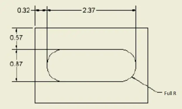
A full radius is a radius that smoothly blends into another surface. Full radius is most often specified in a rounded slot feature or a feature that mimics a rounded slot.

A full radius sometimes noted as a true radius or full R is outdated language and not part of the current revision of the drawing standard ASME Y14.5. The full radius callout is referencing a smooth transition from the radius to an adjacent surface.

full radius blueprint example

How to measure a full radius

Because no reference standard documents the requirements of a full radius, there are no specific requirements for the callout.

When a full radius, true radius or full R is called out on the drawing, the blueprint drafter is attempting to control the blend into and out of the specified radius.

What is a full radius?

A full radius is a radius that smoothly blends into another surface. Full radius is most often specified in a rounded slot feature or a feature that mimics a rounded slot.

A full radius sometimes noted as a true radius or full R is outdated language and not part of the current revision of the drawing standard ASME Y14.5. The full radius callout is referencing a smooth transition from the radius to an adjacent surface.

full radius blueprint example

How to measure a full radius

Because no reference standard documents the requirements of a full radius, there are no specific requirements for the callout.

When a full radius, true radius or full R is called out on the drawing, the blueprint drafter is attempting to control the blend into and out of the specified radius.

Full radius vs radius

There is no difference between the drawing callouts of full radius, true radius and radius. Because there are no specific requirements for a full radius referenced by any drawing or GD&T standards, there is no difference in the requirements of a full radius or full R vs a radius or R. A full radius does not have a tolerance. A radius if drawn correctly will have some form of a +/- tolerance or be controlled through a GD&T requirement such as profile or cylindricity.

There is no difference between the requirements of the example below or the previous one.
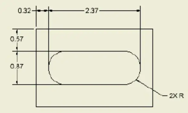
full radius blueprint example

Want to learn more?

GD&T is a complicated subject and understanding it correctly can be the difference between a perfect part and scrap.

The best way to learn GD&T is from experienced teachers who can break down the material into manageable pieces.

Luckily, we know someone.

And MachinistGuides.com readers get an exclusive discount on training!

Get the Best GD&T Training Available

Related Articles

For more information see these related articles:

Facebook Twitter Youtube

Full radius vs radius

There is no difference between the drawing callouts of full radius, true radius and radius. Because there are no specific requirements for a full radius referenced by any drawing or GD&T standards, there is no difference in the requirements of a full radius or full R vs a radius or R. A full radius does not have a tolerance. A radius if drawn correctly will have some form of a +/- tolerance or be controlled through a GD&T requirement such as profile or cylindricity.

There is no difference between the requirements of the example below or the previous one.

full radius blueprint example

Want to learn more?

GD&T is a complicated subject and understanding it correctly can be the difference between a perfect part and scrap.

The best way to learn GD&T is from experienced teachers who can break down the material into manageable pieces.

Luckily, we know someone.

And MachinistGuides.com readers get an exclusive discount on training!

Related Articles

TYP & Typical on Blueprints [What They Mean & How to Inspect Them]

What does typical mean on a blueprint?

Typical on an engineering drawing identifies a repeated feature. This is identical to a feature which is identified as 2x or 5x. 

A typical dimension callout will occasionally be followed by a 2x, 5x or similar, to specify the quantity of features which are tolerance the same. 

The typical callout will most often be used as part of a repeating pattern such as a bolt hole circle, to identify the hole sizes or angle between the holes. 

Another common application is to identify a common chamfer size on a component. It should be noted that the notation of “typical” is not a part of the current revision of the ASME Y14.5 standard and therefore not a recommended notation for use on an engineering drawing. There are however countless blueprints in the wild which may already use this language.

What is the symbol for a typical dimension?

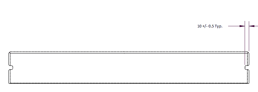
There is no GD&T symbol for a typical dimension. A typical dimension callout is identified with either TYP. or TYPICAL. In the example below, the typical notation is used to reference that the slot on both sides of the part is to be machined to the same depth.

typical callout blueprint example

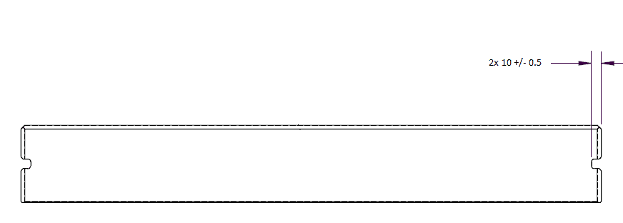
A better way to identify the same dimension would be as shown below. It is best to not leave anything to the imagination of the person interpreting the blueprint.

slot depth blueprint example

Want to learn more?

GD&T is a complicated subject and understanding it correctly can be the difference between a perfect part and scrap.

The best way to learn GD&T is from experienced teachers who can break down the material into manageable pieces.

Luckily, we know someone.

And MachinistGuides.com readers get an exclusive discount on training!

Rexbeti 0-1″ Digital Micrometer Review

plus symbol

Pros

Cheap price
Accuracy

minus symbol

Cons

Few extra features

Features

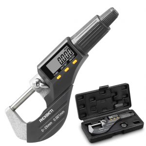
Rexbeti isn’t exactly a household name when it comes to inspection tools such as this 0-1” digital micrometer. What it lacks in name recognition, it makes up for in price but the question is can the quality keep up?
The Rexbeti 0-1” digital micrometer has a .00005” or .001mm resolution which is standard for most digital micrometers. It has an accuracy of +/- .0001” which is only slightly worse than some of the best digital mics such as this one from Mitutoyo but better than most budget options. Prices fluctuate some but the Rexbeti sacrifices very little in accuracy while cutting the cost dramatically.
The digital readout on this set of micrometers is large and easy to read. The display has a simple button layout with only 3 buttons on the face. These primary buttons are on/off, one for switching units between inches and millimeters, and one for zeroing the tool.

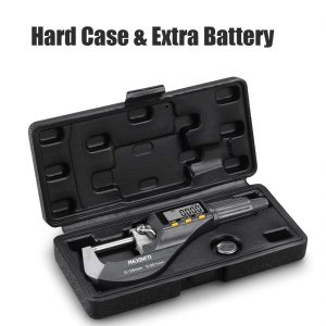
The Rexbeti 0-1” digital micrometer features a ratchet stop for taking consistent measurements. The ratchet stop when used correctly allows the user to exert a controlled amount of force when taking readings. This results in more accurate and consistent measurements. Additionally, when not in use this digital mic has an auto shut off feature to save battery life. The tool also comes with an extra battery and a protective case for storage.

Verdict

Beyond these simple features this Rexbeti micrometer doesn’t have anything too fancy going on. What it lacks in extras though, it makes up for in accuracy. When compared to many other budget digital micrometers, its accuracy stands out for the price. These Rexbeti 0-1” digital micrometers are a great buy at the price and capable of measuring up to all but the most precise digital micrometers.

iGaging 0-1″ Digital Micrometer Review

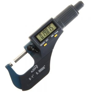
igaging digital micrometer
plus symbol

Pros

Extra features
Display

minus symbol

Cons

Battery life

Features

iGaging is a popular brand for budget friendly inspection tools. This set of digital micrometers is no different. They have a measuring resolution of .00005” or .001mm and an accuracy of +/- .00015” which equates to +/- .003mm. While not as good as some digital micrometers which cost 2-3 times as much, the iGaging digital mics come close at a fraction of the price.
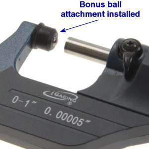
ball attachment for igaging digital micrometer
These iGaging digital micrometers have a very impressive feature set. Some of the extras that aren’t normally seen in its price range are a SPC output and a ball attachment for the anvil. The SPC output allows you to record measurements directly to your computer while the ball attachment allows you to measure round surfaces such as the wall thickness of tubing. Some of the more standard type features include an extra battery and a protective case to keep your tool safe. Carbide tips are a nice bonus that isn’t always seen on budget level digital micrometers. They provide superior wear resistance when compared to normal hardened steel.
A decent size display and simple button layout adorn the face of the tool. With the press of a button the micrometer switches units from inches to millimeters. The ability to switch between absolute and incremental measuring modes is available too. Nothing too out of the ordinary present in the normal use of the mic.
Like most other digital micrometers, this one from iGaging has a little more weight to it than a standard micrometer. Some don’t like the added weight because they feel it makes it harder to maneuver around their workpiece. With a little time and use, I don’t believe the weight will bother anyone.
Now onto some of the negatives. The biggest problem is that some buyers report instances of the display flickering. All of the budget digital micrometers have quality issues such as this one, the bigger problem is that the manufacturer isn’t the most responsive to problems. Another common issue for lower priced tools is limited battery life. For most this shouldn’t be too much of a bother but it’s best to keep an extra battery or two on hand. Lastly, the thimble feels cheap because of the plastic material used.
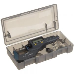
igaging digital micrometer in case

Verdict

The simplicity of the display and button layout are a nice touch and will be appreciated by those not as familiar with digital micrometers. The addition of the SPC output and ball attachment put these mics a step above most other entry level digital micrometers. To get a better micrometer you will need to pay 3 times the cost of these mics or more. The iGaging 0-1” digital micrometer is a solid budget priced inspection tool.

Engineering, Manufacturing and Quality Abbreviations and Acronyms

abbreviations and acronyms word bubble

OMG why are there so many acronyms and abbreviations? FYI here is a huge list of common meanings. Hopefully it helps decipher some of the jargon and gibberish. 

8D – method of problem solving commonly used in the automotive industry.

AQL – acceptance quality limit, previously acceptable quality limit

APQP – advanced quality product planning

AS9100 – aerospace quality standard

ATP – acceptance test procedure

BOM – bill of materials

CAD – computer aided design

CAGE – Commercial and Government Entity code

CAM – computer aided manufacturing

CAPA – corrective and preventive action

CAR – corrective action report

CFE – customer furnished equipment

CFM – customer furnished material

CNC – computer numerical control

COA/C of A – certificate of analysis

COC/C of C – certificate of conformance or certificate of compliance

COTS – commercial off the shelf

CSM – customer supplied material

CT – center thickness

DFARS – Defense Federal Acquisition Regulation Supplement

DFMEA – design failure mode effects analysis

DPA – destructive physical analysis

DPAS – Defense Property Accountability System

DPPM – defective parts per million

DSS – data summary sheet

ECN – engineering change notice

EIDP – end item data package

ERP – enterprise resource planning

ESD – electrostatic discharge

ETV – edge thickness variation

FAI – first article inspection

FAIR – first article inspection report

FMEA – failure mode and effects analysis

FOB – free on board

FOD – foreign object damage

FW – face width

GFE – government furnished equipment

GFM – government furnished material

GFP – government furnished property

GIDEP – government industry data exchange program

GMIP – government mandatory inspection points

GSI – government source inspection

GSS – government source surveillance

HIC – humidity indicator card

IAQG – International Aerospace Quality Group

IAW – in accordance with

IOT – internet of things

ISO – International Organization for Standardization

ITAR – International Traffic in Arms Regulation

JIT – just in time

KPI – key performance indicator

MBB – moisture barrier bag

MRB – material review board

MSDS – material safety data sheet

NADCAP – National Aerospace and Defense Contractors Accreditation Program

NC – non conformance

NCM – non conforming material

NDT – non destructive testing

NIST – National Institute of Standards and Technology

OCM – original component manufacturer

OD – outside diameter

ODM – original design manufacturer

OEM – original equipment manufacturer

OTD – on-time delivery

PCB – printed circuit board

PDCA – plan, do, check, act

PEM – plastic encapsulated microcircuits

PFMEA – process failure mode and effects analysis

PID – product identification document

PL – parts list

PM – preventative maintenance

PPAP – Production Part Approval Process

PO – purchase order

QA – quality assurance

QAPP – quality assurance program plan

QC – quality control

QML – qualified manufacturers list

QPL – qualified product list

QTP – qualification test plan

QTR – qualification test report

RCA – root cause analysis

REACH – registration, evaluation, authorization and restriction of chemicals

RFI – request for information

RFQ – request for quote

RMA – return material authorization

RoHS – Restriction of Hazardous Substances

SCAR – supplier corrective action request

SDS – safety data sheets

SMP – supplier management process

SOP – standard operating procedure

SOW – scope of work

SPC – statistical process control

TDP – technical data package

TIR – total indicator runout

WI – work instruction

WIP – work in progress

XRF – x-ray fluorescence

Ballooning/Numbering A Blueprint

What is a ballooned or numbered blueprint?

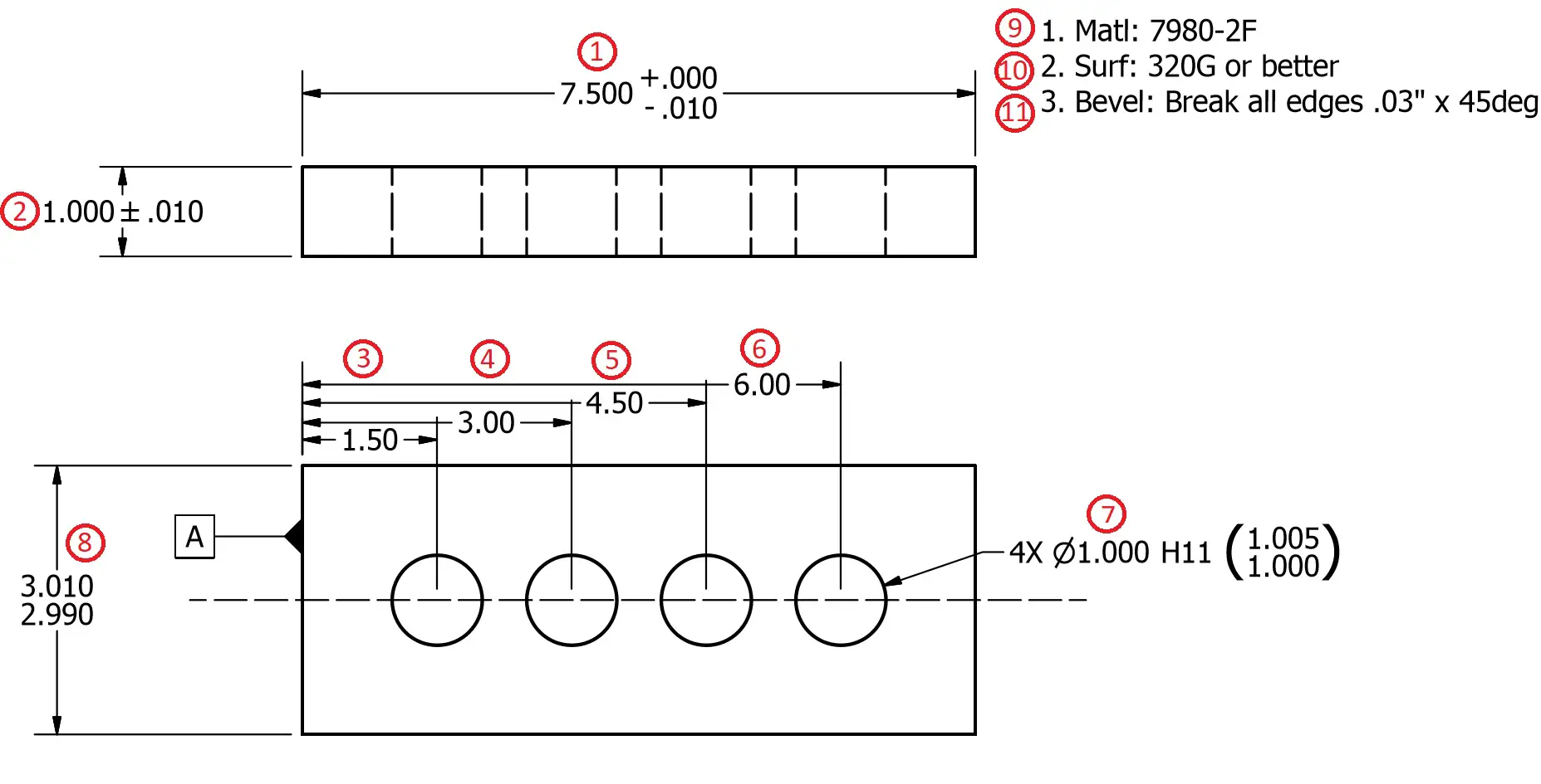
ballooned drawing example

Commonly referred to by many different names including ballooned drawing, bubble drawing, numbered print, etc. A numbered drawing or blueprint is a way to identify individual attributes of a part or assembly as depicted in an engineering drawing. The numbers and balloons or bubbles are ordinarily done in red ink or a red font as seen above.

What are ballooned drawings used for?

Numbered drawings are a common component in the inspection process. They can be a part of your in house inspection procedure or a requirement which you provide to your customers. Ballooned drawings are also frequently used as part of a first article inspection report package. They allow the reader to connect an individual measurement to its location on the blueprint. This is especially handy when multiple attributes with the same nominal values are present.

How to number a drawing

Numbering or ballooning a blueprint is a process that has some flexibility to the order in which attributes are labeled. The most important aspect is that all attributes are assigned a number including all notes and general tolerances as needed. When in doubt, number it. Where to start is a matter of preference but make sure that your numbering sequence is easy to follow. Generally the person numbering the drawing will start in the top left view and work their way clockwise assigning numbers to attributes in that particular view. This process is repeated for all views present on the drawing in a top to bottom, left to right manner similar to the way you read a book. Some users will list attributes in the notes first such as material, but this is simply a matter of preference. Just make sure to number all the relevant attributes in the notes. If you work in a logical manner, it will be much easier for the customer or reader to follow along.

Example of a fully numbered drawing

What to include in a numbered drawing

Assign a number to every attribute on the print including all notes and applicable general tolerances. Some notes may include more than one attribute in a single note which requires a numbered attribute.

Related Articles

Datums – All About

What is a datum?

A datum is a reference point for measurements. A datum is a theoretically perfect feature. It is often a main surface of a part called a plane but can also be a point such as the center of a diameter or an axis such as the center of a cylinder.

How are datums used?

Datums are used to orient measurements. In the case of something simple such as a perpendicularity specification, the datum is the surface against which the toleranced feature is checked. For a positional tolerance, features are located relative to a datum.

Symbol for a datum

Datum Blueprint GD&T Symbol a in a box with arrow

Datum names

Datum names are identified with a capital letter. The most important reference feature is usually identified with a capital A. In order of importance datums will be assigned consecutive letters (B, C, etc).

How is a datum used in a feature control frame?

feature control frame description with parts identified

Datums are placed at the end of a feature control frame.

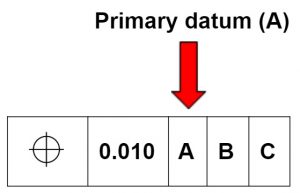
Primary datums

primary datum identifier

A primary datum is the main locating surface used for alignment.

Think of a box set on a table. In this case the bottom of the box is the primary datum.

The table would be used to simulate the primary datum. In this example measurements could be taken from the table to other features of the box to verify they meet the required dimensions.

The primary datum controls one axis of freedom. The box can move back and forth or spin in place on the table but it can not turn end over end. This is similar to the way a granite surface plate is used in machine shops all over the world.

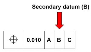
Secondary datums

secondary datum identifier

A secondary datum is the secondary alignment feature. In the box on a table example, if the table and the box were pushed up against a wall then the wall would be the secondary datum.

The box would contact the wall at a minimum of two points. Contacting the wall would constrain the movement in another axis.

The table controls end over end movement. The wall stops the box from spinning. It is however still able to move back and forth along the wall.

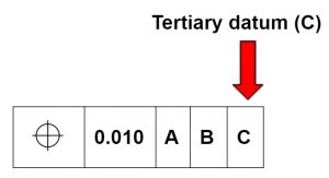
Tertiary datums

tertiary datum identifier
A tertiary datum is the third alignment feature. In the box on a table example, if the box on a table which is now against a wall was pushed into a corner then the new wall would be the tertiary datum. This new datum works to control the last remaining axis of movement.

What is a datum target?

A datum target is a specified location that is used to measure a part. It identifies the point(s) from which measurements will be taken.

The use of datum targets or points provides a level of control over the datum surface. Some surfaces are incapable of being used like a normal datum.

A very large datum surface or a surface that has a lot of variation in its form are two common reasons why datum targets are used.

Datum targets are also used to mimic real world use such as contact points in an assembly.

Datum target symbol

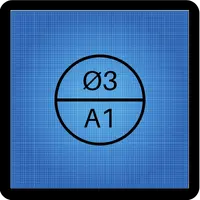
Datum Target Blueprint GD&T Symbol circle with diameter 3 in top and A1 in bottom half

The top half of the datum target symbol is often empty. The upper half lists the area of the datum target when specified. The lower half of the datum target symbol lists the datum target name. 

Is a datum real or theoretical?

Both really. The real datum is the actual surface referenced. This surface is imperfect and will have variation to it.

No surface is perfectly true.

In practice though a datum is used as a theoretically perfect surface.

A good example would be placing a datum surface down on a surface plate which is known to be very flat. The imperfect actual surface of the part will come to rest on the high points sitting on the surface plate. Measurements can be taken from the surface plate as if it was the datum surface itself.

Examples

true position callout

True position callout referencing datums A & B

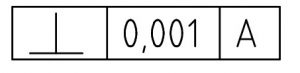
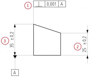
perpendicularity callout example with feature control frame

Perpendicularity callout referencing datum A

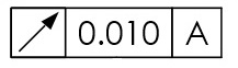
circular runout callout

Circular runout referencing datum A

Datum dimensioning vs chain dimensioning

Chain dimensioning is the process of dimensioning features of one another in a row. Datum dimensioning is used when features are referenced from a common point. Take a look at the differences in the examples below.

datum dimensioning blueprint example
Datum Dimensioning
chain dimensioning blueprint example
Chain Dimensioning

A disadvantage of chain dimensioning is that the tolerances stack up. This means that the location of the far right hole can actually vary by as much as +/- 0.040”.

The example which uses datum dimensioning maintains the +/- 0.010” tolerance for each location. Chain dimensioning can be a perfectly acceptable way to tolerance your parts, just make sure you have taken into account the additional tolerance that can apply to the feature.

Plural of datum

Nothing too strange. More than one datum would be multiple datums.

Want to learn more?

GD&T is a complicated subject and understanding it correctly can be the difference between a perfect part and scrap.

The best way to learn GD&T is from experienced teachers who can break down the material into manageable pieces.

Luckily, we know someone.

And MachinistGuides.com readers get an exclusive discount on training!

Related Articles

Feature Control Frames – All About

What is a feature control frame?

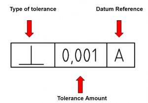
A key component of geometric dimensioning and tolerancing (commonly referred to as GD&T). On engineering blueprints, the feature control frame consists of a symbol to identify the type of tolerance, the amount of tolerance and reference datums if applicable.

How to read a feature control frame

A feature control frame is read from left to right. It reads “Type of control” of “Tolerance” to Datum. It should be noted that if a diameter symbol is present before “Tolerance” then it indicates the shape of the tolerance zone is cylindrical.

Examples

true position callout

True position of 0.2 to datums A and B

perpendicularity callout example with feature control frame

Perpendicularity of 0.001 to datum A

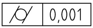
cylindricity callout

Cylindricity of 0.001

circular runout callout

Circular runout of 0.010 to datum A

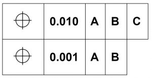
Composite feature control frame

A composite feature control frame controls both a pattern on a part and the location of individual items in the pattern. 

The upper section of a composite feature control frame specifies the tolerance for the pattern to the overall part. 

The lower section specifies the tolerance for individual features to the pattern. In the example of a bolt hole circle, the upper section controls the tolerance for the location of the bolt hole circle on the part. The lower section would control how closely the individual holes must follow the pattern.

composite feature control frame

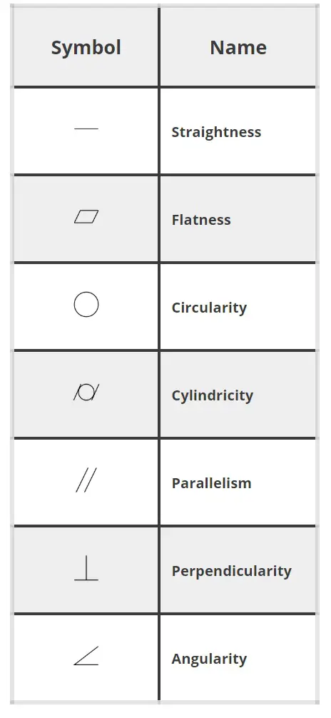
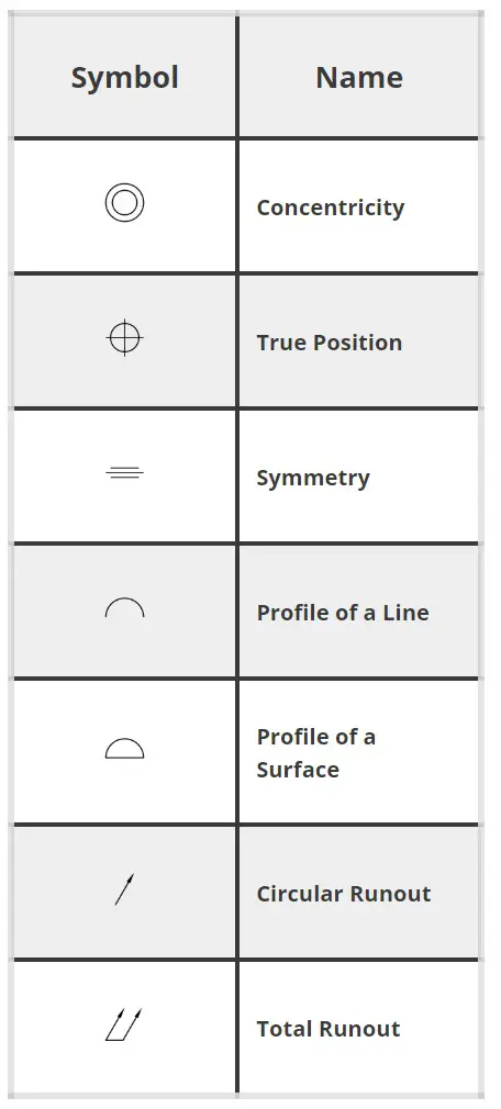
Feature control frame symbols

gd&t symbols
gd&t symbols

For more information see our GD&T Symbols Quick Reference
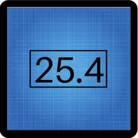
Basic dimensions

Basic Dimension Blueprint GD&T Symbol dimension in a box

Basic dimensions are identified by a rectangular frame around the dimension. 

They are dimensions that are theoretically exact. They do not have a tolerance themselves (general blueprint tolerances do not apply). 

Instead they are controlled by another characteristic. This is often seen with positional tolerances such as the true position of a hole. The hole location will be specified as basic dimensions. 

A true position tolerance will then be assigned to the hole which will control how far off the nominal location the hole can be.

Want to learn more?

GD&T is a complicated subject and understanding it correctly can be the difference between a perfect part and scrap.
The best way to learn GD&T is from experienced teachers who can break down the material into manageable pieces.

Luckily, we know someone.

And MachinistGuides.com readers get an exclusive discount on training!

Related Articles

iGaging Absolute Origin Digital Caliper Review

plus symbol

Pros

IP54 protection
2 year warranty

minus symbol

Cons

Reliability issues
Errors in measurement when the battery is low

Features

The iGaging Absolute Origin 0-6” digital calipers are made of hardened stainless steel. Capable of taking inside, outside and depth measurements like most calipers, they have an accuracy of +/- .001” or .02mm. They have a resolution of .0005” or .01mm. These calipers from iGaging are capable of measuring in inches and millimeters. Fractional measurements are available on a more expensive version of the same caliper. They also have a lock screw which makes taking repetitive measurements easier.

The display is not as large as some other caliper models but it is easy to read. Unfortunately there is no auto off or auto on feature for the display. Remember to turn the tool off after use. The iGaging caliper has been noted to have measurement errors when the battery is low. This wouldn’t be as much of an issue if there was some kind of indicator that the battery was low. The caliper comes with a spare battery which will help alleviate the problem but some of the reported errors could be quite hard to detect. 

 This digital caliper does come with some nice extras and features not always seen in its price range. Most importantly is IP54 protection. The IP stands for ingress protection. The 5 is the level of protection from solids such as dirt. The 4 is protection from liquids such as water or coolant. This equates to being protected from dust and from splashing water. Protection from contamination is not often seen with digital calipers in a budget price range. Even with more expensive name brand calipers, IP54 is not a common feature unless paying more for a specialty tool with this feature.

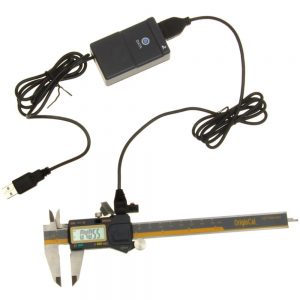
igaging digital caliper with spc cable

Additionally the iGaging caliper comes with a nice protective case and a SPC output. The SPC output allows the caliper to be connected to a computer for recording measurements. The version of the caliper that comes with the cable to connect to your computer is relatively expensive though. The cable more than doubles the cost of the caliper. 

 One of the best features of the iGaging Absolute Origin digital caliper is that it comes with a full 2 year warranty. Unfortunately, there is a possibility that you will need to use it. Plenty of other reviewers on Amazon have noted that the tool either stopped working altogether or gave erroneous measurements.

Verdict

The iGaging caliper has some very nice features such as IP54 protection and a SPC output. The errors in measurement that occur with a low battery and the general reliability regrettably outweigh them. The generous warranty helps make up for some of the tool’s shortcomings but ultimately a measuring tool such as a caliper needs to be dependable. The iGaging caliper lacks that dependability.

A Beginner’s Guide to Depth Micrometers

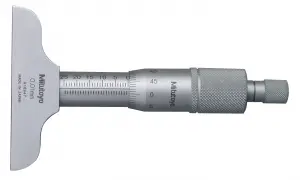
mitutoyo depth micrometer

What is a depth micrometer?

A depth micrometer (or depth mic) is a measuring tool commonly used to check precise measurements of slots, keyways, grooves and various other locations. They are a very accurate measuring device. 

Depth micrometers are commonly used to take measurements to an accuracy of .001″ or .0001″ in inches. Measurements in millimeters can be made down to .01mm or .001mm.

How to use a depth micrometer

Depth mics can be used to measure many different types of part characteristics. I will explain how to check a hole depth. 

Before using your micrometer, ensure that the measuring tool and surface to be measured are free of dirt, debris, chips, etc. The micrometer thimble should spin freely.  Place the tool on part over the hole. Spin the micrometer thimble until the rod extends to the bottom of the hole. Use the ratchet or friction stop if available on your tool.

depth micrometer rod
A depth micrometer rod

Note: The depth mic should be checked for accuracy whenever a rod is changed to measure a different size. It can be easy for something to get contamination in between the micrometer and the depth rod where they come together. 

Keeping things as clean as possible will help with this problem.

How to read a depth micrometer

I recommend a digital depth micrometer for ease of measurement especially if the measurer will only occasionally be taking readings with their micrometer. Unfortunately the price of a digital depth mic can be quite high so if you must use an analog micrometer then please keep reading. 

The most common varieties of depth micrometers read in increments of one thousandth of an inch (.001″) or one ten-thousandth of an inch (.0001″). The process of reading a measurement from either type is similar. Along the sleeve of the depth micrometer will be graduations similar to a ruler. 

The graduations at every fourth interval are most often numbered 0, 1, 2 and so forth. These numbers represent .100″ or one hundred thousandths of an inch. If using a depth micrometer with a 1-2″ rod, the graduation marked 6 would correspond to a measurement of 1.600″. The graduations between the numbers are each .025″ or twenty five thousandths of an inch. If we were to use a depth micrometer with a 4-5″ rod and obtained a measurement at the 3rd graduation after the .200″ mark, then our reading would be 4.275″. This would be the reading if the 0 on the thimble lined up exactly with the 3rd graduation after the .200 mark on the reading line. 

If instead the number ten lined up with the reading line and we could still see the 3rd graduation after the .200″ mark, then our measurement would be 4.285″. For micrometers that read to .0001″ we would additionally rotate the micrometer without turning the spindle to determine which numbers line up on the sleeve and thimble. If a number lines up on the thimble with the number 7 on the sleeve, our reading would now be 4.2857″.

Formula for depth micrometer readings

Base depth micrometer rod size + (.100″ x largest visible number) + (.025″ x graduations visible after the largest number) + (.001″ x reading from thimble) +(.0001″ x reading from sleeve for .0001″ micrometers)

Example for a depth micrometer with a 1-2″ rod

1.000″ + (.100″ x 4) + (.025″ x 2) + (.001″ x 3) + (.0001″ x 8) =

1.000″+ .400″ + .050″ + .003″ + .0008″ = 1.4538″

When to use a depth micrometer

Depth micrometers while very accurate have one downfall. Depth micrometers like most standard micrometers are most commonly found in 1″ measuring range increments (3-4″, 4-5″, etc.). For a depth micrometer, this means that multiple sized rods are needed to be capable of covering the measurer’s  measurement needs. Because of this depth micrometers are commonly sold in sets. 

A 0-3″ micrometer set will cover the needs of most applications while a 0-12″ set is more than most people, especially hobbyists will need.

What makes a good depth micrometer

A good depth micrometer needs two things: precision and accuracy. Some adjustments can be made with most depth micrometers to account for small errors in accuracy but nothing can be done to fix a tool that isn’t precise. 

Quality depth micrometers will turn smoothly without any drag. This is the telltale sign of a good tool. If your depth micrometer ever feels like it is rubbing internally, disassemble the micrometer and clean per the manufacturers instructions to eliminate any possible contamination that may be causing the issue.

Where to buy depth micrometers

Depth micrometers are available from a number of online retailers. For a more in depth guide of which depth micrometer is best for your situation, please see our reviews section

Some general advice, as usual for most products Amazon has a number of good options available. Walmart sells depth micrometers but we do not recommend any that they currently offer.

Are cheaper depth micrometers as good as expensive ones?

While some of the cheaper (made in China) type depth micrometers have gotten much better than they were in years past, they are nowhere near the same quality that you will see in a depth micrometer from one of the tried and true manufacturers such as Starrett or Mitutoyo. 

A depth micrometer is the type of tool that is best to purchase once. In most cases it can be more beneficial to search for a used option on Craigslist or Facebook marketplace. Ebay can also be a good alternative. For more information on the best depth micrometers for your application, see our Best Depth Micrometers article.

How to calibrate a 0-1" depth micrometer

  1. Verify that the micrometer is clean.
  2. Visually examine the micrometer for any condition that could cause errors in the calibration.
  3. Whenever necessary to disassemble for adjustment, use care and cleanliness to assure no damage to the internal threads of the tool.
  4. Spin the thimble until the depth rod is inside the tool.
  5. Place the tool on a surface plate and spin the thimble to extend the depth rod to the zero position. Use the ratchet or friction stop if available.
  6. Repeat the process by placing the depth micrometer on gage blocks and overhanging the tool to allow the depth rod to extend down to the surface plate.
  7. Check accuracy of the micrometer at various locations within the tool’s measuring range. Gage blocks which have been calibrated themselves should be use for this operation. Block sizes which are used should test the micrometer at different positions of the thimble and not only increments of .025″. This ensures the scale on the thimble is accurate.
  8. Adjustments can be made at this step as needed. Different depth micrometers have different procedures for adjustment. Consult manufacturer documentation for instructions regarding the adjustment of your micrometer if needed. If adjustments are made, the calibration procedure should be started over to verify the adjustments were adequate. 
  9. Calibration results are commonly recorded in a register or database for traceability of measurement history.

Related articles