Knurling – All About

What is knurling?

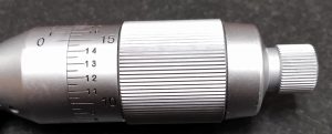
Knurling is the process of creating a pattern on a workpiece to improve the visual appearance or to create a better grip on the part. Knurling uses the tool to displace material. This moving of the workpiece material creates the knurled pattern. A great example of knurling is seen on the thimble of most micrometers. Knurling is also often used on various knobs to provide grip.

Types of knurling

straight knurling example
Straight knurling
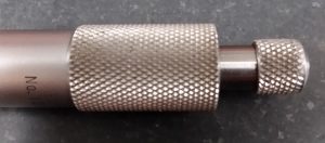
diamond knurling example
Diamond knurling

There are four main types of knurling. These are straight knurling, diamond knurling, left hand and right hand knurling. Of these different knurling types, straight and diamond are by far the most commonly used. There are many variations of these patterns including fine, medium, and coarse versions of each. Fine knurling has the lowest profile whereas coarse knurling would have prominent ridges to provide greater friction for gripping.

Cut knurling vs form knurling

Cut and form knurling are the two methods of creating knurling.

Form knurling is the standard form of knurling. Form knurling is pressing the knurling tool into the workpiece to create the raised grooves or teeth.

Cut knurling scrapes away material instead to create the knurling pattern. Cut knurling is better for some materials such as plastic or Delrin.

Does knurling increase diameter?

Form knurling does increase the diameter of the workpiece. This happens because the knurling tool is displacing material (moving it) which pushes material in in some locations and out in others. The amount of increase depends upon whether the knurling is fine or coarse. Coarse knurling has more material displaced and therefore creates bigger valleys and mountains in the workpiece.

Cut knurling decreases the diameter of the workpiece. This occurs because material is removed from the part instead of moved around like in form knurling.

Can you knurl wood?

Yes, wood can be knurled but it is not as simple as knurling metal. Knurling really only works for hard woods in the same way as metal. However, a simple pattern can be created through a process called checkering.  

Can you knurl plastic?

Plastics can be knurled though usually in a different way. Cut knurling is often used instead of standard form knurling.

Can you knurl Delrin?

Yes, you can knurl acetal plastic, also known as Delrin. It will be more difficult than knurling metal but if you manage you speeds, feeds, and depth of cut carefully then you can come out with something that looks nice and is functional. Cut knurling is a good choice for Delrin.

Knurling tips

Do your knurling before your final finishing. Knurling applies pressure to the workpiece and can bend it.

Because the force on the workpiece is so big, make sure that everything is secure including the part and the cutter.

Multiple passes frequently yield the best results

Thoughts?

Got any knurling tips? Share them and we will add them to the list.

Thru Hole – All About

What is a thru holes?

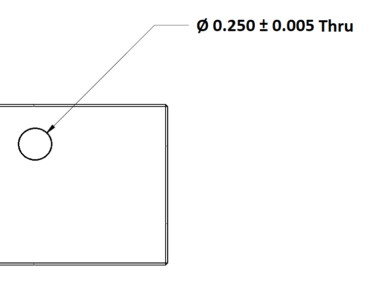
A thru hole, also known as a through hole, is a feature on a blueprint or drawing that identifies a hole to be machined with two open ends. The hole goes all the way through the part. In other words, the hole breaks through at two locations on the part.

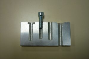
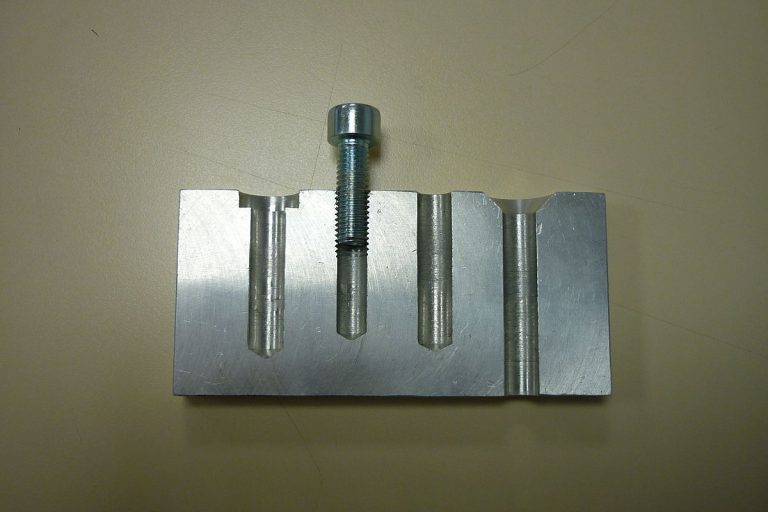
In the picture below, the thru hole is on the right. The other holes are blind holes.

cutaway example of blind and thru holes

How to dimension a thru hole?

A thru hole is dimensioned by specifying the diameter of the hole along with a tolerance. Additional features can be added if needed such as a countersink or counterbore for the hole. No other features are required.

Thru hole vs blind hole

A thru hole has two open ends. A blind hole has one open end and does not go all the way through the part.

Thru hole symbol

There is no GD&T symbol for a thru hole though often it will be specified with the notation “THRU” on the engineering drawing.

Thru hole examples

thru hole blueprint example

Want to learn more?

GD&T is a complicated subject and understanding it correctly can be the difference between a perfect part and scrap.

The best way to learn GD&T is from experienced teachers who can break down the material into manageable pieces.

Luckily, we know someone.

And MachinistGuides.com readers get an exclusive discount on training!

Blind Holes – All About

What is a blind hole?

A blind hole is a hole that does not go all the way through a part. A blind hole goes to a specified depth and stops. 

How to dimension a blind hole

To specify a blind hole requires listing the diameter of the hole and a dimension to control the depth. The depth can be controlled by directly specifying the depth of the hole or by identifying the amount of material that will remain.

Blind hole vs thru hole

cutaway example of blind and thru holes

A thru hole, sometimes called a through hole, goes completely through a part. It has two open ends whereas a blind hole has one open end and does not break through to the opposite side. In the image above, the three holes on the left are all blind holes. The hole on the right is a thru hole.

Blind hole symbol

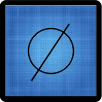
Diameter Blueprint GD&T Symbol o with line through it
Diameter symbol
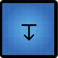
Depth Blueprint GD&T Symbol line with arrow pointing down
Depth of symbol

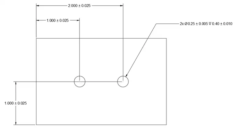
There is no GD&T symbol for a blind hole. A blind hole will be specified with a diameter and a depth specification or remaining amount of material. In the example below, the blind holes have a diameter of 0.25 and go to a depth of 0.40.

blind holes blueprint example

Can you make a flat-bottomed blind hole?

You can make a flat bottom blind hole, but it can be difficult depending upon what type of material is being drilled. A modified drill bit or an end mill can work.  This video explains some tips.

Blind hole example

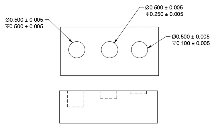
The example below has three blind holes. They all have a diameter of 0.500 but they have different depths. From left to right, the depths are 0.500, 0.250 and 0.100.

blind holes blueprint example

Want to learn more?

GD&T is a complicated subject and understanding it correctly can be the difference between a perfect part and scrap.

The best way to learn GD&T is from experienced teachers who can break down the material into manageable pieces.

Luckily, we know someone.

And MachinistGuides.com readers get an exclusive discount on training!

Limit Tolerances – All About

What is a limit tolerance?

limit tolerance example

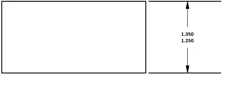
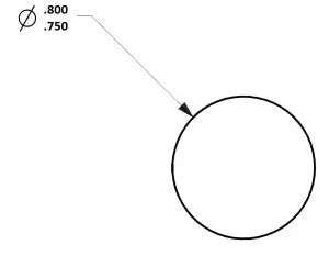
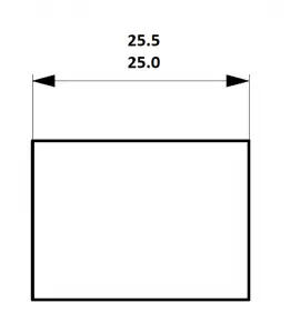
A limit tolerance is a form of dimensional tolerancing that specifies a tolerance range for a specific feature. Limit tolerances are also known as limit dimensioning and are an effective way to specify requirements on a blueprint. They clearly identify the tolerance range without requiring additional calculations by the blueprint reader.

Limit tolerance symbol

There is no GD&T symbol for a limit tolerance. Per ASME Y14.5, the notation for a limit tolerance is to callout the upper and lower tolerance boundaries for a dimension. The upper end value of the tolerance range goes on top of the lower end value as shown in the examples below.

Limit tolerance examples

limit tolerance example

Limit tolerance vs unilateral tolerance

unilateral tolerance blueprint example
Unilateral tolerance example

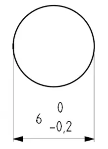
A unilateral tolerance lists a nominal value along with a plus or minus tolerance. Using these two values allows the blueprint reader to calculate the upper and lower ends of the tolerance range. A limit tolerance skips the calculation step and directly specifies the upper and lower end of the tolerance range. If the unilateral tolerance above was instead specified as a limit tolerance it would be 5.8-6.0.

Limit tolerance vs bilateral tolerance

bilateral tolerance blueprint example
Bilateral tolerance example

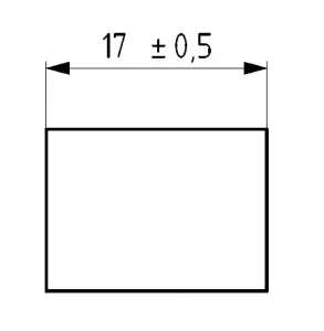
A bilateral tolerance lists a nominal value along with a plus/minus tolerance. Using these two values allows the blueprint reader to calculate the upper and lower ends of the tolerance range. A limit tolerance skips the calculation step and directly specifies the upper and lower end of the tolerance range. If the bilateral tolerance above were instead specified as a limit tolerance it would be 16.5-17.5.

Want to learn more?

GD&T is a complicated subject and understanding it correctly can be the difference between a perfect part and scrap.

The best way to learn GD&T is from experienced teachers who can break down the material into manageable pieces.

Luckily, we know someone.

And MachinistGuides.com readers get an exclusive discount on training!

Least Count – All About

What is least count in measurement?

Least count is the smallest possible measurement that a tool or measuring instrument can resolve. For example, if a measuring tape has graduations of 1/8” then the least count would be 1/8”. As the least count of a measuring tool gets smaller, it is capable of taking more accurate and precise measurements. A measuring tool such as a micrometer or digital caliper will have a smaller least count than a standard ruler. This means it is able to measure in smaller increments and therefore is more accurate.

What is the formula for calculating least count?

ruler

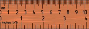
Least count is calculated by taking a known interval and dividing by the number of divisions.

Least count = known interval / number of division

In the case of the ruler above, in each 1 inch interval there are eight divisions. This means that the least count of the inch ruler is 1/8”.

For the mm side of the ruler, in each 1 mm interval there are ten divisions. This means that the least count of the mm ruler is 0.1mm.

Micrometer least count formula

parts of a micrometer

The formula for calculating the least count of a micrometer is:

Least count of micrometer = least count of main scale / number of divisions on secondary scale

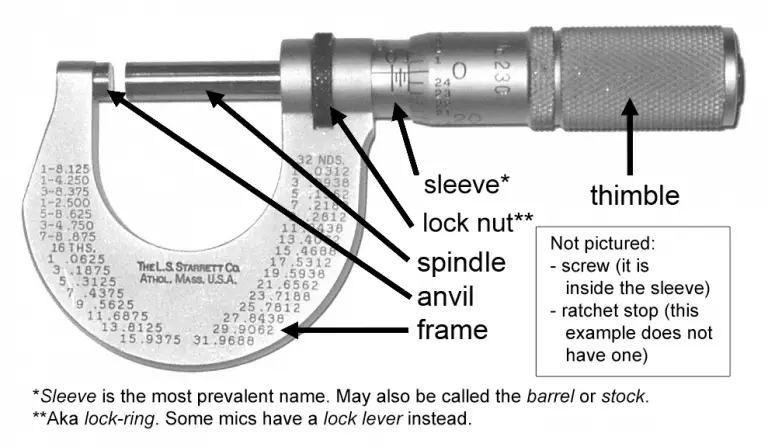
This is slightly different than our ruler example above. This is because a micrometer usually will have a secondary scale. The primary scale is along the sleeve of the micrometer while the secondary scale is around the thimble.

For most inch micrometers, the least count of the main scale is 0.025” and the number of divisions on the secondary scale is 25 therefore the least count would be 0.001”. Some micrometers have a tertiary scale around the sleeve. This third scale has 10 divisions. This allows the secondary scale to be read with greater accuracy. The least count of the secondary scale (0.001”) / number of divisions on tertiary scale (10) = 0.0001”.

For most metric micrometers, the least count of the main scale is 0.5mm and the number of divisions on the secondary scale is 50 therefore the least count would be 0.01mm.

Least count of vernier caliper

vernier caliper measuring inside diameter of brass part

The formula for calculating the least count of a micrometer is:

Least count of vernier caliper = least count of main scale / number of divisions on secondary scale

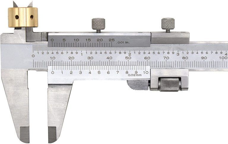
For most inch vernier calipers, the least count of the main scale is .025” and the number of divisions on the secondary scale is 25 therefore the least count would be .001”.

For most metric vernier calipers, the least count of the main scale is 1mm and the number of divisions on the secondary scale is 50 therefore the least count would be .02mm.

Least count of common length measuring instruments

Measuring instrument

Least count in inches

Least count in mm

Micrometer

.0001"

.001mm

Digital Micrometer

.0001"

.001mm

Dial Caliper

.001"

.01mm

Digital Caliper

.0005"

.01mm

Vernier Caliper

.001"

.02mm

Ruler

.100"

.1mm

Measuring tape

1/16"

1mm

Height gauge

.001"

.01mm

Dial indicator

.001"/.0001"

.01mm/.001mm

Spherometer

.0001"

.001mm

Micrometer screw

.0001"

.001mm

Spotfaces – All About

What is a spotface?

spotface example on part

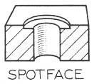
A spotface is a machined section of a part that allows a fastener to sit flat. This is usually a bolt head or washer but can be other fasteners. A spotface is generally very shallow and removes just enough material to create the clean, even, flat surface. Spotfaces are most often used when machining castings or forgings. Spotfacing is done using a manual or CNC milling machines.

Spotface vs counterbore

A spotface is functionally no different than a counterbore. A counterbore usually references a feature that is deeper than a spotface. While a spotface creates a flat mounting surface, a counterbore acts to recess the fastener. It would be safe to call a spotface a counterbore but not the other way around.

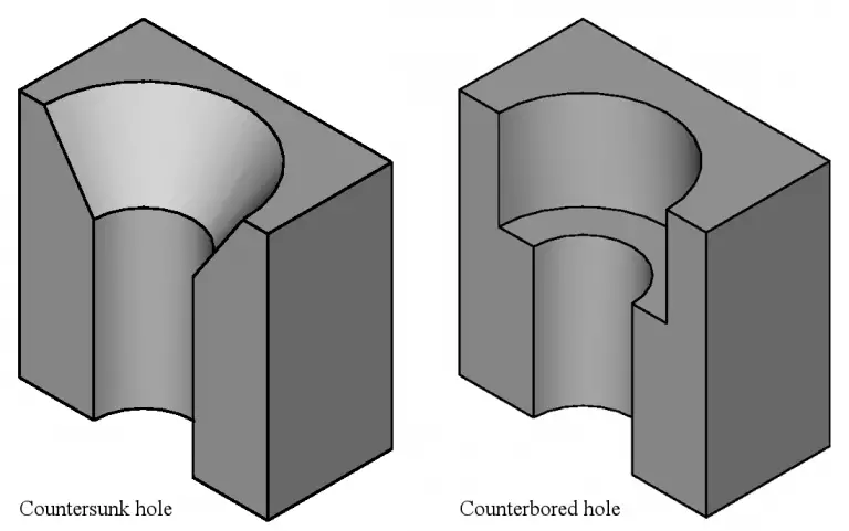
cutaway examples of countersink and counterbore

Spotface vs countersink

The primary difference between a countersink and a spotface is that the countersink has an angled bottom whereas a spotface has a flat bottom.

Spotface symbol

Spotface Blueprint GD&T Symbol SF in a u
Spotface symbol
Counterbore Blueprint GD&T Symbol u shape
Counterbore symbol

The symbol used to callout a spotface is the counterbore symbol with the letters SF in the middle. This is per the engineering drawing standard ASME Y14.5. At times, a blueprint may indicate a spotface feature simply through the use of a counterbore symbol. Additionally, older drawings and blueprints may reference a spotface as SF or SFACE instead of using the symbol.

How to dimension a spotface

spotface blueprint example

A spotface is dimensioned by specifying its diameter and depth. At times the amount of remaining material may be specified instead of the depth. The symbols for diameter and depth are shown below.

Diameter Blueprint GD&T Symbol o with line through it
Diameter symbol
Depth Blueprint GD&T Symbol line with arrow pointing down
Depth symbol

Spotface example

spotface cutaway example

Want to learn more?

GD&T is a complicated subject and understanding it correctly can be the difference between a perfect part and scrap.

The best way to learn GD&T is from experienced teachers who can break down the material into manageable pieces.

Luckily, we know someone.

And MachinistGuides.com readers get an exclusive discount on training!

Countersinks – All About

What is a countersink?

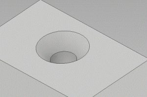
A countersink is an angled taper applied to a hole that allows a fastener (usually a flat head screw or similar) to sit even with, or below the surface which has been countersunk. Occasionally, a countersink is used simply as a method of chamfering or deburring a hole.

Countersink symbol

Countersink Blueprint GD&T Symbol two lines pointing down

The GD&T callout for a countersink is shown below. Some older blueprints may use the notation CSK to identify a countersink dimension.

If you want to type the ⌵ symbol, hold the ALT key and press 9013. See this list for other common keyboard shortcuts for GD&T and blueprint symbols.

How to dimension a countersink

countersink blueprint example

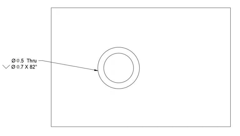
A countersink is dimensioned by specifying the diameter of the countersink where it meets the surface and the included angle. In the above example, the part has a 0.5 thru hole and a countersink with a diameter of 0.7 and an included angle of 82°.

How to measure a countersink

Countersinks can be measured by many different gauges. The easiest tool to use, assuming the tolerances aren’t too tight, is a pocket comparator with a reticle. Optical comparators and CMMs are regularly used to measure countersinks with very tight tolerances.

What does a countersink look like?

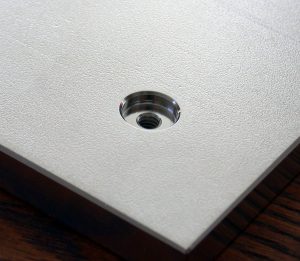
countersink example on part

Countersink vs chamfer

A countersink and a chamfer are very similar. A countersink is basically no different than a chamfer on a hole.

The main difference is that a chamfer is normally thought of as being at 45 degrees (though the angle can vary). A countersink is usually one of many different standard angle sizes.

The most common countersink angles are 82°, 90° or 100°.

Note that in the case of the 90° countersink, this callout is the same as a 45° chamfer because the countersink angle takes both sides into account, so it is twice the chamfer angle.

Countersink vs counterbore

cutaway examples of countersink and counterbore

The difference between a countersink and a counterbore is that a countersink has an angled bottom and a counterbore has a flat bottom. Countersinks are often used to recess a flat head screw. Counterbores are used to recess bolts, washers and other fasteners.

Countersink vs spotface

spotface example on part
Spotface example

A spotface has a flat bottom like a counterbore while a countersink is angled. A spotface is used to create a flat area in a specific location to allow a fastener such as a screw or bolt to sit squarely.

Want to learn more?

GD&T is a complicated subject and understanding it correctly can be the difference between a perfect part and scrap.

The best way to learn GD&T is from experienced teachers who can break down the material into manageable pieces.

Luckily, we know someone.

And MachinistGuides.com readers get an exclusive discount on training!

Counterbores – All About

What is a counterbore?

A counterbore is a circular hole with a flat bottom which coincides with another hole. The counterbored section allows a bolt head or other fastener to be recessed.

What does a counterbore look like?

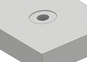
counterbore on metal part
An example of a counterbore in a piece of metal

Counterbore symbol

The GD&T callout for a counterbore is shown below. The counterbore symbol will often be used together with the diameter symbol and the depth symbol. Older blueprints may specify a counterbore with the notation CBORE instead of the counterbore symbol.

Counterbore Blueprint GD&T Symbol u shape
Counterbore symbol

If you want to type the ⌴ symbol, hold the ALT key and press 9012. See this list for other common keyboard shortcuts for GD&T and blueprint symbols.

How to dimension a counterbore

Diameter Blueprint GD&T Symbol o with line through it
Diameter symbol
Depth Blueprint GD&T Symbol line with arrow pointing down
Depth of symbol

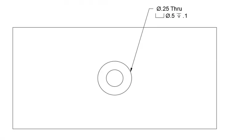
A counterbore is dimensioned by including the diameter of the counterbore along with specifying the depth. The two ways to specify the depth are to specify how deep the counterbore is or the thickness of the remaining material. Both methods are acceptable and commonly seen.

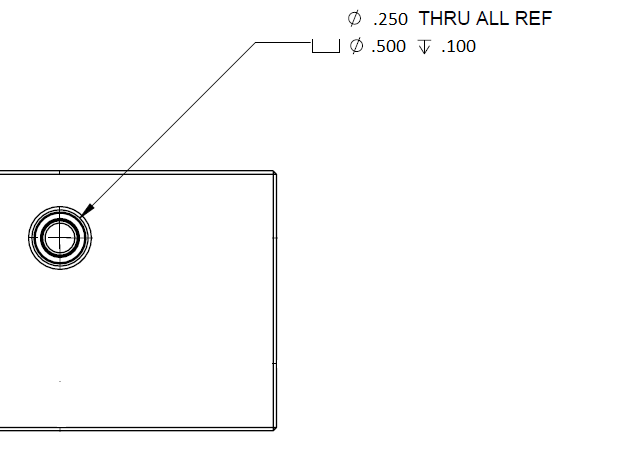
In the example below, the part has a .250 hole and a .500 diameter counterbore to a depth of .100.

counterbore blueprint example

How to measure a counterbore

Counterbores can be measured with many different types of gauges. The simplest inspection tool to use, assuming the tolerances aren’t too tight, would be a caliper.

Pocket comparators, gage pins, and depth micrometers are other types of measuring equipment that are frequently used to measure counterbores.

Counterbore vs countersink

cutaway examples of countersink and counterbore

The difference between a countersink and a counterbore is that a countersink has an angled bottom and a counterbore has a flat bottom. The angle of the countersink can vary with many different angles used such as 82°, 90° and 100°.

Counterbore vs spotface

spotface example on part

A counterbore and a spotface are very similar. A counterbore is used to recess a fastener while a spotface is used to create a flat surface located allow a fastener to be used. A spotface is used to let a fastener sit flat and in a specific location. A spotface is basically a shallow counterbore.

Want to learn more?

GD&T is a complicated subject and understanding it correctly can be the difference between a perfect part and scrap.

The best way to learn GD&T is from experienced teachers who can break down the material into manageable pieces.

Luckily, we know someone.

And MachinistGuides.com readers get an exclusive discount on training!

Tolerance Blocks – All About

What is a tolerance block?

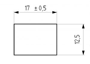
The definition of a tolerance block is a section on an engineering drawing or blueprint that identifies tolerances for a dimension that aren’t specifically called out on the print. Notice how the 17.5 dimension below has a tolerance directly associated with it.

Now look at the 12.5 dimension and notice that no tolerance is specified. Because there is no tolerance called out, the tolerance in a tolerance block (general tolerances) would be applied to this specific dimension.

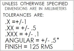
Note: The contents of the tolerance block are often referred to as the general tolerances. Depending on the units used on the blueprint, the tolerance block can be specified in metric or imperial (inch) units.

Tolerance block examples

tolerance block example

How to read a tolerance block

Most tolerance blocks are identified based on the number of decimal places of the feature on the blueprint. 

Using our previous examples again, notice that the 12.5 dimension has one number after the decimal place. Based on the tolerance block, this would assign the +/- 1 mm tolerance to the dimension. 

If the dimension was instead 12.54 then the tolerance assigned would be +/- .5mm. Angular dimensions often are specified in the same way. In our example, all unspecified angular tolerances would be assigned the =/- .5° tolerance.

tolerance block example

Other names for a tolerance block

  • Default tolerances
  • General tolerances
  • Standard tolerances
  • Title block tolerances

Want to learn more?

GD&T is a complicated subject and understanding it correctly can be the difference between a perfect part and scrap.

The best way to learn GD&T is from experienced teachers who can break down the material into manageable pieces.

Luckily, we know someone.

And MachinistGuides.com readers get an exclusive discount on training!

Related articles

EAGems 0-6″ Digital Caliper Review

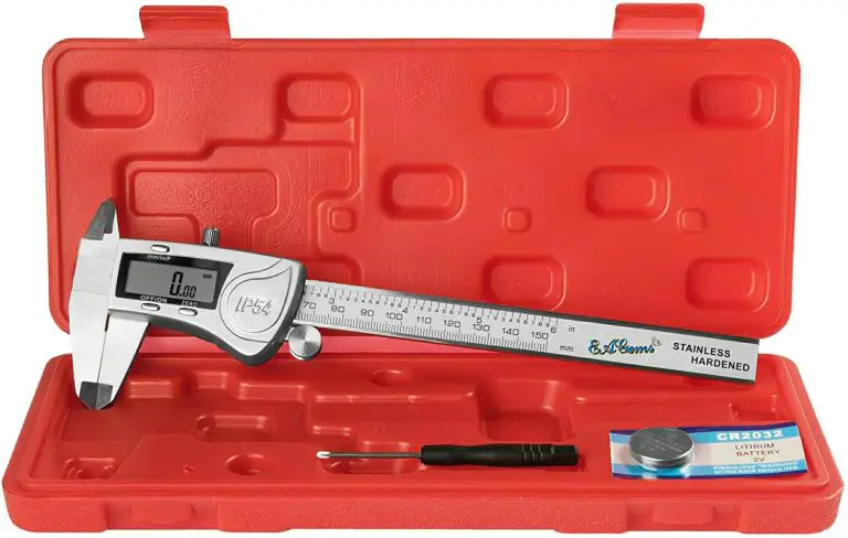
EAGems Caliper with case
plus symbol

Pros

IP54 protection rating
Two year warranty extended to three if registered
Responsive customer service

minus symbol

Pros

Stainless steel jaws

Features

The EAGems 0-6” digital caliper is a good value for the price. Made of stainless steel, it takes measurements in inch, metric and fractional units. The fractional unit mode is especially useful for those looking to use this caliper for woodworking inspection. Boasting an accuracy of +/- .0005”, .01mm or 1/64th of an inch, the EAGems caliper is in line with most other tools in the price range and even some that are more expensive. The included thumb roller on the tool makes it easier to take measurements. Often calipers in a cheaper price range such as this one will lack this feature. Combined with the measurement lock feature, this competes with much more expensive digital calipers such as the Mitutoyo 500-196-30 0-6” Digital Caliper. The EAGems (which is short for Edward Allen Gems) caliper is capable of taking inside, outside, depth and step measurements to the noted accuracy.

EAGems caliper display

The large, easy to read display takes a little getting used to because the fractional display makes the last two digits smaller. The display has an automatic on/off feature which is designed to save battery life. Depending on the level of use, the typical battery will last about a year. Speaking of batteries, the caliper comes with an extra battery to give the user approximately 2 years of battery life out of the box.

EAGems caliper features

Battery replacement for the caliper is a simple task. To replace the battery of the caliper, use the included screwdriver to remove the screw from the back of the tool and swap out with the included extra battery or another purchased battery.

ingress protection (IP) ratings solids description
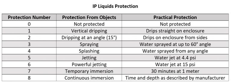
ingress protection (IP) ratings liquid protection

One of the best features of the EAGems caliper is the IP54 rating. Uncommon for a tool at this price point, the IP54 rating means that the caliper is protected against dust but not completely dust tight and protected against splashing water. Practically, this means the tool is resistant to most forms of normal contamination such as a coolant splash.

Verdict

For the price, the EAGems 0-6” digital caliper is a great tool. If you are looking for a quality measuring tool that won’t break the bank, keep this one in mind. While a caliper made by brands such as Mitutoyo might have a more proven level of reliability, this caliper is almost as good for about a third of the price. Don’t overlook the importance of the IP54 protection rating if you are going to be working in a very dusty environment or around splashing coolant. This is a valuable feature not included on many calipers that cost much more.