What is a unilateral tolerance?
Basically, a unilateral tolerance is a type of tolerance that is only allowed in one direction. Either an all plus tolerance or an all minus tolerance.
Here are some quick unilateral tolerance examples:
- 10.0mm +0/+0.5mm
- 5.515″ +0.010″/+0.015″
- 2.325″ +0/-0.005″
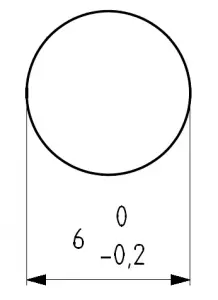
- 4.5mm -0.2/-0.3mm
Notice that in these examples, all of the allowed size variation is in one direction. The direction can be positive or negative and zero is allowed.
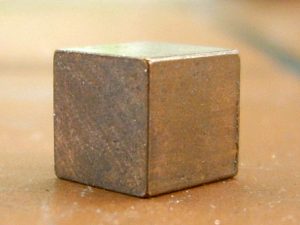
Unilateral tolerances are often used to specify dimensions that require a specific fit with a mating part.
Unilateral tolerance symbol
There is no GD&T symbol for a unilateral tolerance.
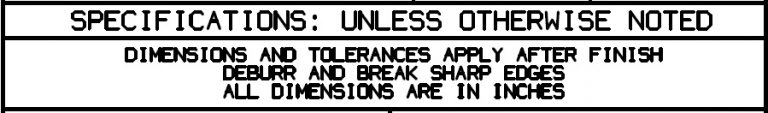
Per ASME Y14.5, the notation for a unilateral tolerance is to show a plus or a minus tolerance associated with a nominal dimension. It is acceptable for one of the specified tolerances to be zero.
Want to learn how to type GD&T symbols with no special fonts needed?
How to read a unilateral tolerance
Let’s start with our examples from above.
- 10.0mm +0/+0.5mm
- 5.515″ +0.010″/+0.015″
- 2.325″ +0/-0.005″
- 4.5mm -0.2/-0.3mm
Now let’s break it down so you can see what the nominal size is as well as the top and bottom ends of the tolerance zone.
Nominal Size | Bottom of Tolerance | Top of Tolerance |
10.0mm | 10.0mm | 10.5mm |
5.515" | 5.525" | 5.530" |
2.325" | 2.320" | 2.325" |
4.5mm | 4.2mm | 4.3mm |
Regardless of what the nominal size is, the requirement for each of these unilateral tolerance examples would be that the dimension must fall within the top and bottom tolerance range.
Unilateral tolerances compared to other tolerance types
Unilateral tolerance vs bilateral tolerance
A bilateral tolerance allows a tolerance in both directions.
A unilateral tolerance allows a tolerance in only one direction.
A bilateral tolerance is plus AND minus. A unilateral tolerance is a plus OR minus tolerance.
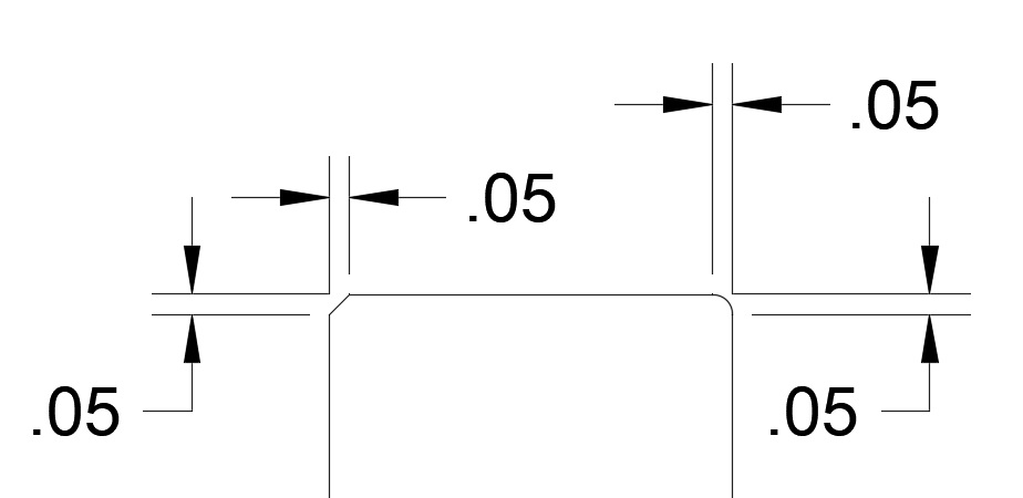
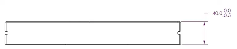
If we take the unilateral tolerance from the picture above and convert it to a bilateral tolerance it could be either:
- 39.75 +/- 0.25
- 39.7 +0.3/-0.2
- 39.6 +0.4/-0.1
Notice that the important feature of the tolerance is that it has both a positive and negative tolerance. Neither side of the tolerance is zero.
Unilateral tolerance vs limit tolerance
A unilateral tolerance specifies a nominal size and a plus or minus tolerance. These values are used to determine the tolerance range for a feature.
A limit tolerance skips the calculation step and simply gives you the tolerance range. Instead of a nominal size and a tolerance, the top and bottom of the tolerance range are directly listed.
Let’s compare some unilateral and limit tolerances to see how they differ:
Unilateral Tolerance | Limit Tolerance |
10.0 +0/-0.5 | 9.5 - 10.0 |
5.525 +0.025/+0.050 | 5.550 - 5.575 |
7.55 +0/+0.15 | 7.55 - 7.70 |
2.324 -0.005/-0.010 | 2.314 - 2.319 |
What is a unilateral tolerance used for?
A unilateral tolerance is most often used to specify a tolerance associated with a specific fit such as a clearance fit or interference fit.
Want to learn more?
GD&T is a complicated subject and understanding it correctly can be the difference between a perfect part and scrap.
The best way to learn GD&T is from experienced teachers who can break down the material into manageable pieces.
Luckily, we know someone.
And MachinistGuides.com readers get an exclusive discount on training!
Related articles
For more information see these related articles: