
A cheat sheet type reference for the most common GD&T symbols.
See also our GD&T Font – GD&T Keyboard Shortcuts List
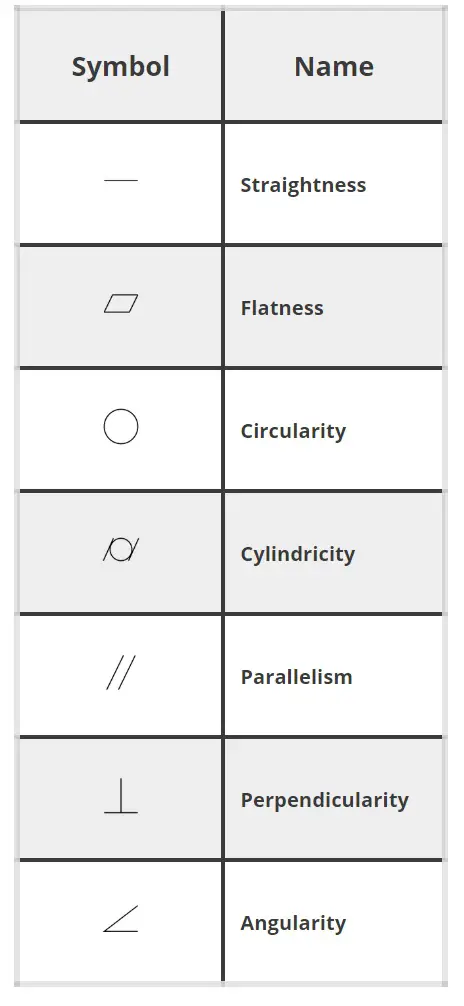
Symbol | Name | Description |
 | Straightness | Straightness is how close to a straight line a feature is. |
 | Flatness | Flatness is how flat a feature is. All points on the feature must lie within two parallel planes that are spaced the tolerance width apart. |
 | Circularity | Often called roundness. Circularity refers to how close to a perfect circle a single location is. Circularity is at one location. This can be thought of as a single circle on a cylinder. Usually circularity would be checked at multiple locations along the cylinder. This cylinder can be the inside of a hole, the outside of a shaft or various other features. |
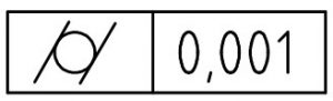
 | Cylindricity | Cylindricity is the same as circularity (often called roundness) with the exception that the requirement applies across the whole surface instead of at a single location. Cylindricity works to control taper whereas circularity does not. |
 | Parallelism | Parallelism refers to how close to 180 degrees two surfaces are. |
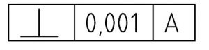
 | Perpendicularity | Perpendicularity is how close to 90 degrees two features are. This can be any combination of planes or axes. |
 | Angularity | Angularity is the same as perpendicularity with the exception that the two features are not at 90 degrees to one another but instead at a different specified angle. |
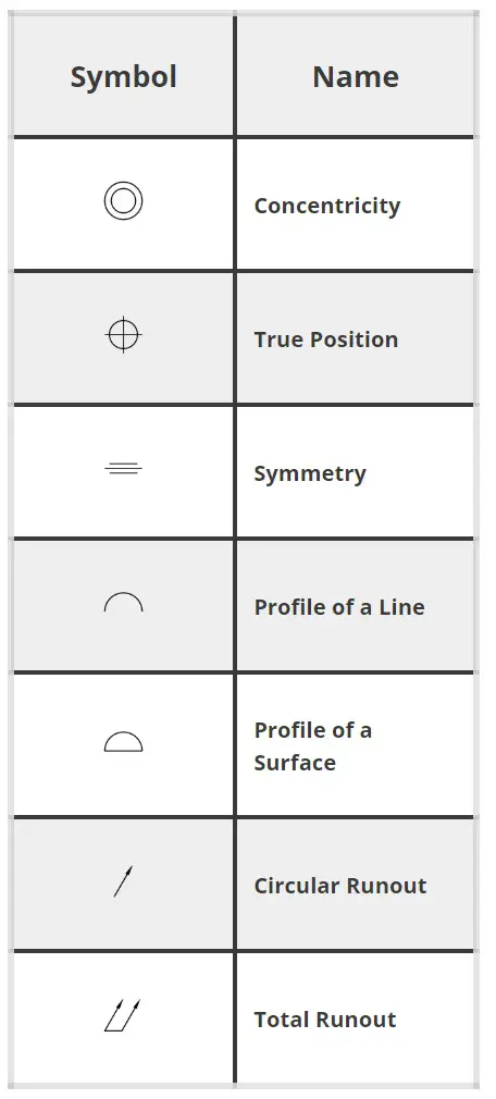
 | Concentricity | Concentricity is how close the axes of two features run together. |
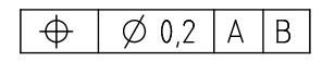
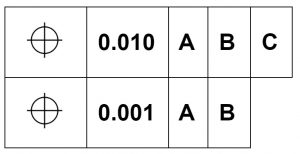
 | True Position | True position is a theoretically exact location of a feature. |
 | Symmetry | Symmetry is the same as concentricity but is applied to features that aren’t round. This means that the axes or centers of two features must run together. |
 | Profile of a Line | Profile of a line controls the shape of a cross section of a feature. It can control size, form and location. |
 | Profile of a Surface | Profile of a surface is similar to the profile of a line tolerance but it controls the entire surface instead of a single cross section. |
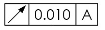
 | Circular Runout | Circular runout controls the runout in a single location of a circular feature such as a cylinder. |
 | Total Runout | Total runout controls the runout of an entire surface of a circular feature instead of at a single location. When compared to circular runout, total runout would check the entire cylinder. |
GD&T is a complicated subject and understanding it correctly can be the difference between a perfect part and scrap.
The best way to learn GD&T is from experienced teachers who can break down the material into manageable pieces.
Luckily, we know someone.
And MachinistGuides.com readers get an exclusive discount on training!
Get the Best GD&T Training AvailableFor more information see these related articles:
Symbol | Name | Description |
| | Straightness | Straightness is how close to a straight line a feature is. |
| | Flatness | Flatness is how flat a feature is. All points on the feature must lie within two parallel planes that are spaced the tolerance width apart. |
| | Circularity | Often called roundness. Circularity refers to how close to a perfect circle a single location is. Circularity is at one location. This can be thought of as a single circle on a cylinder. Usually circularity would be checked at multiple locations along the cylinder. This cylinder can be the inside of a hole, the outside of a shaft or various other features. |
| | Cylindricity | Cylindricity is the same as circularity (often called roundness) with the exception that the requirement applies across the whole surface instead of at a single location. Cylindricity works to control taper whereas circularity does not. |
| | Parallelism | Parallelism refers to how close to 180 degrees two surfaces are. |
| | Perpendicularity | Perpendicularity is how close to 90 degrees two features are. This can be any combination of planes or axes. |
| | Angularity | Angularity is the same as perpendicularity with the exception that the two features are not at 90 degrees to one another but instead at a different specified angle. |
| | Concentricity | Concentricity is how close the axes of two features run together. |
| | True Position | True position is a theoretically exact location of a feature. |
| | Symmetry | Symmetry is the same as concentricity but is applied to features that aren’t round. This means that the axes or centers of two features must run together. |
| | Profile of a Line | Profile of a line controls the shape of a cross section of a feature. It can control size, form and location. |
| | Profile of a Surface | Profile of a surface is similar to the profile of a line tolerance but it controls the entire surface instead of a single cross section. |
| | Circular Runout | Circular runout controls the runout in a single location of a circular feature such as a cylinder. |
| | Total Runout | Total runout controls the runout of an entire surface of a circular feature instead of at a single location. When compared to circular runout, total runout would check the entire cylinder. |
