Break Edge – All About

What is a break edge?
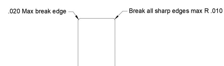
break edge blueprint examples

A break edge means the removal of material, usually in the form of a chamfer or radius to remove the sharp edge.

Machining a surface will often leave a corner which can be dangerous for both the part and the part handler. Many times there will be a burr (raised piece of material), left on the edge which can be razor sharp. Using a deburring tool can break the edge to remove the sharp 

A broken edge is usually specified as a maximum value or with no value at all. If no value is specified, the break edge has not been constrained sufficiently.

A break edge callout with no maximum size referenced would normally be assumed to be approximately .005-.010” though in some instances it could be larger.

What does a break edge look like?

Break edge on a physical part

In the brass cube below, notice how the corners have all the sharp edges removed. This is an example of a break edge.
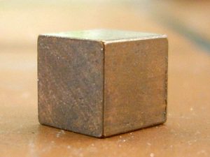
metal cube with break edge

Break edge on a blueprint

Break edge symbol

There is no GD&T symbol for a break edge. Break edges are also not referenced in the engineering drawing standard ASME Y14.5.

Break edge callouts are specified directly on the drawing to reference a certain surface or as a note e.g. “Break all sharp edges”.

At times, the break edge specification may be contained in the general tolerance block such as shown below.

Break edge note example

general break edge note on blueprint
Break edge note example

How to make a break edge

Break edge on wood

Using 180 grit fine sandpaper is the easiest way to create a break edge on a wooden workpiece. This can also be used together with a block plane to chamfer the edge and then soften it with a light sanding.

Break edge on metal

Because metal tends to be more durable, you have more choices for creating a break edge on your piece of metal.

You can use:

  • A chamfer deburring tool which is a specialty tool designed to remove burrs from the edges of parts
  • A file to knock the edge off a part
  • Sandpaper
  • A grinding wheel
  • A rotary tool such as a Dremel

Break edge on glass

To create a break edge on a piece of glass, use one of the following:

  • Diamond file
  • Grinding wheel
  • Rotary tool with diamond wheel

How to measure a break edge

Which measuring tools to use

igaging pocket comparator with reticles and case
A pocket comparator with various reticles for measuring

The size of a break edge is measured the same as a standard chamfer or radius. If a measurement is required, a pocket comparator or eye loupe with a reticle are the most common inspection tools to use. 

An optical comparator with or without an overlay could also be used. See the examples below to better understand how the size of a break edge would be determined.

How to measure the break edge based on your blueprint
break edge examples

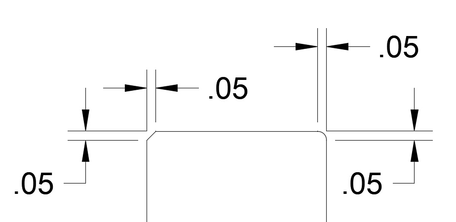
On the left is a chamfered break edge. The size is measured from the left edge of the part to the intersection of the break edge and the top of the part. This is done in both the x and y directions (up and down, left and right). 

On the right is a break edge created by a radius. The same measurement technique applies with the exception that the intersection would now be called the tangent point or point where the radius meets the straight edge.

Break edge compared to similar features

Break edge vs chamfer

The difference between a break edge dimension and a chamfer dimension is generally in the tolerancing of the two. A chamfer is usually thought of as being toleranced in a way that places tighter constraints on the feature. 

Often a chamfer callout will have a tolerance associated with the angle and a break edge will not.

Break edge vs radius

A break edge can be a radius. Many times, the person or company machining the part will round the edge using a variety of techniques including tumbling, specialty tools or even sandpaper.

Want to learn more?

GD&T is a complicated subject and understanding it correctly can be the difference between a perfect part and scrap.

The best way to learn GD&T is from experienced teachers who can break down the material into manageable pieces.

Luckily, we know someone.

And MachinistGuides.com readers get an exclusive discount on training!

Reference Dimensions [Guidance and Examples]

What is a reference dimension?

single reference dimension

A reference dimension is just what it sounds like. It is a dimension shown for reference. In other words it is there for informational purposes only.

They are not a requirement in any way.

Reference dimensions can be used to clarify other dimensions on a drawing. In some instances, they make a drawing easier to understand.

Reference dimensions on blueprints

How are reference dimensions shown on a drawing?

There is no GD&T symbol for a reference dimension. Reference dimensions are shown on a drawing as a value enclosed in parentheses.

An alternate method is to follow the dimension with “Reference” or “Ref”. The use of “Ref” or enclosing the dimension inside parentheses are by far the most common notations used. These notations are specified in ASME Y14.5 the Dimensioning and Tolerancing standard.

When to use a reference dimension

Reference dimensions are useful for clarification purposes. Their inclusion can make it clear how another dimension should be inspected or manufactured.

At other times they are included to make the drawing easier to read. It isn’t always immediately clear what a part looks like by looking at the blueprint.

A very common use of reference dimensions is to provide a conversion of the length units of the drawing from either metric to inches or vice versa.

Watch out for these conversions! Too often they are rounded excessively and not accurate. Reference dimensions should never be used for acceptance..

Reference dimension examples

reference dimensions

These examples show some of the variety you might see on your blueprints to call out reference dimensions.

Reference dimension measurement

Do reference dimensions have tolerances?

Reference dimensions do not have tolerances. Additionally, the general tolerances you find in a tolerance block do not apply to them.

Are reference dimensions measured?

Reference dimensions can be measured and the results recorded but this is not a requirement. Often reference dimensions will be recorded more as a note.

Reference dimension vs basic dimension

Reference Dimensions

Basic Dimensions

Shown in parentheses or with Ref notation

Shown enclosed in a box

Informational only

Controlled by another tolerance (GD&T)

Do not need to be measured or recorded

Will need to be measured for calculation

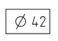
Basic dimensions are used in GD&T tolerancing. associated with another tolerance or dimension.

While they don’t have a tolerance tied to themselves, they are used to calculate the tolerance of another feature such as the true position of a hole. If the location of a hole was controlled by basic dimensions, you would never reject it for the hole location but instead for violating a GD&T requirement such as true position.

In other words, basic dimensions don’t have their own +/- tolerance but they are controlled by a different tolerance requirement.

single reference dimension
An example of a reference dimension
basic dimension example
An example of a basic dimension

Reference dimensions do not have a +/- tolerance and are not controlled by another requirement. They have no tolerance associated with them. No matter how far off the given value a reference dimension is, it would never be cause for rejection.

A basic dimension being far off its nominal value would not be cause for rejection itself, but its effect on another feature referencing the basic dimension could be cause for rejection.

Basic dimensions are identified with a rectangular frame around them such as in the example below.

Want to learn more?

GD&T is a complicated subject and understanding it correctly can be the difference between a perfect part and scrap.

The best way to learn GD&T is from experienced teachers who can break down the material into manageable pieces.

Luckily, we know someone.

And MachinistGuides.com readers get an exclusive discount on training!

Types of Tolerances Used On Blueprints [With Examples]

There are many different ways to specify tolerances on an engineering drawing. 

These tolerance types are shown below and include multiple examples for each tolerance type. 

Take note that the geometric tolerancing covers a wide variety of tolerancing applications. Follow the links in that section to go more in depth.

bilateral tolerance blueprint example
Bilateral tolerance example

Bilateral tolerances allow a plus or minus deviation from the nominal size.

In most instances, the plus/minus tolerances are equal but this is not a requirement.

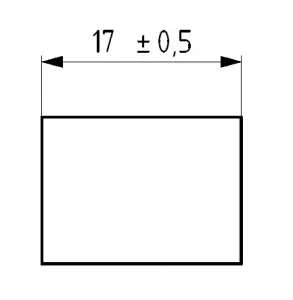
Bilateral tolerances can be uneven. For example, a tolerance of +0.1/-0.2 is a bilateral. +/- 0.1 is also bilateral.

Bilateral tolerance examples:

  • 10.5 +0.2/-0.2
  • 10.5 +0.2/-0.1
  • 10.5 +/- 0.5
unilateral tolerance blueprint example
Unilateral tolerance example

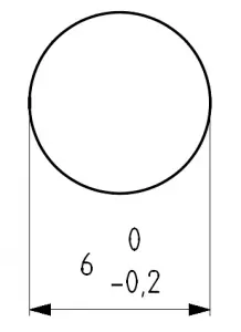
Unilateral tolerances allow variation in only one direction. This can be in either a positive or negative direction.

Some unilateral tolerance examples are:

  • 10.5 +0/-0.5
  • 10.5 -0.1/-0.5
  • 10.5 +0.4/+0
  • 10.5 +0.1/+1.1
limit tolerance example
Limit tolerance example

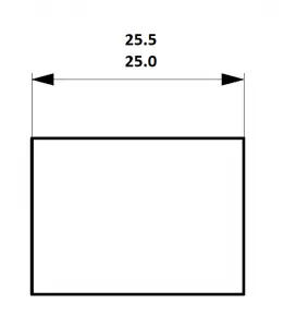
Limit tolerances directly specify the upper and lower limits of the tolerance. The feature size must fall within these limits.

Limit tolerance examples:

  • 10.5/10.7
  • 10.5-11.0
feature control frame description with parts identified
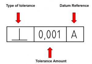
A feature control frame

GD&T Tolerancing

Geometric tolerancing with GD&T allows greater control over the the tolerances themselves. 

GD&T tolerances are able to control form, orientation, size and location. 

For more information on geometric tolerancing, see our posts on basic dimensions, datums, feature control frames, and blueprint symbols.

Want to learn more?

GD&T is a complicated subject and understanding it correctly can be the difference between a perfect part and scrap.

The best way to learn GD&T is from experienced teachers who can break down the material into manageable pieces.

Luckily, we know someone.

And MachinistGuides.com readers get an exclusive discount on training!

Chamfer and Chamfering Guide [Learn Quick]

What is a chamfer?

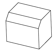
a picture of a chamfered part
A chamfered corner

A chamfer is an angle on the edge of a workpiece.

They are created for mainly for protecting the chamfered object as well as anyone who might come in contact with the object.

The edge can be the outside of the part, where a hole breaks through a surface or where any two surfaces meet. 

Notice the chamfered edges in the picture above.

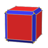
chamfered cube

The cube above has chamfered corners where all the main faces intersect.

Chamfering those intersections reduces the sharpness of, or softens the corners. 

Types of chamfers

Leg length chamfers

The most common way to spec a chamfer is by giving its leg length size and the chamfer angle.

In the picture of a triangle below, the legs are the a and b sides of the triangle.

right triangle with sides and angles identified

If no angle is given, the chamfer angle would be assumed to be 45 degrees. This can be a dangerous assumption though. It is always best to confirm the chamfer angle when not directly specified.

Face width chamfers

Occasionally, a chamfer will be specified as being measured as a face width. This can be seen abbreviated as F.W. on some blueprints. 

In the picture below, the leg length of the chamfer would be the length of the a and b sides. These would be equal in a 45 degree chamfer. The length of the c side would be the face width of the chamfer. 

right triangle with sides and angles identified

If a chamfer is called out as a face width, then it is to be measured along the hypotenuse of the chamfer. 

To convert a leg length dimension to face width simply multiply the leg length value by 1.414. To convert from a face width dimension to a leg length dimension, reverse the process and divide by 1.414. 

It should be noted that these conversion factors only work if the chamfer is at 45 degrees (the most common chamfer angle). If you need to calculate the face width of a chamfer at a different angle use a triangle calculator.

Chamfers compared to similar features

Chamfer vs bevel

A chamfer and a bevel are the same, especially in the case of machining.

Some will debate this point and argue that a chamfer takes the sharp corner off the part and that a bevel would do the same but all the way to the opposite side surface.

While there are some diagrams available online that will show this as true, this is incorrect. Merriam-Webster clearly defines a chamfer and bevel as the same thing.

Chamfer vs break edge

break edge blueprint examples
Break edge callouts

Chamfers are often left as an afterthought for blueprint drafters. 

Many times they have no functional requirement but are merely added to protect the part and anyone who might come into contact with it from damage. Deburring an edge is very similar.

In cases where the requirements are not strict, you will often see a break edge or break all edges requirement listed.

This means the sharp edge should be removed from part, but it is not directly controlled. In cases where a break edge is specified, the drafter is generally looking for a chamfer size of .010″-.020″ and sometimes even less.

Break edge callouts will rarely be identified with an angle associated with them.

Chamfer vs countersink

Countersink Blueprint GD&T Symbol two lines pointing down
Countersink blueprint symbol

Countersinks are chamfers applied to a round feature such as a hole. 

The main difference between chamfers and countersinks is that chamfers are usually specified at 45 degrees and countersinks have a larger variety of common angles.

Countersink angles are also specified as the angle between two opposite sides of the feature. This results in the angle spec being doubled. A 45 degree chamfer would often be listed as a 90 degree countersink. Common countersink angles are 82, 90, 100 and 120 degrees.

Chamfer vs deburr

As I noted above, a deburr callout is very similar to a break edge. Deburring is the act of removing a sharp edge and often raised edges along the feature. 

Tiny bits of raised metal can be quite dangerous. Deburring will remove these sharp bits. Similar to break edges, deburr callouts are usually pretty loosey goosey.

Chamfer vs fillet

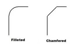
chamfer vs fillet comparison

A fillet is a rounded or radiused corner and a chamfer is a straight cut. Notice the difference in the picture above.

Chamfers do not have to be a 45 degree angle as shown in the picture above, but this is certainly the most common configuration.

How to specify chamfer dimensions

Dimensioning chamfers is done with a call out that specifies the length of the chamfer along with the angle of the chamfer. If no angle is given the chamfer is assumed to be at 45 degrees. 

Chamfers can also be specified by giving both legs of the chamfer such as:

Chamfer all edges .025″ x .025″

Chamfer notation example #1

chamfer callout blueprint note

If the example above read “Chamfer all edges and corners .030”, the callout would be the same as it is written currently.  Angles other than 45 degrees are used, but are much less frequent. 

Chamfers are often specified in the notes of a blueprint such as in the example above.

Chamfer notation example #2

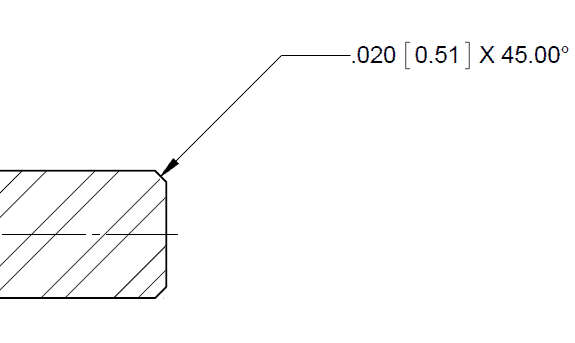
chamfer callout blueprint example

In this example, the chamfer would have a leg length of .020″ and a chamfer angle of 45.00 degrees.

Measuring chamfers

How to measure the size of a chamfer

igaging pocket comparator with reticles and case
Pocket comparator, otherwise known as an eye loupe

A chamfer length or depth can be measured utilizing many different pieces of measuring equipment. Optical comparators and CMMs are often used in industry, but if you are reading this you will likely want to measure your chamfer with a gauge called a pocket comparator, often referred to as an eye loupe. 

The pocket comparator uses a magnifying lens and reticle to enable the user to measure the size of the chamfer.

How to measure the angle of a chamfer

Chamfer angles are often assumed to be the same angle as the tool used to generate them. The most common chamfer angle is 45 degrees. 

Depending on the part geometry, different tools can be used to measure a chamfer’s angle. The angle can be calculated using the triangle calculator referenced above or a protractor can be used. 

Want to learn more?

GD&T is a complicated subject and understanding it correctly can be the difference between a perfect part and scrap.

The best way to learn GD&T is from experienced teachers who can break down the material into manageable pieces.

Luckily, we know someone.

And MachinistGuides.com readers get an exclusive discount on training!

Related Articles

Thru Hole – All About

What is a thru holes?

A thru hole, also known as a through hole, is a feature on a blueprint or drawing that identifies a hole to be machined with two open ends. The hole goes all the way through the part. In other words, the hole breaks through at two locations on the part.

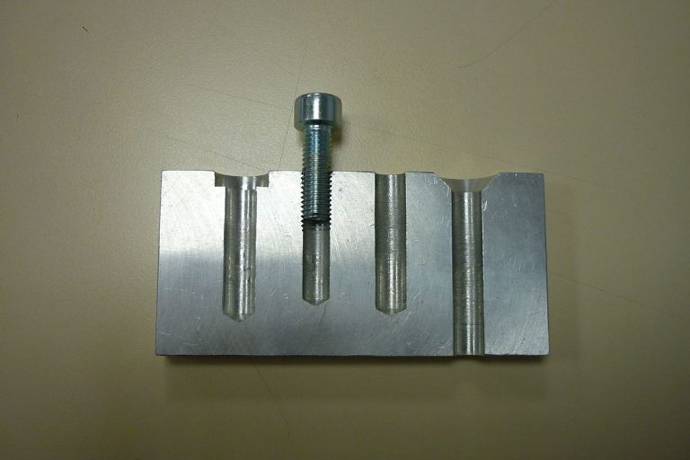
In the picture below, the thru hole is on the right. The other holes are blind holes.

cutaway example of blind and thru holes

How to dimension a thru hole?

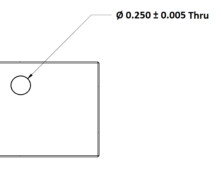
A thru hole is dimensioned by specifying the diameter of the hole along with a tolerance. Additional features can be added if needed such as a countersink or counterbore for the hole. No other features are required.

Thru hole vs blind hole

A thru hole has two open ends. A blind hole has one open end and does not go all the way through the part.

Thru hole symbol

There is no GD&T symbol for a thru hole though often it will be specified with the notation “THRU” on the engineering drawing.

Thru hole examples

thru hole blueprint example

Want to learn more?

GD&T is a complicated subject and understanding it correctly can be the difference between a perfect part and scrap.

The best way to learn GD&T is from experienced teachers who can break down the material into manageable pieces.

Luckily, we know someone.

And MachinistGuides.com readers get an exclusive discount on training!

Blind Holes – All About

What is a blind hole?

A blind hole is a hole that does not go all the way through a part. A blind hole goes to a specified depth and stops. 

How to dimension a blind hole

To specify a blind hole requires listing the diameter of the hole and a dimension to control the depth. The depth can be controlled by directly specifying the depth of the hole or by identifying the amount of material that will remain.

Blind hole vs thru hole

cutaway example of blind and thru holes

A thru hole, sometimes called a through hole, goes completely through a part. It has two open ends whereas a blind hole has one open end and does not break through to the opposite side. In the image above, the three holes on the left are all blind holes. The hole on the right is a thru hole.

Blind hole symbol

Diameter Blueprint GD&T Symbol o with line through it
Diameter symbol
Depth Blueprint GD&T Symbol line with arrow pointing down
Depth of symbol

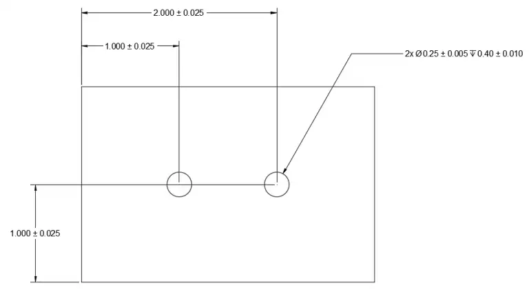
There is no GD&T symbol for a blind hole. A blind hole will be specified with a diameter and a depth specification or remaining amount of material. In the example below, the blind holes have a diameter of 0.25 and go to a depth of 0.40.

blind holes blueprint example

Can you make a flat-bottomed blind hole?

You can make a flat bottom blind hole, but it can be difficult depending upon what type of material is being drilled. A modified drill bit or an end mill can work.  This video explains some tips.

Blind hole example

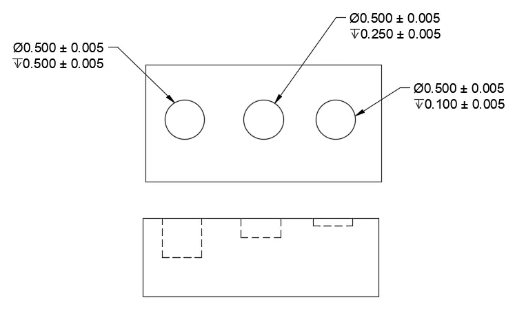
The example below has three blind holes. They all have a diameter of 0.500 but they have different depths. From left to right, the depths are 0.500, 0.250 and 0.100.

blind holes blueprint example

Want to learn more?

GD&T is a complicated subject and understanding it correctly can be the difference between a perfect part and scrap.

The best way to learn GD&T is from experienced teachers who can break down the material into manageable pieces.

Luckily, we know someone.

And MachinistGuides.com readers get an exclusive discount on training!

Limit Tolerances – All About

What is a limit tolerance?

limit tolerance example

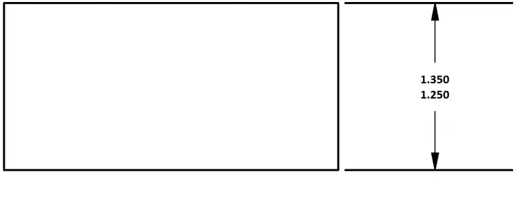
A limit tolerance is a form of dimensional tolerancing that specifies a tolerance range for a specific feature. Limit tolerances are also known as limit dimensioning and are an effective way to specify requirements on a blueprint. They clearly identify the tolerance range without requiring additional calculations by the blueprint reader.

Limit tolerance symbol

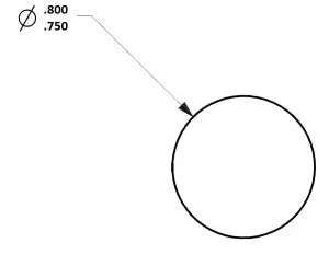
There is no GD&T symbol for a limit tolerance. Per ASME Y14.5, the notation for a limit tolerance is to callout the upper and lower tolerance boundaries for a dimension. The upper end value of the tolerance range goes on top of the lower end value as shown in the examples below.

Limit tolerance examples

limit tolerance example

Limit tolerance vs unilateral tolerance

unilateral tolerance blueprint example
Unilateral tolerance example

A unilateral tolerance lists a nominal value along with a plus or minus tolerance. Using these two values allows the blueprint reader to calculate the upper and lower ends of the tolerance range. A limit tolerance skips the calculation step and directly specifies the upper and lower end of the tolerance range. If the unilateral tolerance above was instead specified as a limit tolerance it would be 5.8-6.0.

Limit tolerance vs bilateral tolerance

bilateral tolerance blueprint example
Bilateral tolerance example

A bilateral tolerance lists a nominal value along with a plus/minus tolerance. Using these two values allows the blueprint reader to calculate the upper and lower ends of the tolerance range. A limit tolerance skips the calculation step and directly specifies the upper and lower end of the tolerance range. If the bilateral tolerance above were instead specified as a limit tolerance it would be 16.5-17.5.

Want to learn more?

GD&T is a complicated subject and understanding it correctly can be the difference between a perfect part and scrap.

The best way to learn GD&T is from experienced teachers who can break down the material into manageable pieces.

Luckily, we know someone.

And MachinistGuides.com readers get an exclusive discount on training!

Spotfaces – All About

What is a spotface?

spotface example on part

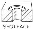
A spotface is a machined section of a part that allows a fastener to sit flat. This is usually a bolt head or washer but can be other fasteners. A spotface is generally very shallow and removes just enough material to create the clean, even, flat surface. Spotfaces are most often used when machining castings or forgings. Spotfacing is done using a manual or CNC milling machines.

Spotface vs counterbore

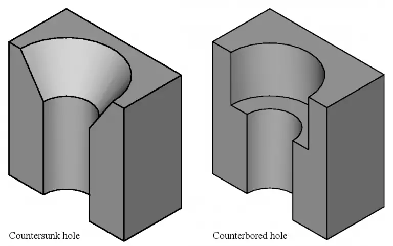
A spotface is functionally no different than a counterbore. A counterbore usually references a feature that is deeper than a spotface. While a spotface creates a flat mounting surface, a counterbore acts to recess the fastener. It would be safe to call a spotface a counterbore but not the other way around.

cutaway examples of countersink and counterbore

Spotface vs countersink

The primary difference between a countersink and a spotface is that the countersink has an angled bottom whereas a spotface has a flat bottom.

Spotface symbol

Spotface Blueprint GD&T Symbol SF in a u
Spotface symbol
Counterbore Blueprint GD&T Symbol u shape
Counterbore symbol

The symbol used to callout a spotface is the counterbore symbol with the letters SF in the middle. This is per the engineering drawing standard ASME Y14.5. At times, a blueprint may indicate a spotface feature simply through the use of a counterbore symbol. Additionally, older drawings and blueprints may reference a spotface as SF or SFACE instead of using the symbol.

How to dimension a spotface

spotface blueprint example

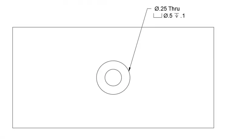
A spotface is dimensioned by specifying its diameter and depth. At times the amount of remaining material may be specified instead of the depth. The symbols for diameter and depth are shown below.

Diameter Blueprint GD&T Symbol o with line through it
Diameter symbol
Depth Blueprint GD&T Symbol line with arrow pointing down
Depth symbol

Spotface example

spotface cutaway example

Want to learn more?

GD&T is a complicated subject and understanding it correctly can be the difference between a perfect part and scrap.

The best way to learn GD&T is from experienced teachers who can break down the material into manageable pieces.

Luckily, we know someone.

And MachinistGuides.com readers get an exclusive discount on training!

Countersinks – All About

What is a countersink?

A countersink is an angled taper applied to a hole that allows a fastener (usually a flat head screw or similar) to sit even with, or below the surface which has been countersunk. Occasionally, a countersink is used simply as a method of chamfering or deburring a hole.

Countersink symbol

Countersink Blueprint GD&T Symbol two lines pointing down

The GD&T callout for a countersink is shown below. Some older blueprints may use the notation CSK to identify a countersink dimension.

If you want to type the ⌵ symbol, hold the ALT key and press 9013. See this list for other common keyboard shortcuts for GD&T and blueprint symbols.

How to dimension a countersink

countersink blueprint example

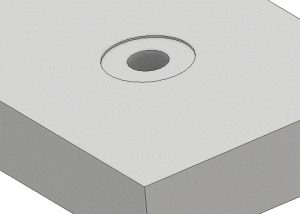
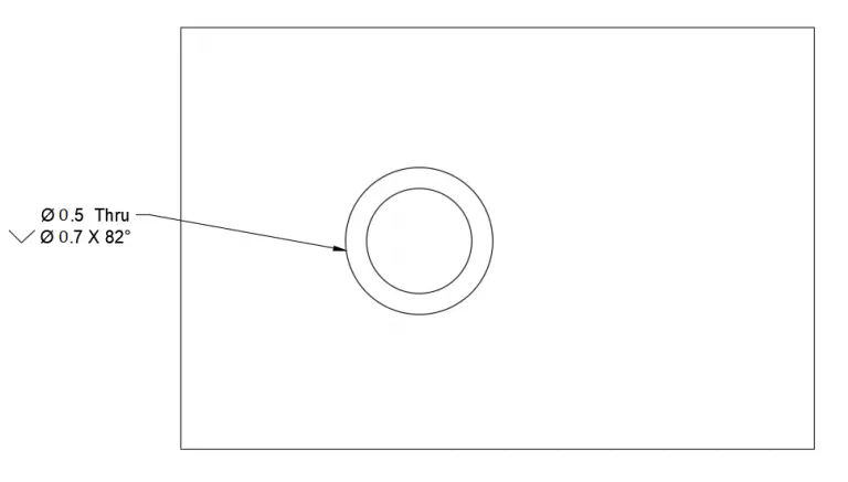
A countersink is dimensioned by specifying the diameter of the countersink where it meets the surface and the included angle. In the above example, the part has a 0.5 thru hole and a countersink with a diameter of 0.7 and an included angle of 82°.

How to measure a countersink

Countersinks can be measured by many different gauges. The easiest tool to use, assuming the tolerances aren’t too tight, is a pocket comparator with a reticle. Optical comparators and CMMs are regularly used to measure countersinks with very tight tolerances.

What does a countersink look like?

countersink example on part

Countersink vs chamfer

A countersink and a chamfer are very similar. A countersink is basically no different than a chamfer on a hole.

The main difference is that a chamfer is normally thought of as being at 45 degrees (though the angle can vary). A countersink is usually one of many different standard angle sizes.

The most common countersink angles are 82°, 90° or 100°.

Note that in the case of the 90° countersink, this callout is the same as a 45° chamfer because the countersink angle takes both sides into account, so it is twice the chamfer angle.

Countersink vs counterbore

cutaway examples of countersink and counterbore

The difference between a countersink and a counterbore is that a countersink has an angled bottom and a counterbore has a flat bottom. Countersinks are often used to recess a flat head screw. Counterbores are used to recess bolts, washers and other fasteners.

Countersink vs spotface

spotface example on part
Spotface example

A spotface has a flat bottom like a counterbore while a countersink is angled. A spotface is used to create a flat area in a specific location to allow a fastener such as a screw or bolt to sit squarely.

Want to learn more?

GD&T is a complicated subject and understanding it correctly can be the difference between a perfect part and scrap.

The best way to learn GD&T is from experienced teachers who can break down the material into manageable pieces.

Luckily, we know someone.

And MachinistGuides.com readers get an exclusive discount on training!