There are many different ways to specify tolerances on an engineering drawing.
These tolerance types are shown below and include multiple examples for each tolerance type.
Take note that the geometric tolerancing covers a wide variety of tolerancing applications. Follow the links in that section to go more in depth.
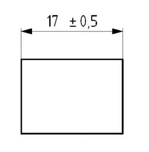
Bilateral tolerances allow a plus or minus deviation from the nominal size.
In most instances, the plus/minus tolerances are equal but this is not a requirement.
Bilateral tolerances can be uneven. For example, a tolerance of +0.1/-0.2 is a bilateral. +/- 0.1 is also bilateral.
Bilateral tolerance examples:
- 10.5 +0.2/-0.2
- 10.5 +0.2/-0.1
- 10.5 +/- 0.5
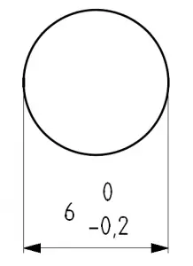
Unilateral tolerances allow variation in only one direction. This can be in either a positive or negative direction.
Some unilateral tolerance examples are:
- 10.5 +0/-0.5
- 10.5 -0.1/-0.5
- 10.5 +0.4/+0
- 10.5 +0.1/+1.1
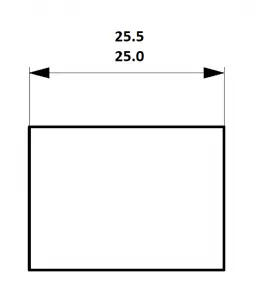
Limit tolerances directly specify the upper and lower limits of the tolerance. The feature size must fall within these limits.
Limit tolerance examples:
- 10.5/10.7
- 10.5-11.0

GD&T Tolerancing
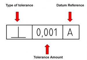
Geometric tolerancing with GD&T allows greater control over the the tolerances themselves.
GD&T tolerances are able to control form, orientation, size and location.
For more information on geometric tolerancing, see our posts on basic dimensions, datums, feature control frames, and blueprint symbols.
Want to learn more?
GD&T is a complicated subject and understanding it correctly can be the difference between a perfect part and scrap.
The best way to learn GD&T is from experienced teachers who can break down the material into manageable pieces.
Luckily, we know someone.
And MachinistGuides.com readers get an exclusive discount on training!


